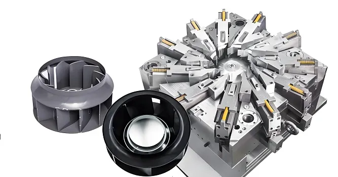
Precision Micro Injection Molding Services for Miniature Plastic Parts
Micro injection molding for miniature plastic parts and micro-scale features — where shot control, micro tooling design and per-feature dimensional verification decide the outcome, batch after batch.
This page explains what actually determines micro molding quality: how fill is controlled at small shot volumes, how micro tools are designed for balance and ejection, and how critical tolerances are verified. Send your drawing for DFM review before committing to tooling.
The RFQ checklist on this page is shown in full. Select the text to reuse it, or use your browser's print / save-as-PDF — Goldcattle does not host downloadable files on this site.
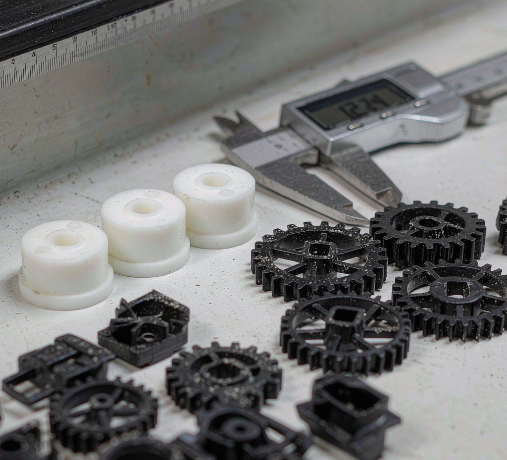
What Is Micro Molding — and How It Differs from Small-Part Molding
Micro injection molding is molding where the part scale — feature size, tolerance or shot volume — drives the process. It is not defined by press size or a part weight threshold; it is defined by how much engineering attention fill, gating, venting, ejection and measurement each require.
In practice, a part crosses into micro-molding territory when its features are small enough that a standard small-part tool and process window start producing variation: cavity-to-cavity imbalance, flash on micro features, short shots in thin flow paths, and measurement errors that are as large as the tolerance itself. The distinction matters commercially, because a part quoted and tooled as an ordinary small part can hit these problems only after steel is cut.
Micro injection molding
Tooling, process window and measurement are engineered around the micro scale: gate and runner design, venting, ejection of tiny parts, per-cavity balance verification, and dimensional inspection against the drawing datum. Critical tolerances are confirmed per feature at mold validation.
Conventional small-part molding
Standard tooling and process practice, efficient when feature sizes and tolerances sit within normal molded-part practice. The part scale does not drive the tool design, and a single validated cavity often represents the whole tool.
Adjacent processes
Micro CNC and micro 3D printing cover needs injection molding does not — metal micro parts, or no tooling at all. They are compared against micro molding in the process selection section below.
The engineering question to ask any supplier
Not "do you have micro machines" — but "how do you verify that every cavity fills the same way, and how do you measure a feature whose tolerance is close to your measurement error?" A supplier's answers on fill balance, venting, ejection and measurement method tell you whether the part will be consistent in production.
Shot Control and Material Flow at Micro Scale
At micro scale the shot is small enough that material temperature, fill speed and cavity balance dominate the result. Four process factors decide whether every cavity fills the same way, every shot.
| Process factor | Why it decides the outcome | How it is controlled |
|---|---|---|
| Shot volume control | In a small shot, a metering error that would be invisible in a large part becomes a measurable part-to-part difference. | Dosage consistency and screw recovery are verified per material during process development, and the validated window is documented. |
| Fill balance across cavities | Micro runners amplify imbalance: one cavity fills early while another is still short, and the difference shows up as dimensional scatter. | Cavity-to-cavity fill is measured at trial — short-shot studies and part weighting — and runner or gate geometry is corrected in the tool. |
| Shear heating and melt temperature | Small gates and high fill speed generate shear heat that can degrade the resin, changing flow and mechanical properties shot to shot. | The process window is set with measured melt temperature rather than assumed, and fill velocity is profiled against the resin's limits. |
| Venting and trapped air | Micro cavities vent poorly; trapped air compresses at the end of fill and causes burn marks or incomplete fill. | Vent channels are engineered into the tool, and fill profiling — or vacuum venting where required — keeps air ahead of the flow front. |
What this means in a quotation: the process window — melt temperature, fill speed, pack and hold profile — is documented and verified at mold validation, so production repeats the validated window instead of drifting with operator or shift changes.
Micro Mold Design: Six Factors That Decide the Outcome
Six mold design factors decide whether a micro tool produces consistent parts. Each is reviewed at DFM — before steel is cut, not after the first parts fail.
- Gate and runner design at micro scale: gate size and location set the fill pattern, shear level and vestige; the micro runner layout drives cavity balance and is corrected at trial, not in production.
- Parting line and flash control: at micro feature sizes, even thin flash is a defect; parting surface design and steel condition are specified to control flash at the parting line and gate.
- Ejection of micro parts: tiny parts stick, scatter and double-load; pin placement, air assist and part handling are designed into the tool rather than improvised on the machine.
- Venting: trapped air in micro cavities burns or short-fills the part; vent channels and, where required, vacuum venting are engineered in.
- Cavity finish and texture: micro surface finish affects flow and part release; finish is specified per functional surface — sealing, optical contact or assembly.
- Multi-cavity balance: cavity-to-cavity variation dominates small-part tolerance; balance is measured at trial, and family tools are reviewed for balance risk before quoting.
Materials for Micro Molding
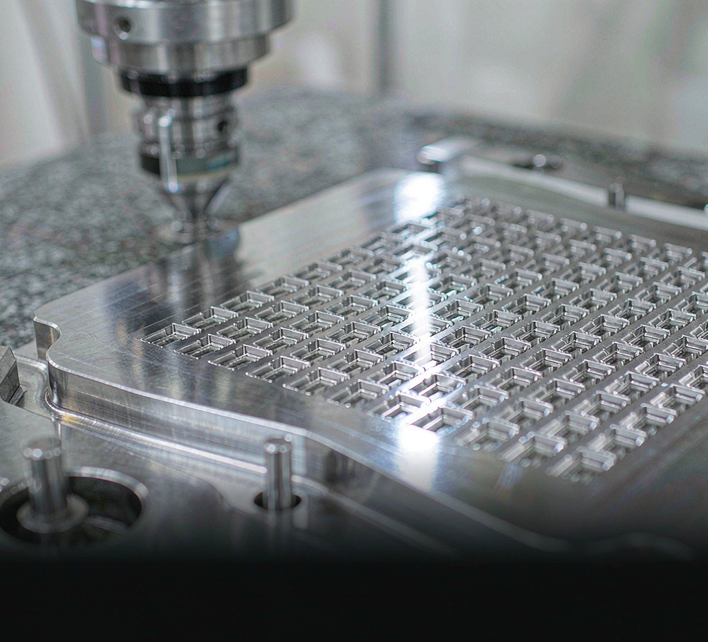
Three material families cover most micro molding projects. Grade selection considers flow at micro scale, filler abrasion on the tool, service temperature and traceability needs — it is a project decision, confirmed at DFM.
| Family | Typical grades | Micro-molding considerations |
|---|---|---|
| Unfilled commodity resins | PP, PE, ABS, PC, PS. | Flow readily through small features with lower shrink variation; a common choice for connectors, housings and micro mechanical parts. |
| Engineering resins with fillers | PA6, PA66, POM, PBT, PPS — glass- or mineral-filled. | Higher strength and service temperature, but filler content changes micro-scale flow and increases tool wear; wear and balance are verified at trial. |
| High-performance resins | PEEK, PEI, LCP, PPSU. | High service temperature and chemical resistance; tighter process control and material traceability; medical-contact and regulated grades are reviewed per project. |
Standard materials and available grades are defined separately in our material documentation, and grade availability is confirmed at quotation. Resin certificates are tied to the production batch, so a shipped part can be traced back to its material lot.
Inspection and Verification Matrix
Micro parts fail on variation, not only on single dimensions. Six checks cover what actually moves: dimensional accuracy, cavity-to-cavity balance, flash, surface, fit and documentation.
| Check | Question it answers | Recommended method |
|---|---|---|
| Dimensional measurement | Are critical features within the drawing's permitted deviation? | Optical measurement systems and CMM for accessible features, measured against the drawing datum. |
| Cavity-to-cavity balance | Do parts from different cavities measure the same? | Measure across cavities — not a single "golden" part — and compare against the permitted deviation. |
| Flash and burr | Is there flash at the parting line or gate vestige outside limits? | Visual inspection against a defined acceptance standard agreed with you before production. |
| Surface finish | Does the functional surface meet its roughness or appearance requirement? | Roughness measurement or comparator where the function requires it. |
| Assembly and functional fit | Does the part fit and function in the assembly? | Fit checks with mating parts or gauges where available; functional test definition agreed at quotation. |
| Documentation | Can a shipped part be traced back? | First-article inspection reports, resin lot, cavity ID and process records tied to the batch. |
Common Defects in Micro Molding and How They Are Prevented
Six defects account for most micro molding problems. Each has a root cause in fill, tooling or measurement — and a prevention that belongs in the tool design, not in rework after the run.
| Defect | Typical cause at micro scale | Prevention |
|---|---|---|
| Short shot | Micro runners freeze before fill completes; the shot or temperature window is too narrow. | Fill balance study, gate and runner sizing, and a verified process window documented at validation. |
| Flash | Thin parting surfaces and micro features trap material at the parting line. | Parting line land design, steel condition and balance, and a validated clamp setting for the tool. |
| Burn marks | Trapped air in micro cavities compresses at the end of fill and scorches residue. | Vent design, fill profiling and, where required, vacuum venting engineered into the tool. |
| Jetting | High-velocity flow through small gates snakes into the cavity instead of filling front to back. | Gate location and type selection, velocity profiling and sequential fill where applicable. |
| Sink marks | Thick micro sections cool from the outside while the core is still soft. | Wall uniformity and core-out at DFM, with pack and hold profile verified at trial. |
| Dimensional drift | Cavity-to-cavity imbalance and slow process drift across the run. | Balance measurement at trial, a documented process window and in-process checks in production. |
Where Micro Molding Is Used
Micro molding serves any product whose function sits in small plastic features. Project fit is confirmed at DFM — the applications below show where the process is commonly used, not a claim about your specific part.
Medical device components
Non-implant plastic components where documentation, traceability and process control matter. The applicable documentation set and controls are confirmed per project during review.
Electronic connectors
Micro-pitch terminals, housings and insulating components where insert — or feature — position accuracy and flash control are critical.
Micro gears and drives
Micro gears, cams and drive components where cavity-to-cavity consistency matters more than any single part's dimensions.
Sensor and instrument housings
Small housings and structural components for sensors and instruments, often with tight fit or sealing requirements at the mating interface.
Automotive micro components
Clips, sensor components and micro mechanical parts where production volume rewards a validated, balanced tool.
Consumer and industrial device parts
Small functional components in appliances, tools and equipment — typically where assembly automation needs consistent part-to-part behavior.
What we confirm, what we review per project, and what we do not claim
Confirmed: in-house mold making under our ISO 9001:2015 quality system, process windows documented at mold validation, and batch traceability from resin lot to shipped part.
Reviewed per project: critical tolerances, material grade, measurement method and the documentation set for regulated industries — for medical-device components we describe process controls as ISO 13485-aligned and confirm the applicable documentation with you; this is a description of practice, not a certification claim.
Not claimed: dedicated micro press models or clamp force, minimum shot weight or part mass, cleanroom class, or any blanket tolerance such as a single ± figure. Dimensional capability is application-dependent. Critical tolerances are reviewed against the resin grade, feature geometry, tooling strategy and measurement method before production approval.
Cost and Process Selection for Miniature Parts
Process choice is a cost-and-feasibility question: tooling investment, per-part cost at your volume, material range and the feature scale your part needs. Four routes cover most miniature part programs.
| Route | Tooling | Best fit | Trade-offs |
|---|---|---|---|
| Micro injection molding | Injection tool required | Production volumes with a stable design | Lowest per-part cost at volume once the tool is amortized; tooling investment and lead time sit up front. |
| Conventional small-part injection molding | Injection tool required | Parts whose scale does not drive the tool design | Efficient standard tooling; may not control micro features, cavity balance or measurement error. |
| Micro 3D printing | No tooling | Prototypes, bridge volume, design iteration | Per-part cost stays high; resin range, surface and dimensional characteristics differ from molded parts. |
| Micro CNC machining | Programming and setup, no injection tool | Metal micro parts and very low volumes | Subtractive limits on internal micro features; per-part cost is driven by setup rather than run rate. |
The decision rule: if volume is stable and the design is frozen, micro molding usually wins on per-part cost once the tool is amortized. If volume is low or the design is still moving, 3D printing or micro CNC is the lower-risk start. We will say which route we believe fits — even when it is not the higher-value one for us.
What to Send With Your Micro Molding RFQ
A complete RFQ gets an accurate quotation faster. Nine items cover what engineering needs to assess tooling, process and verification for a micro part.
| Item | What to include |
|---|---|
| Drawings | 3D CAD and 2D drawings at a named revision (STEP, IGES, STL, DWG, DXF or PDF). |
| Critical tolerances | Which features are critical, with target and limit values — these drive tooling strategy and measurement method. |
| Material | Resin grade, color and filler content, or the requirement the material must meet. |
| Volume | Annual quantity, program life and batch plan. |
| Application and environment | What the part does, service temperature and any chemical exposure. |
| Inspection requirements | Report type, sampling plan, and any gauges or fixtures you can provide. |
| Assembly context | Mating parts, fit requirements and any functional test the part must pass. |
| Timeline | Target dates for samples, validation and production start. |
| Commercial details | Destination, Incoterms, packaging and labeling requirements. |
Frequently Asked Questions
What is micro injection molding?
Micro injection molding produces miniature plastic parts and micro-scale features under tighter process control than conventional small-part molding: shot volume, fill balance, gating, venting, ejection and measurement are each engineered for the part's scale. There is no single industry threshold — what separates micro molding is that the process and tooling are designed around very small features and very small shot volumes, not the size of the press.
How small can micro molded parts be?
Feasibility depends on the resin grade, feature geometry, tooling strategy and measurement method, so we do not publish a single minimum part size or shot weight. Minimum part and feature sizes are confirmed with your drawing during DFM review.
What tolerances can micro injection molding hold?
Dimensional capability is application-dependent. Critical tolerances are reviewed against the resin grade, feature geometry, tooling strategy and measurement method before production approval. Molded tolerance is confirmed per critical feature at mold validation — it is not quoted as one blanket number.
What plastics can be micro molded?
Three material families cover most projects: unfilled commodity resins such as PP, PE, ABS and PC; engineering resins with fillers such as PA, POM, PBT and PPS; and high-performance resins such as PEEK, PEI and LCP. Grade selection considers flow at micro scale, filler abrasion on the tool, service temperature and any material traceability requirements.
How does micro molding compare with 3D printing and micro CNC machining?
3D printing needs no tooling and suits prototypes and bridge volumes; micro CNC machines metal micro parts and suits very low volumes; conventional injection molding suits parts whose scale does not drive the tool design. At production volume with a stable design, micro molding usually carries the lowest per-part cost once the tooling is amortized.
What do you need to quote a micro molding project?
3D CAD and 2D drawings at a named revision, critical tolerances, resin or material requirement, estimated annual volume, application and service environment, inspection requirements, assembly context and target timeline.
Planning a miniature plastic part?
Send the drawing, critical tolerances and material requirement. Our engineering team reviews fill, tooling strategy and measurement method with you, confirms what is verifiable before production approval, and quotes tooling and production with the schedule staged by gate.
- DFM review of critical tolerances and tooling strategy before commitment
- Documented process window verified at mold validation
- Per-cavity dimensional verification and batch traceability

Reviewed this page on 2026-10-19. Process and tooling practices follow general micro-molding engineering principles; tolerances, materials and capability for your part are confirmed per project at DFM review and mold validation. Technical and commercial questions are answered within 24 hours.