Process guide · metal and ceramic powder
Powder Injection Molding: MIM, CIM and the Route That Fits Your Part
Powder injection molding is not plastic injection molding with metal in it. It is a family of processes in which powder and binder are moulded into a shape that is deliberately too large, emptied of its binder, and then sintered until it shrinks to the drawing. Almost everything that goes wrong happens after the mould — which is why the debinding and sintering stages, not the moulding stage, decide whether the part is right.
Scope of this page, and of our capability
This page explains the PIM family and how to choose a route through it. It deliberately does not restate equipment counts, capacity, density or tolerance figures for MIM and CIM — those statements live on the capability pages themselves, and a figure repeated on two pages is a figure that will eventually disagree with itself.
Our published capability statements are on metal injection molding capabilities and custom ceramic injection molding. If your project turns on a specific number from either page, ask about it against your part and it will be answered in writing.
PIM is also not a synonym for plastic injection moulding, and it is not powder compaction: the powder is carried into the shape as a melt and densified afterwards by sintering, which is a different economics and a different set of failure modes.
At a Glance
One Process Chain, Two Material Families
Short answer: PIM is the umbrella. MIM and CIM are not two brands of the same thing — they are the same six steps run on two material systems that behave differently at every stage after moulding.
Confusing them is the most common error in PIM content, and it matters commercially: a supplier who can sinter stainless steel in hydrogen may have no route for a zirconia part, and the debinding window that suits one feedstock will crack the other. The table below is the distinction that actually changes a quotation.
| MIM — metal | CIM — ceramic | |
|---|---|---|
| Powder | Metal powder, often a pre-alloyed grade to hold composition through sintering | Ceramic powder, frequently with sintering aids to control densification and grain growth |
| What the finished part is for | Strength, ductility, corrosion resistance, conductivity, heat-treatability | Hardness, wear resistance, electrical insulation, chemical and thermal stability |
| Debinding | Binder system chosen to leave no carbon or oxygen that would spoil the alloy | Binder removal has to avoid reducing or contaminating the ceramic; residual carbon changes colour and properties |
| Sintering | Controlled atmosphere matched to the alloy — a stainless part and a titanium part cannot share a cycle | Higher temperatures, tight atmosphere and firing schedule control; grain growth is a property risk |
| After sintering | Sizing, machining, heat treatment, passivation, plating | Diamond grinding and polishing, often the only practical finishing route |
| Failure that hurts most | Porosity or composition drift that shows up as a mechanical or corrosion failure | Brittle fracture from a flaw, or a dimensional shift that cannot be ground back |
| Typical rejection risk | Cracks and distortion in debinding and sintering; density shortfall | Internal flaws and edge chipping; warpage that cannot be corrected after firing |
If a quotation treats “PIM” as one capability, ask which of the two it is quoting and what furnace atmosphere is used for your alloy. The answer is usually decisive.
The Six Stages, and What Each One Can Ruin
Short answer: the mould only sets the shape. Debinding and sintering set the size, the density and the properties — and that is where most PIM problems are created.
Feedstock
Powder and binder compounded into a homogeneous, injection-mouldable granulate. Powder size distribution and binder ratio set shrinkage and defect risk.
Moulding
Injected into a tool cut oversize. Gate, weld lines and shear are the concerns, exactly as in plastic moulding — but any flaw here is inherited by every later stage.
Green part
Binder holds the powder together. Weak, and easily damaged in handling. Green strength limits how thin and how unsupported the geometry can be.
Debinding
Binder removed by solvent, thermal or catalytic route. Too fast and the part blisters, cracks or slumps; too slow and the cycle cost rises.
Sintering
Brown part densified in a controlled atmosphere. This is where the part shrinks to size, gains strength and loses the last of its porosity.
Finishing
Sizing, machining, heat treatment, grinding, coating. Anything the as-sintered tolerance cannot hold is recovered here — at a cost.
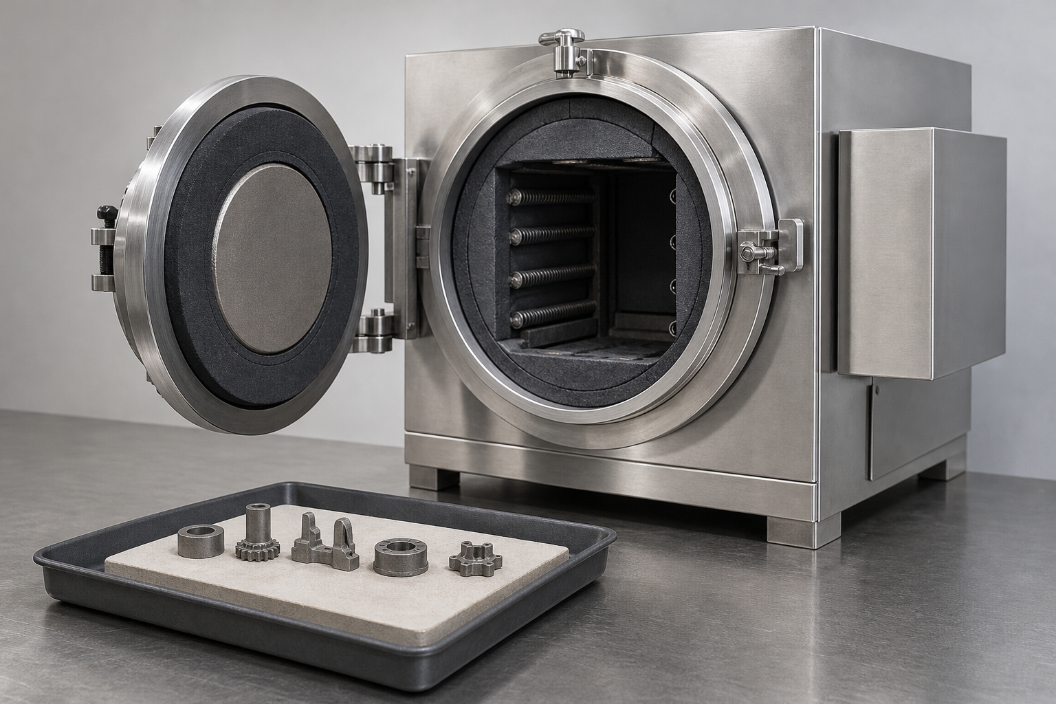
The practical consequence for a buyer: a PIM quotation is mostly a quotation for stages 1, 4 and 5, not for moulding. When two suppliers quote very differently on the same part, the difference is usually the furnace route and the number of trial cycles they have allowed for.
MIM or CIM: Choosing the Material Route
Short answer: the material requirement decides the route before cost is discussed. If the part must conduct, deform rather than shatter, take a thread or be heat treated, the answer is MIM. If it must insulate, resist wear at temperature, or survive a chemical environment where metals fail, the answer is CIM.
Choose MIM when the part is metal
- Complex geometry that would otherwise be several machining operations
- An alloy that is expensive as bar stock or unpleasant to machine, such as a stainless or a tool steel
- A part small enough that the tool cost is recovered by the per-part saving
- Need for ductility, conductivity, weldability or a heat-treatment response
- Volume sustained enough to justify the tool and the sinter development
Choose CIM when the part is ceramic
- Electrical insulation, or a dielectric behaviour no metal provides
- Wear resistance at temperature, or chemical inertness
- Complex near-net shape in a material that cannot be machined economically after firing
- A tolerance that can be met as-sintered or by diamond grinding
- A design that tolerates brittleness — no impact loading, no bending stress concentration
Neither route is a substitute for the other, and neither is a substitute for machining at low volume. Where the requirement is “a metal part” without a specific reason to mould it, the honest comparison is against CNC machining — not against CIM.
Design for PIM: Rules That Come From Sintering, Not Moulding
Short answer: a PIM part has to survive being handled as a weak green body and then being heated until it shrinks. Design rules that only consider cavity filling are half the rules.
| Design point | Why it matters in PIM specifically | What to do about it |
|---|---|---|
| Uniform wall thickness | Thick and thin regions densify and shrink at different rates, so the part distorts rather than simply scaling down | Keep sections as even as the function allows; where thickness must change, transition gradually rather than stepping |
| Rounded edges and corners | Sharp internal corners concentrate stress and are where cracks start during debinding and sintering | Radius the corners; treat sharp internal geometry as a defect risk rather than a machining convenience |
| Local mass accumulation | A heavy boss or a thick hub cools, debinds and sinters differently from the wall around it | Core it, pocket it, or accept that it will need support and may still distort |
| Long spans and cantilevers | The brown part is weak and unsupported spans sag under their own weight at sintering temperature | Design supports or sintering fixtures in from the start; a long thin cantilever may not be achievable net-shape |
| Holes, threads and undercuts | Small cores are fragile in the green body; fine threads rarely survive sintering to tolerance | Mould what can be moulded, and plan to drill, tap or machine the rest after sintering |
| Critical tolerances | As-sintered tolerance is a property of alloy, size and furnace, not a process constant | Mark which dimensions must be net-shape and which may be sized, ground or machined; the split drives the price |
| Datum scheme | If the datum is itself a sintered surface, measurement uncertainty is built into every other dimension | Nominate a stable datum, often a machined face, and say so on the drawing |
Debinding, Sintering and Dimensional Control
Short answer: the tool is cut oversize on purpose. The part is moulded at a size that will shrink to the drawing once the binder is gone and the powder has densified — and the amount it shrinks is a property of that feedstock and that furnace cycle, measured on trials rather than assumed.
The reason the shrinkage is large compared with thermoplastic moulding is structural, not a matter of degree. In a thermoplastic part, the material is the part and cooling shrinkage is a fraction of a percent to a couple of percent. In a PIM part, the green body is mostly powder by volume with binder filling the gaps; the binder leaves, and then the powder particles bond and pull together, closing the space between them. The part does not simply cool — it densifies.
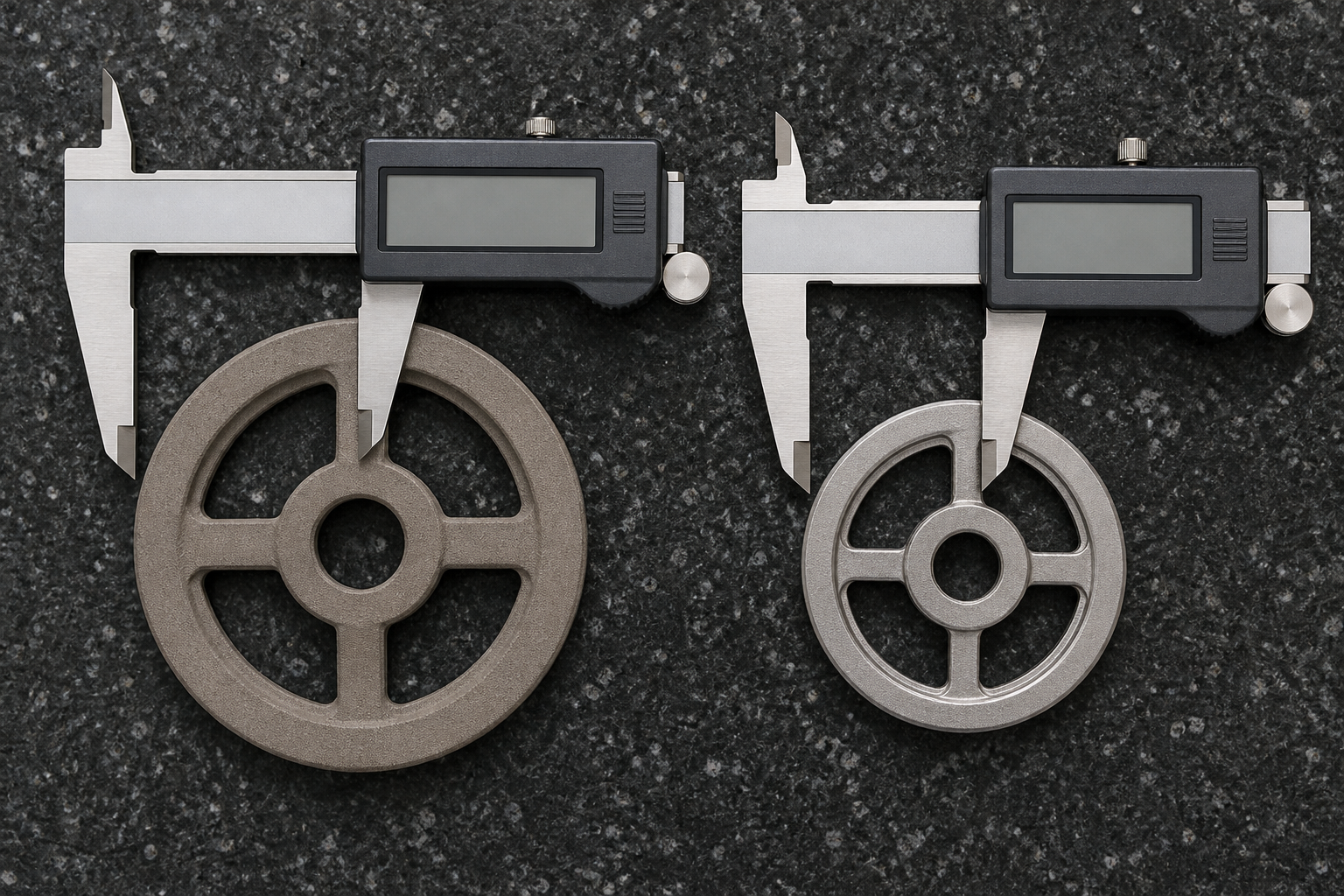
What actually controls the final size
- Feedstock consistency — a change of powder lot or binder ratio shifts shrinkage, so the feedstock is part of the specification, not a consumable.
- Thermal profile — heating rate, hold, cooling rate and atmosphere all affect densification and therefore final dimension.
- Support and fixturing — unsupported spans sag; setter design is a tooling decision that is often discovered too late.
- Distortion versus uniform shrinkage — uniform shrinkage can be compensated in the tool; distortion cannot, and has to be designed out or sized afterwards.
- Sizing and machining — a pressing or coining operation, or a light machining pass, recovers the dimensions that as-sintered tolerance cannot hold.
What Has to Be Verified
Short answer: dimensions alone do not prove a PIM part. A part can measure correctly and still be under-dense, and an under-dense part fails in service without ever failing an inspection.
| Check | What it proves | When it matters most |
|---|---|---|
| Density | That sintering actually achieved the intended densification, not just the intended shape | Every structural or wear application; it is the single most useful process-health indicator |
| Dimensional report against a compensated drawing | That the tool and the sinter cycle together produce the drawing, feature by feature | First article, and after any feedstock or furnace change |
| Mechanical testing | Tensile, hardness or transverse strength, depending on material route | Load-bearing MIM parts; any CIM part where strength is claimed |
| Metallography or microstructure | Porosity, grain size, phase balance, and for ceramics the flaw population that predicts brittle failure | When a failure would be catastrophic, or when a process change needs qualifying |
| Internal flaw inspection | Voids, cracks or inclusions that no surface inspection will find | Safety-relevant parts, and as a development tool where a defect has appeared |
| Surface and appearance | That staining, contamination or handling damage is not being shipped | Visible parts, and any part where corrosion resistance is claimed |
| Traceability to feedstock lot and furnace run | That a later failure can be traced to a batch rather than to the whole programme | Any regulated or customer-controlled programme |
The acceptance criteria belong on your drawing or purchase specification: which dimensions are net-shape, what density or porosity is acceptable, which mechanical properties must be demonstrated and on how many samples. Ask for the method, not just the report — a density figure without the measurement method is not a specification.
Cost, and the Alternatives Worth Comparing
Short answer: PIM is not a cheap process. It is a process that becomes cheap per part when the geometry is complex and the volume is sustained. Quoted as a general advantage — especially as an advantage at low volume — it is simply wrong, and it is the claim most often used to win work that should have gone elsewhere.
| Route | Evaluate it first when | The cost that decides it |
|---|---|---|
| CNC machining | Volume is low, the part is large, or the geometry is simple prismatic | Machine hours and material waste per part; no tool to amortise |
| MIM | Complex small metal part, difficult alloy, sustained annual volume | Tool, feedstock, sinter development and yield, amortised over the programme |
| CIM | Complex ceramic part where net shape avoids diamond grinding | Ceramic powder, firing, and the grinding you avoid or still need |
| Powder compaction | The geometry is simple enough to press in a die, and volume is high | Press tooling and press rate; geometry is the limit, not material |
| Investment casting | The part is larger, or the alloy is one that casts well | Pattern and shell cost, finishing allowance, and achievable tolerance |
| Metal 3D printing | The geometry is extreme, or you need parts before a tool exists | Per-part machine time; it competes on time-to-part, not on unit cost at volume |
The break-even is arithmetical and belongs on your numbers: tool and development cost divided by the per-part saving, over the volume you can actually forecast. A part with a brilliant geometry and a two-year life at low volume is usually a machining job, and saying so costs a supplier one order and earns the next three.
What to Send for a PIM Route Assessment
Short answer: send the drawing as a manufacturing document, not as a shape. The features you mark as net-shape and the ones you allow to be machined after sintering determine both the route and the price.
| Input | What it decides |
|---|---|
| 3D model and 2D drawing with tolerances and datums | Whether the part is net-shape feasible, and which features need post-sinter work |
| Alloy or ceramic specification, including grade | Which route, which feedstock family, which furnace atmosphere |
| Functional versus cosmetic faces | Gate and ejector placement, and the surface that must not be touched afterwards |
| Which dimensions must be net-shape | The split between as-sintered and machined, which is the biggest single cost lever |
| Wall thickness map and the thickest section | Distortion risk and whether the geometry needs redesign before quoting |
| Annual volume and programme life | Whether a tool is economic at all, and over what period it must amortise |
| Post-sinter operations you expect | Heat treatment, grinding, coating or assembly, and who is responsible for each |
| Inspection and documentation requirements | Density method, sampling, reports and traceability that must be built into the process |
| Target date and any known failure of the current process | Whether PIM is the fix, or whether the current defect has a cheaper cause |
The standard commercial inputs — packaging, Incoterms, payment terms and delivery schedule — are handled on our quotation page and are not repeated here.
Frequently Asked Questions
What is powder injection molding (PIM)?
Powder injection molding is a process family in which a fine metal or ceramic powder is mixed with a binder to make an injectable feedstock. The feedstock is moulded into a green part, the binder is removed, and the part is sintered to a dense metal or ceramic component. Metal injection molding (MIM) and ceramic injection molding (CIM) are the two material routes within it.
What is the difference between MIM and CIM?
They share the process sequence but not the material system. MIM uses metal powder and produces a metallic part with the ductility, conductivity and heat treatment response of that alloy. CIM uses ceramic powder and produces a hard, brittle, heat-resistant part. Feedstock formulation, debinding window, sintering temperature and atmosphere, shrinkage, and the inspection methods that matter all differ between them.
How does powder injection molding work?
Six stages: powder and binder are compounded into feedstock; the feedstock is injection moulded into a green part; the green part is debound to remove the binder, leaving a porous brown part; the brown part is sintered in a controlled atmosphere to densify it; and it is then finished by sizing, machining, heat treatment or coating where the drawing requires it.
What materials can be used for PIM?
On the metal side, stainless steels such as 316L and 17-4 PH, low-alloy and tool steels, and special systems such as tungsten heavy alloys and titanium are the common candidates. On the ceramic side, alumina, zirconia, silicon nitride and silicon carbide are typical. Which of these a given plant can actually run depends on its feedstock supply, furnace atmosphere and sintering capability, so the grade has to be matched to the route.
What is the shrinkage of PIM parts?
Large compared with thermoplastic moulding, because the green part is mostly powder by volume with the binder occupying the rest, and the part densifies during sintering. The exact linear shrinkage is a property of that feedstock and that sintering cycle, so it is measured on trials and the tool is cut oversize to compensate. It is not a number that can be applied across materials.
What tolerances can PIM achieve?
As-sintered tolerance depends on the alloy, the part size, the wall thickness distribution, the furnace and the measurement datum. Features that must be tighter than the as-sintered capability are produced by post-sinter sizing, grinding or machining. The realistic split between as-sintered and machined dimensions is decided per drawing, not quoted as a single figure for the process.
Is PIM suitable for small production runs?
Seldom on cost alone. PIM needs a purpose-built tool plus feedstock, debinding and sintering development, so its economics come from complex geometry at a sustained volume rather than from a short run. At low volume, CNC machining or a simpler powder route is normally cheaper. The break-even is set by the tool cost against the per-part saving over the programme.
MIM versus CNC machining: which is better?
CNC wins on low volume, on very large parts, on simple prismatic geometry and where material properties must come from wrought stock. MIM wins where the geometry is complex enough that machining becomes many operations, where the alloy is difficult to machine, and where volume justifies a tool. The comparison belongs on total cost at your annual quantity, not on a preference for either process.
What defects occur during debinding and sintering?
Distortion and sag on unsupported spans, cracking and blistering from too fast a binder removal, residual porosity or low density from an incomplete sinter, dimensional drift from a feedstock or furnace variation, and contamination or staining from the atmosphere. They are controlled by support design, a validated thermal profile, atmosphere control and sectioning or density measurement on trial parts.
What should I send for a PIM quote?
A 3D model and 2D drawing with tolerances and datum scheme, the required alloy or ceramic and its specification, which dimensions are functional and which are cosmetic, the annual volume and programme life, any post-sinter operations you expect, the inspection and documentation you require, and the target date. State which features must be net-shape and which may be machined after sintering.
Related Pages
| Page | What it covers |
|---|---|
| Metal injection molding capabilities | The MIM route in more depth, with the capability statement for the metal side |
| Custom ceramic injection molding | The CIM route, ceramic material options and custom ceramic parts |
| Introduction to the MIM process | Process walkthrough and background for the metal route |
| Powder metallurgy compaction | Press-and-sinter powder compaction, which is a different route from PIM |
| Is injection molding only for plastic? | Where plastic molding ends and powder molding begins |
| CNC machining services | The route to compare against when volume is low or geometry is simple |
| Engineering materials | Material families, grades and property data |
| Quality certifications | Quality system and certification status |
| Manufacturing services | The full process list and how the routes fit together |
Send a Part for a PIM Route Assessment
If the geometry needs many machining operations, or the alloy is expensive as bar, PIM may be the cheaper route — at the right volume. Send the model, the drawing with datums, the material specification and your annual quantity, and the assessment will say which route fits, which dimensions can be net-shape, and whether the volume supports a tool at all.
What this page does and does not claim
This page is a process and route-selection guide. It does not publish equipment counts, capacity, density, shrinkage or tolerance figures for MIM or CIM: those statements belong to the capability pages, and repeating them here would create a second, competing version of the same number.
Equally, it does not claim that PIM is cheaper than other routes. On the contrary, it says where PIM loses — low volume, large parts, simple geometry, tight tolerances on every face — because a buyer who discovers that after a tool is cut does not come back.
Where a figure is needed to answer a real question, the answer is given against a specific part in an assessment. Technical content is reviewed before publication and the page carries a revision date.