Custom Injection-Molded Plastic Parts for Heavy-Duty Applications
Need plastic components that can handle demanding mechanical loads and long-term operating conditions? Goldcattle supports custom injection-molded structural parts, including brackets, mounts, support components and functional assemblies.
We review part geometry, material options, load conditions, mounting features and molding risks before tooling decisions are finalized. Material selection, dimensional requirements and validation scope are confirmed against your drawing and application requirements.
This page is a working reference. The RFQ checklist at the end is shown in full — select the text to reuse it, or use your browser's print / save-as-PDF. Goldcattle does not host downloadable files on this site.
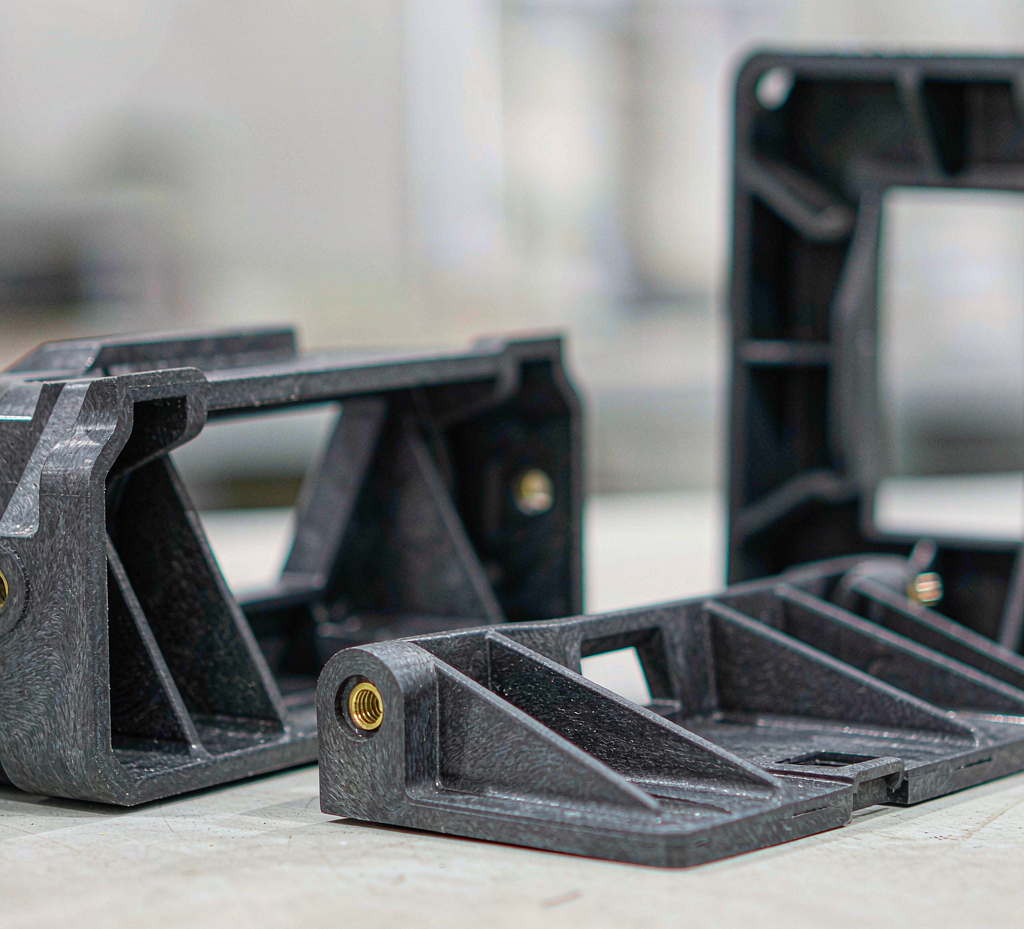
01 · Heavy-Duty Plastic Parts We Manufacture
Heavy-duty means load and durability, not size. We mold structural and load-bearing parts whose function depends on holding dimensions, interfaces and stiffness under real service conditions — grouped below by the engineering role they play.
Brackets & mounts
Load-bearing brackets, mounting plates and equipment mounts that carry assemblies, route loads into structure and keep interfaces aligned.
Bases & feet
Equipment bases, adjustable feet and support pads that transfer machine or assembly weight into floors and frames.
Structural frames
Ribbed frames, chassis parts and support components where stiffness-to-weight drives the design.
Load-bearing housings
Housings that double as structure — carrying internal components, mounting loads and interface forces at once.
Mounting hardware
Bosses, threaded-insert carriers and fastener features designed for repeated assembly and defined tightening loads.
Mechanical moving parts
Guides, slides, cams and functional arms where wear, fit and motion under load matter.
"Heavy duty" is not "large"
A part can be small and heavily loaded, or large and lightly loaded. Large parts are a separate question: they are assessed individually against press tonnage, platen and tie-bar clearance, shot weight and tool size. Send the model and we confirm feasibility from your geometry rather than from a headline range.
02 · Define the Load and Service Conditions First
The same geometry can pass or fail depending on how it is loaded and for how long. Before material or tooling decisions, the load case is defined — because sustained load, repeated load, impact and vibration each drive different failure risks.
| Condition | What it does to the part | What must be defined |
|---|---|---|
| Sustained static load | Deforms the part slowly over time (creep); an initially good fit can loosen | Load magnitude and direction, duration, service temperature |
| Cyclic / fatigue load | Repeated stress accumulates damage; the failure mode differs from static overload | Cycle count, load spectrum, environment during cycling |
| Impact | Sudden energy input; notch-sensitive materials can crack rather than bend | Impact energy, temperature at impact, drop or strike scenarios |
| Vibration | Fastened joints loosen; fatigue concentrates near resonances and mass attachments | Frequency range, mounting conditions, attached masses |
| Elevated temperature | Stiffness and strength drop; creep accelerates well below the resin's rated limit | Continuous and peak temperatures, exposure duration |
| Chemical media & humidity | Some resins absorb moisture or degrade; reinforced PA performance shifts with moisture | Media and concentration, contact time, humidity range |
If the load case is not fully defined yet, send what exists — a load estimate, the mounting arrangement and the service environment are enough to start the engineering review.
03 · Material Selection for Heavy-Duty Injection-Molded Parts
No resin wins on a single property. Material choice works from the load case, temperature, environment and geometry of the specific part — the table below is a screening direction, not a performance guarantee for any grade.
| Material direction | Typical evaluation fit | Limits and factors to confirm |
|---|---|---|
| PA6 / PA66 + glass fibre | Stiffness-driven brackets, mounts, structural frames | Moisture absorption, fibre orientation, anisotropic shrinkage and warp; grade-specific evaluation |
| PBT / glass-filled PBT | Industrial, electrical and mechanical structural parts | Temperature, chemical media, hydrolysis risk, grade and dimensional stability |
| PC / PC blends | Impact-tough structural and support parts | Temperature, chemical compatibility, sustained-load behaviour, moulded stress |
| POM / acetal | Sliding, guide, gear and mechanical moving parts | Shrinkage, friction pairs, service temperature, actual long-term load |
| PPS / PPA / PEEK and other high-performance resins | Specific high-temperature, chemical or otherwise demanding industrial parts | Material cost, processing window, tooling and equipment requirements, real service conditions |
Three selection principles that get missed
1 · Sustained load means creep
Under constant load a plastic part can deform gradually over time without yielding or breaking. Long-term dimensional change can loosen an assembly or degrade function — creep depends on stress, temperature, time and grade, and is evaluated for the actual load case, not the datasheet headline.
2 · Dynamic load is not static strength
Repeated load, impact, vibration and repeated assembly produce different failure risks from a one-time tensile test. Where the part sees them, fatigue, impact or durability verification is planned on the real part and conditions.
3 · Glass fibre is not universal
Adding glass raises stiffness and strength but makes shrinkage directional, and fibre orientation follows flow. On a load-bearing bracket, gate position and flow direction directly affect how the critical region performs — which is why it is flagged at DFM, not discovered at first trial.
Grade-level material detail sits in the materials section; high-temperature resin molding conditions are covered on the PEEK injection molding page. This page stays focused on structural application.
04 · Design for Load-Bearing Injection-Molded Plastic Parts
Structural DFM starts from one question: where does load enter the part, how does it travel through the structure, and where is it finally supported? Every feature below is evaluated against that path — not as a generic molding checklist.
| Engineering question | What the design review establishes |
|---|---|
| Load path | Which surface or mounting point receives the load, what structure carries it, and where it lands on the support |
| Ribs & gussets | Stiffness added without thick sections — avoiding sink marks, warp and local stress concentration |
| Wall thickness | Why carrying load by adding wall alone hits diminishing returns and new defects |
| Mounting bosses | How bosses, fasteners and surrounding structure share the assembly load |
| Metal inserts | When to embed inserts, and how pull-out, torque and positional stability are evaluated |
| Gate & weld line | How gate position, weld-line placement and fibre direction affect critical load-bearing regions |
| Tolerances & interfaces | Hole positions, flatness, axial fit and assembly requirements against mating metal parts |
Mold design and production control for structural parts
For filled structural parts, the mould is part of the engineering — not just the shape-maker. The items below are decided with the part's load case in view.
- Gate position — set to manage fibre orientation, weld-line placement and warp direction in the regions that carry load.
- Fibre orientation — flow direction is reviewed against load direction in critical sections.
- Shrinkage — on filled resins shrinkage is directional; tolerances proven on unfilled parts may not carry over.
- Warpage control — rib layout, wall transitions and cooling balance reviewed together.
- Tool steel & cooling — selected for abrasive filled resin and for uniform heat extraction.
- Cavity consistency — cavity count is a cost and consistency decision for structural parts, balanced per project.
- Insert loading — the loading method is agreed before tooling, with its cycle-time impact priced openly.
Tool development, steel selection and trial stages are covered on the custom plastic injection mold page.
05 · Replacing Metal Parts with Injection-Molded Plastics
Many heavy-duty plastic projects start as metal-to-plastic conversions — an aluminium or steel part targeted for weight reduction, part consolidation or lower unit cost at volume. Plastic does not simply "replace" metal; the conversion re-opens the engineering questions below.
- Real load and safety factor — what the part actually carries, with what margin, over what life.
- Section and load path — the metal part's shape was designed for metal; the plastic part needs its own section and load path.
- Service temperature and creep — sustained load at temperature behaves differently in plastic than in metal.
- Fastening and inserts — threaded connections, boss geometry and insert retention become structural features.
- Assembly tolerances — thermal expansion and stiffness differences against mating parts must be re-checked.
- Validation requirements — the converted part is verified as a part, under its real load case, before production.
For a weight- or cost-driven conversion, the engineering assessment comes before the commercial one — that order is what keeps a converted part from passing inspection and failing in service. Supplier-side programme examples are on the Xiamen Goldcattle injection molding service page.
06 · Quality Control and Validation for Heavy-Duty Plastic Components
Two different questions get answered here: is the part the shape the drawing specifies, and can it do its job under load? Dimensional inspection answers the first; functional validation answers the second — and both are scoped per project.
| Validation category | Considered per project requirement |
|---|---|
| Dimensional & assembly | Critical dimensions, hole positions, position and flatness, assembly fit, insert location |
| Material confirmation | Specified resin grade, filler content, material batch and required material documentation |
| Static load | Deformation, retention or failure behaviour at a defined load |
| Long-term load | Creep, stress relaxation and long-term assembly stability |
| Dynamic durability | Cyclic load, impact, vibration or repeated assembly as the application demands |
| Environmental | Temperature cycling, humidity, specific chemical media or other project conditions |
| Batch consistency | First-article inspection, process records, key-dimension sampling and traceability where required |
Three different levels of evidence
A resin datasheet, a dimensional report on one part, and a demonstrated service life under load are three different things. A material's tensile strength says nothing about the assembled part's load capability — the validation plan states which evidence applies to your part.
Not every part needs every test. The validation plan is built from the failure risk, the product's use and your acceptance specification — and agreed before production, so both sides know what will be demonstrated and what will simply be reported.
Baseline quality process — first articles, dimensional reports, in-process checks and material files — is described on the injection molding services page. This page covers what gets added for load-bearing parts.
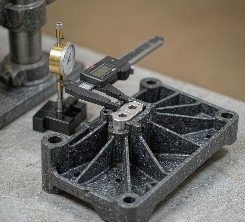
07 · Engineering Review: Glass-Filled Structural Bracket
A representative programme type from our injection molding work — anonymised, with no customer names, part numbers or measured performance figures published. It shows the logic we apply to load-bearing conversions.
| Review item | Detail |
|---|---|
| Application | Load-bearing bracket for a mechanical assembly |
| Design objective | Convert a bracket originally machined from aluminium to a moulded plastic part, for weight and unit cost |
| Material direction | Glass-filled PA, selected for stiffness and strength against the defined load case and service temperature |
| Key engineering risks | Directional shrinkage and warpage on a flat, heavily ribbed part; insert placement accuracy under injection pressure |
| DFM considerations | Rib layout reviewed for uniform wall and balanced orientation; gate position set to manage fibre orientation and warp direction; insert bosses designed with positive location features; tool steel and cooling selected for the abrasive filled resin |
| Tooling & production | Single-cavity production tool with hardened slides and insert loading provisions; insert loading method agreed before tooling, with cycle-time impact priced openly |
| Validation focus | Mounting-point geometry and flatness measured on first articles; insert pull-out performance checked against the requirement |
| Outcome | A moulded part that met the load requirement at lower weight and unit cost than the machined original, produced in the same tool across repeat orders |
On the evidence
No measured performance figures are published for this programme — load values, test data and customer details are shared under NDA during a project evaluation. The value of the example is the problem → judgement → manufacturing → validation sequence, not a result number.
08 · Heavy-Duty Part RFQ Checklist
A heavy-duty inquiry becomes an evaluable project when it carries the eight items below. You do not need all of them to start — for an early design or a conversion study, an existing drawing plus an application description is enough, and the DFM review identifies what else is needed.
| # | Information | What it drives |
|---|---|---|
| 1 | 2D drawing and 3D CAD file | Geometry, wall sections and moulding assessment |
| 2 | Part size & mounting interfaces | Tool size, press fit and assembly conditions |
| 3 | Load conditions — static, dynamic or impact | Material direction, rib and boss design, validation scope |
| 4 | Service temperature, humidity, chemical media | Grade selection and long-term behaviour checks |
| 5 | Specified material or required mechanical performance | Whether the requirement is a grade or a property target |
| 6 | Quantities — first batch, annual, lifecycle | Tool structure, cavity count and batch economics |
| 7 | Acceptance criteria & structural testing needs | The validation plan and what gets demonstrated vs reported |
| 8 | Metal replacement, inserts or secondary assembly | Conversion scope, insert loading and post-mould operations |
Tooling and piece price are quoted separately, and the cycle-time effect of insert loading is priced openly — so the commercial picture matches the engineering one.
09 · Frequently Asked Questions
What qualifies as a heavy-duty injection-molded plastic part?
It is defined by load, long-term service conditions and functional requirements — not by material strength alone or part size. A heavy-duty part carries sustained or repeated loads, must hold dimensions over its service life, and must keep assembly interfaces functional under its actual operating conditions.
Which plastic is best for load-bearing injection-molded parts?
No single plastic. Glass-filled PA, PBT and PC-family materials cover many structural applications, and high-performance resins serve specific temperature or chemical demands. Selection works from the actual load, temperature, environment and geometry — confirmed per project against specific grades.
Can glass-filled nylon replace metal parts?
Sometimes, after engineering review. Metal-to-plastic conversion must compare stiffness, creep under sustained load, temperature, dimensional stability and cost, and the molded part must then be validated as a part — not inferred from resin datasheets.
How do you prevent molded structural parts from warping?
By managing the drivers: uniform wall transitions, rib layout, gate position and fibre orientation, cooling, and mould design. For glass-filled parts, directional shrinkage is designed for at DFM stage rather than corrected at first trial.
How should long-term load be evaluated for plastic components?
Through creep and stress-relaxation behaviour under the actual sustained stress, temperature and time. Sustained load performance is verified against the requirement — datasheet values alone do not describe long-term part behaviour.
Can injection-molded plastic parts withstand repeated impact or vibration?
They can, when the load cycles, environment and expected life are defined and the part is validated against them. Impact and fatigue behaviour differ from static strength, so verification is planned per project rather than assumed.
What affects the cost of heavy-duty plastic injection molding?
Material and filler content, tool structure and steel, cavity count, inserts and their loading method, inspection scope and expected volume. Tooling and piece price are quoted separately, with cycle-time effects of insert loading priced openly.
What information is needed for a custom heavy-duty plastic part quote?
2D drawing and 3D CAD, part size and mounting interfaces, load conditions, service temperature and media, material or mechanical requirements, quantities, acceptance criteria and whether the project involves metal replacement, inserts or secondary assembly.
Can Goldcattle mold large heavy-duty plastic parts?
Size and load capability are separate questions. Large parts are assessed individually against press tonnage, platen and tie-bar clearance, shot weight and tool size; we confirm feasibility from your model rather than quoting a generic envelope.
Have a heavy-duty plastic part to develop?
Send your CAD model, drawing and the conditions the part must withstand. Goldcattle reviews the geometry, material direction, tooling considerations and validation requirements against your project specification.
- Load case reviewed before tooling decisions
- Validation plan agreed with your acceptance criteria
- Tooling and piece price quoted separately, insert loading priced openly

Reviews load cases, structural DFM and validation scope for injection-molded structural parts. Goldcattle has manufactured custom plastic and metal parts since 1998 under an ISO 9001:2015 quality system.