Custom Injection-Molded Plastic Gears for Wear-Critical Applications
Build-to-print molded plastic gears reviewed for gear geometry, material suitability, tooling and molding consistency — then validated against your actual duty cycle. Send the drawing and operating conditions; we evaluate manufacturability, material, tooling needs and production before quoting.
At a Glance
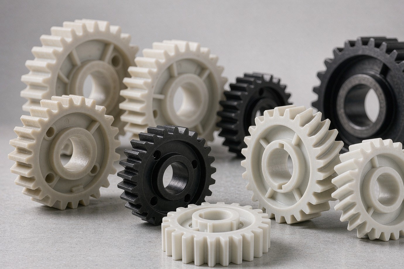
If you need injection-molded plastic gears for a wear-critical drive, the practical path is to send the 2D/3D drawing, the gear parameters and the operating conditions. We review geometry and material against the duty cycle, plan the tool and gate layout, mold and inspect trial gears against the drawing and an agreed limit sample, then run production. Wear is treated as a system result of material, tooth geometry, load, lubrication and mating surface — confirmed for your application, not assumed from a resin name.
Gear Types and Applications
We mold to your drawing rather than to a fixed catalogue. The categories below are how buyers usually specify gears; each carries different geometry, tolerance and assembly requirements that we confirm against the drawing and mating parts.
Spur Gears
The most common molded gear: straight teeth, simple tooling, suited to high-volume drives where noise is not the primary constraint.
Helical Gears
Angled teeth engage gradually for quieter, higher-load meshing; the helix angle and thrust are part of the tooling and bearing review.
Worm & Wheel Sets
High reduction in a compact envelope; the wheel material and lubrication are central to wear performance.
Ring & Internal Gears
Gears cut on the inside diameter for planetary and compact drives; concentricity of the bore to the teeth is the key control.
Small-Module Gears
Fine-pitch gears for instruments, actuators and office equipment, where tooth form and runout dominate the acceptance.
Gears & Housings
Gear plus housing or shaft features in one program, including two-material and assembled gear trains with defined backlash.
Plastic gears appear wherever a light, quiet, corrosion-resistant drive is needed. Typical uses include power-tool and appliance transmissions, automotive actuators and window mechanisms, printers and office equipment, medical and lab devices, and robotics and automation. Each application stresses different things — an actuator gear may care most about impact and temperature, while a printer gear is judged on tooth-form accuracy and quiet running — so we state the engineering focus for your product before quoting.
Material Selection
Choosing Wear-Resistant Materials for Injection-Molded Plastic Gears
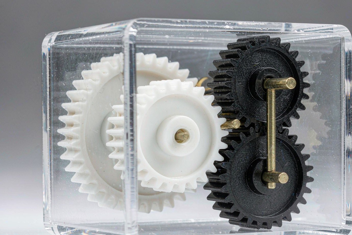
The resin is chosen against the gear's operating temperature, load, speed, lubrication, mating surface and target life — not by a fixed "this material = wear-resistant" rule. The table below groups materials by the dominant failure risk they are usually evaluated for. Specific grades and their data sheets are confirmed at quotation; where a resin has not been qualified in our process for your exact duty, we treat it as an evaluation direction rather than a committed supply.
| Material direction | Common reason to evaluate | Limits and risks | What to confirm |
|---|---|---|---|
| POM / Acetal | Low friction and good dimensional stability for many precision drives | Performance depends on grade, load, temperature, lubrication and the mating material | Actual resin grade, wear duty, gear size and backlash requirement |
| PA / Nylon | Toughness, impact resistance or a different friction response | Moisture uptake can shift dimensions and properties | Dry vs conditioned state, humidity, fit clearance and test condition |
| Wear-modified POM / low-friction compounds | Wear, friction, noise or heat are the main constraints | Performance depends on the modifier and the mating surface, not the "wear" label | Maker grade, material data, friction pair and any validation evidence |
| Reinforced PA / other reinforced polymers | Stiffness, load carry or dimensional stability | Fibre direction, warpage and wear on the mating gear must be assessed | Filler content, tooth accuracy, flow direction and mating-gear wear |
| PEEK / PPS and high-performance polymers | High temperature, chemical or stricter engineering duty | Resin, processing and tooling cost can be higher; not always right for standard volume gears | Working temperature, load, process route, cost and test basis |
Gear Design and DFM
Engineering Wear-Resistant Gears for Injection Molding
We do not quote from outside diameter and tooth count alone. The items below decide whether a gear molds and meshes correctly, and they are reviewed before the tool is cut.
Tooth Geometry & Assembly Interface
Module or diametral pitch, tooth count, pressure angle, helix angle, face width, bore, hub and mating-gear data define the mesh and the manufacturing approach. These are the first things we confirm on the drawing.
Gate, Flow & Weld Line
Gate position, melt flow and weld lines affect how the tooth form and root fill. A poorly placed gate can leave a weld line across a loaded tooth flank; gate and runner layout is part of the tool review.
Rim, Hub & Web
Wall-thickness change between rim, hub and web, plus cooling and shrinkage, drives warpage, concentricity and bore-to-pitch relation. The section is balanced before cutting steel.
Multi-Cavity Consistency
Across cavities we check tooth form, runout, flash, bore fit and mesh — not just the average dimension. Cavity numbering and inspection records help trace batch variation.
Real Meshing & Life Validation
Where wear matters, we prefer to validate against the actual mating gear, bearing, housing, lubrication and load instead of measuring one isolated gear's outside diameter.
What We Need to Review
2D/3D file with version and units, gear parameters, bore/keyway/hub, mating gear and center distance, material grade, duty conditions, and the critical dimensions and tolerances.
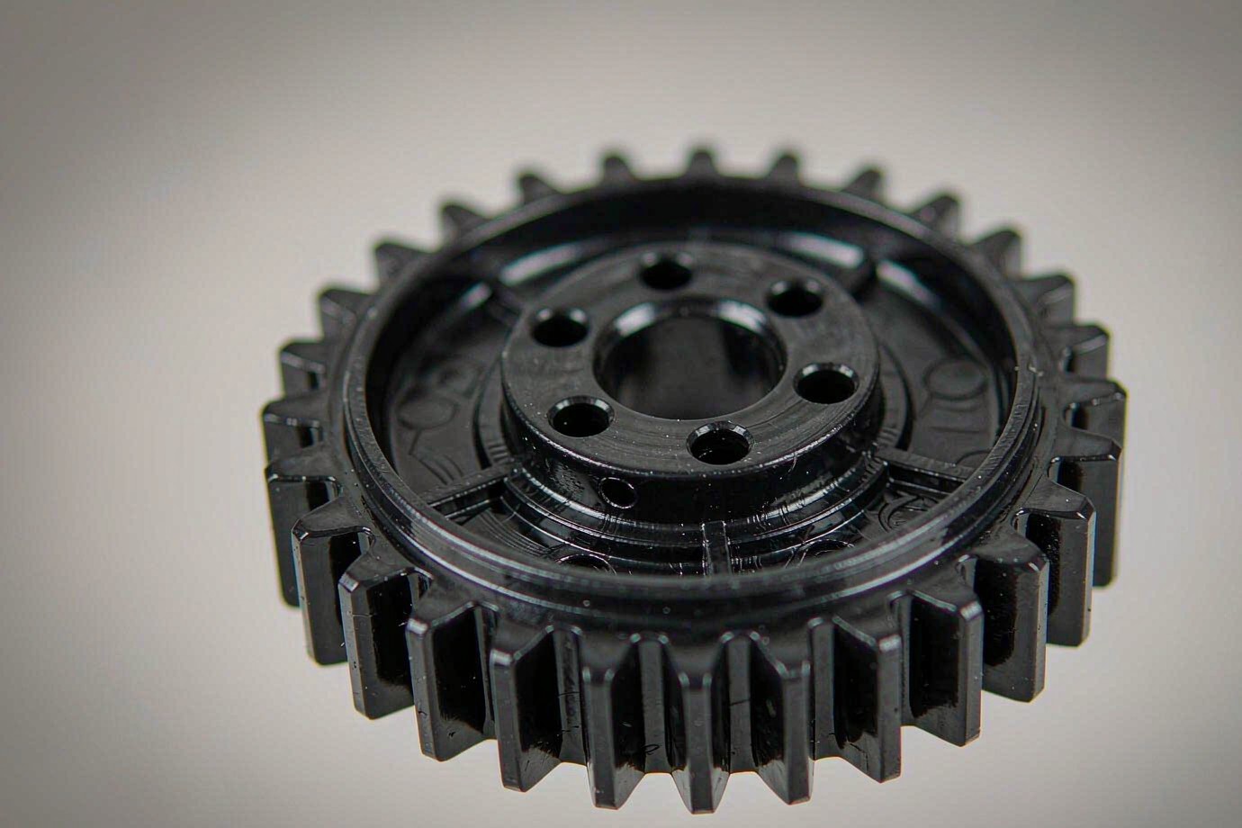
Injection Molding and Tooling
Molding moves the cost and risk into the tool. Gate location, weld lines, shrinkage, warpage and cavity balance are decided during tool design, then confirmed on trial parts. A gear tool is more than a cavity shape: it is gate and runner system, cooling, ejection and, for volume, cavitation and mold life. For the mold-development process and what we build, see our custom plastic injection mold page, and for the wider capability our injection molding services.
| Tooling factor | What it changes |
|---|---|
| Cavitation | Unit cost, tool cost and cycle time — balanced against expected volume and mold size. |
| Gate type and location | Fill pattern, weld-line position and residual stress across the teeth. |
| Cooling and ejection | Warpage, cycle time and bore-to-pitch concentricity. |
| Mold material and life | Tool cost and whether the mold suits the planned production volume. |
| Tolerance and finish | Inspection scope and the agreed limit sample. |
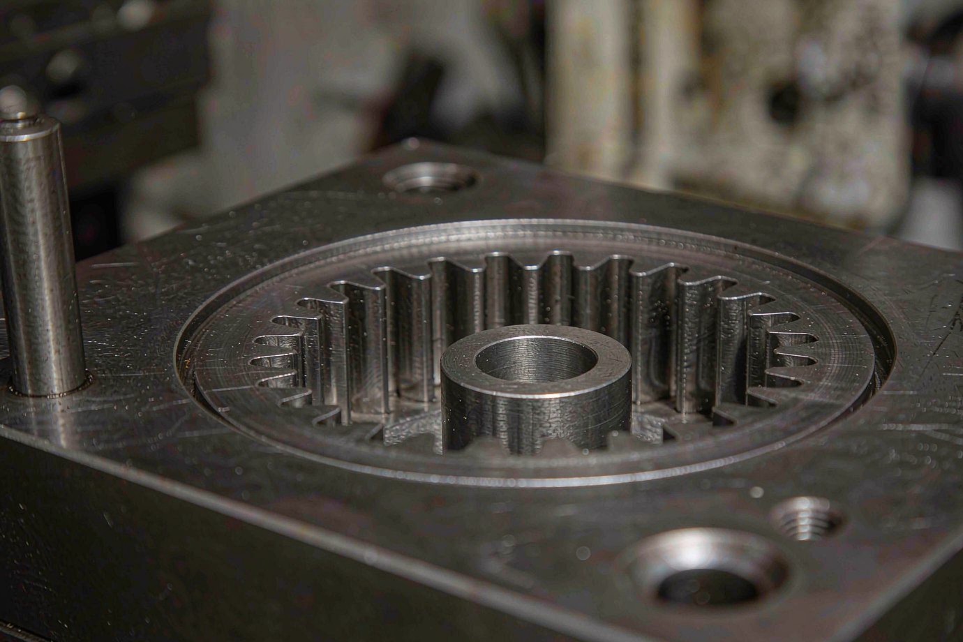
When Should You Choose Injection Molding?
Injection molding is the right route when the design is stable, orders repeat and the tooling investment is justified by volume. It is not automatically cheaper above a fixed quantity — tool complexity, part weight, cycle time, material and order life all matter. We compare routes with you rather than applying a threshold.
| Production route | Best for | Key consideration |
|---|---|---|
| SLS / MJF nylon 3D printing | Prototypes, spares, low-volume and design iteration with no tooling | Material state, surface and gear life must still be validated for the duty |
| CNC machined engineering plastic | Precision prototypes, small batches and gears needing further machining | Cost and speed depend on tooth form, size and batch |
| Plastic injection molding | Stable design, repeat orders where tooling is economical | Shrinkage, tooth form, cavity consistency and process stability must be proven on trial parts |
Inspection and Wear Validation
Molded gears are accepted on two independent dimensions: geometric and assembly inspection, and wear or life validation. They answer different questions and should not be merged into a single "precision gear" claim.
Geometric and assembly inspection
| Inspection item | What is confirmed |
|---|---|
| Tooth profile and pitch | Tooth form, pitch and related geometry against the drawing |
| Runout and concentricity | Tooth reference against the bore, hub or drawing datum |
| Bore and shaft fit | Bore, keyway and interface meet the specified fit |
| Backlash | Gear pair meets target clearance and function after assembly |
| Flash and defects | No flash or defect at teeth, root, parting line or key fitting faces |
| Cavity-to-cavity | Each cavity's sample meets the agreed critical items, not just the average |
Inspection equipment is selected by geometry type, specified tolerance and the quality plan. Some tooth-form and meshing features need applicable gear measurement or rolling inspection rather than a general CMM check alone. AGMA 905-A17 covers inspection methods for molded plastic gears and is a useful reference for measurement approach; it does not by itself set a tolerance grade for your part.
Wear and life validation
For programs where durability is specified, the items below are recorded as applicable — they are chosen per project, not applied to every gear:
- Load, speed and duty cycle of the test
- Test temperature, lubrication and environment
- Mating gear, shaft, bearing and housing as actually assembled
- Gear dimensions, backlash and wear before and after the test
- Indicators such as particles, noise, vibration or temperature rise
- Failure location, test duration and acceptance criteria
AGMA 946-A21 describes wear-test approaches for plastic gears and can serve as a test-plan reference. We adopt a project-specific validation plan where a program is agreed, and report measured results — we do not claim a certified life rating without a performed and documented test.
Project Evidence and Process Capability
Instead of generic claims, we build gear programs on verifiable material: tooling photographs, CAD sections, molded sample gears and inspection records from the actual project. Specific project data — part numbers, dimensions, volumes and test results — is released under a confidentiality agreement after a signed program, so we do not publish customer-specific results as marketing examples.
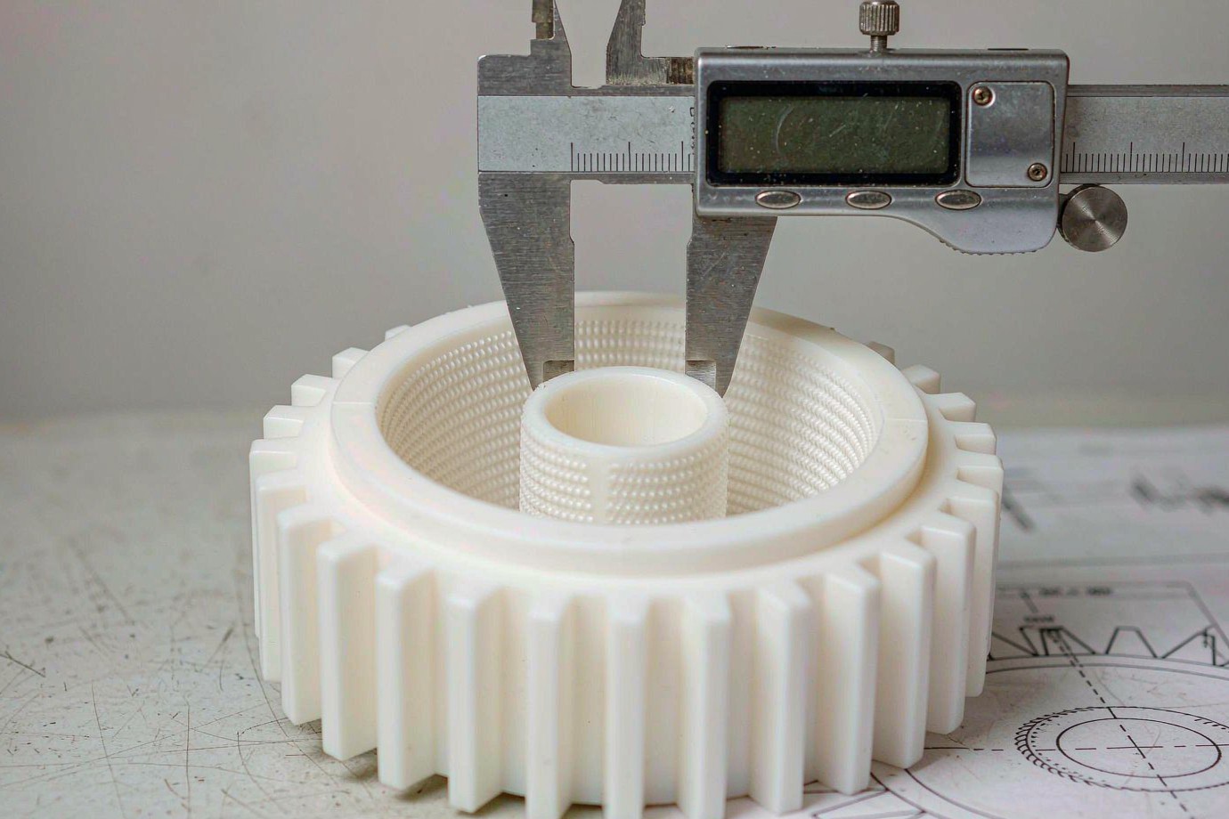
What we prepare for a gear program
- Drawing reviewGeometry, material, duty, tolerances
- Tool planGate, cooling, cavitation, life
- Trial partsMolded and inspected vs drawing
- ValidationMesh and wear plan where specified
- ReleaseAgreed limit sample and records
The gear above is measured during incoming inspection. Real measurement and cavity records — not adjectives — are what we use to show a gear meets the drawing.
RFQ Checklist and FAQ
What Information Is Needed for a Custom Plastic Gear Quote?
You do not need every field completed before contacting us. Send the drawing and whatever you already know; we complete the missing conditions during engineering review rather than rejecting an inquiry for lacking a precise life target.
| RFQ item | What to provide |
|---|---|
| 2D / 3D drawing | STEP, STP, IGES or other CAD file, with version and units |
| Gear parameters | Gear type, module or diametral pitch, tooth count, pressure angle, helix angle if any |
| Fit information | Bore, keyway, hub, mating gear and center distance |
| Material requirement | Resin maker, specific grade, filler, color and material documents if available |
| Duty conditions | Torque, speed, duty cycle, temperature, lubrication, humidity and target life |
| Quality requirement | Critical dimensions, tolerances, backlash, runout, surface and tooth inspection |
| Purchasing need | Sample quantity, initial batch, expected annual volume, repeat plan and target lead time |
| Tooling requirement | Cavitation preference, mold ownership, expected mold life, acceptance and maintenance |
Which plastic is best for wear-resistant injection-molded gears?
Are POM gears more wear-resistant than nylon gears?
Can injection-molded plastic gears replace metal gears?
What causes premature wear in plastic gears?
Are injection-molded gears more economical than 3D-printed gears?
What tolerances can injection-molded plastic gears achieve?
How is wear resistance tested for a plastic gear?
What should I provide for a custom plastic gear quote?
Request a Gear Quote
Send the drawing and operating conditions. We review geometry, material, tooling and production needs, then return a manufacturability assessment and a per-project quotation.
Request a Gear Quote See our injection molding servicesTypical reference: prototype parts about 3–7 working days and production about 15–25 working days after tooling is approved. Actual lead time depends on part complexity, tool build, material and validation scope, and is confirmed at quotation.