Custom – made wear – resistant nylon gear set by 3D printing
| Attribute | Details |
|---|---|
| Materials | PA11, PA12, PA12GB nylon powder; supports ABS/PA66/PP/PC and other plastics/metals |
| Color | Black (custom colors available) |
| Processes | SLS (Selective Laser Sintering), MJF (Multi-Jet Fusion) 3D printing; supports FDM/SLA/others |
| Precision | Tolerance: ±0.005mm, special areas: ±0.002mm |
| MOQ | 1 piece |
| Sample Lead Time | 1-7 days |
| Production Lead Time | 1-30 days (negotiable based on order volume) |
| Surface Treatments | Abrasive polishing, electroplating, vapor smoothing, sandblasting, etc. |
| Application Areas | Industrial gears, automotive parts, aerospace, medical devices, precision machinery |
| Certifications | ISO 9001 |
| Design Support | Accepts 2D/PDF/CAD, 3D/IGES/STEP drawings; offers 3D scanning & reverse modeling |
| Packaging | Carton boxes, wooden cases, pallets (standard size: 15×15×15 cm, weight: 0.35 kg) |
| Shipping Methods | Sea freight, air freight, DHL/UPS/FedEx, etc. |
| Factory Qualifications | 25+ years of experience, 100+ 3D printers (metal/ceramic included), 1,000,000 pcs/month capacity |
| Quality Control | 100% full inspection (CMM, projectors), quality inspection reports provided |
Description
Custom 3D Printed Nylon Gear Sets
Functional nylon gears produced from your CAD, drawing or an existing worn part using SLS or MJF. For prototypes, replacement parts, low-volume mechanisms and applications where complex geometry or rapid iteration matters more than tooling economics.
3D Printed Nylon Gear Set Overview
A gear is a mechanism, not a print job. Whether a 3D printed nylon gear works in your application depends on the gear geometry, the material grade, the load and speed it carries, the temperature it sees and how the tooth mesh is defined. This page covers when nylon additive manufacturing makes sense for gears, what we need to review, and where we will tell you to use a different process.
What We Manufacture
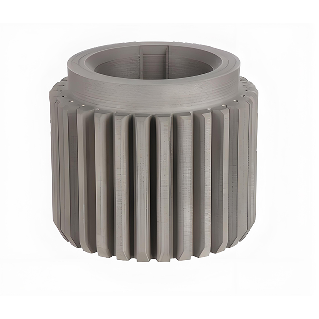
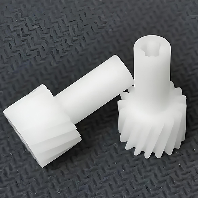
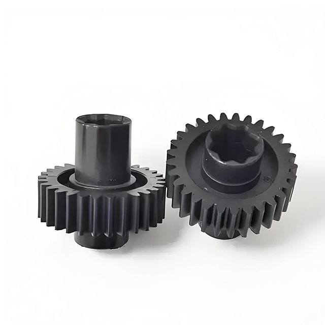
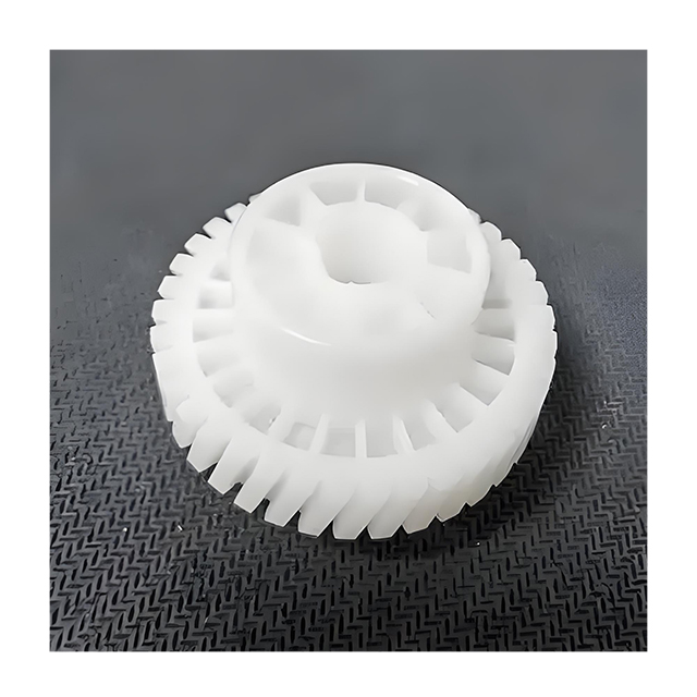
Custom nylon gears in PA11, PA12 and PA12GB, printed by SLS or MJF. Spur, helical, bevel, internal and custom-profile gears for prototypes, replacement parts, functional mechanisms and low-volume production — from your CAD, drawing or an existing worn gear.
Why "Wear-Resistant" Needs Qualification
Wear is not a fixed property of nylon. It depends on material, printing process, tooth geometry, load, speed, temperature, lubrication and the mating gear. We do not claim universal wear resistance — we review the application and tell you what can be validated, and what cannot.
Custom Gear Specifications
Gear parameters, not just outer dimensions, define a functional gear. Each row below is confirmed against your drawing and application.
| Gear Type | Spur / Helical / Bevel / Internal / Custom* |
| Material | PA11 / PA12 / PA12GB* |
| Manufacturing | SLS / MJF |
| Module | Customer-defined |
| Tooth Count | Customer-defined |
| Pressure Angle | Customer-defined |
| Face Width | Customer-defined |
| Bore | Custom |
| Keyway / D-Flat | Custom* |
| Backlash | Application-dependent |
| Color | Black / other options* |
| Quantity | 1 pc to production volume |
| CAD | STEP / STP / IGES / DWG / DXF / PDF |
| Inspection | Dimensional / gear-related per plan* |
* Starred options are confirmed against the gear drawing and the application before production.
Why 3D Print Nylon Gears?
The reason is not "3D printing is strong". It is that additive manufacturing removes tooling and adds geometry freedom, which matters for a specific range of gear jobs.
No Dedicated Tooling
Prototypes, replacement gears, low-volume runs and design iterations happen without a mold investment.
Rapid Iteration
Change the CAD and reprint. The cycle from revision to part is measured in days, not weeks of tooling.
Complex Geometry
Complex gear structures can be produced in a single build, where conventional manufacturing may need multiple steps or setups.
Low-Volume Economics
One piece or a few dozen gears can be produced economically, without absorbing a mold cost.
Part Consolidation
Certain gear assemblies may be consolidated into fewer printed components, reducing assembly steps.
Reverse Engineering
An existing worn gear can be scanned and reprinted without original drawings.
When 3D Printed Nylon Gears Are Not the Best Choice
Knowing when not to recommend a process is part of the engineering review. We will say it plainly.
Very High Volume
Injection-molded gears usually win on unit cost once volume is high enough to justify tooling.
Extreme Load / Speed
Metal gears or proven engineering plastics may be required beyond the practical envelope of printed nylon.
Very Tight Gear Accuracy
If the tooth profile and runout demand machining-level accuracy, CNC finishing or specialized gear manufacturing is the honest route.
Long-Term Qualification
Safety or endurance-critical gears need real testing under defined conditions — a material name alone is not a qualification.
Nylon Materials for 3D Printed Gears
| Material | Typical Advantage | Consideration |
|---|---|---|
| PA11 | Toughness / ductility | Application dependent |
| PA12 | Balanced performance / dimensional behavior | General engineering choice |
| PA12GB | Higher stiffness (glass bead filled) | Abrasion / mating behavior still requires validation |
| Carbon-filled nylon* | Higher stiffness | Surface / friction trade-offs |
| PEEK* | High-temperature performance | High material / process cost |
Moisture and Nylon Gear Performance
Nylon is moisture-sensitive. Moisture content affects dimensional behavior and mechanical properties, and a gear that is dimensionally correct in the print shop may not stay that way in a humid environment unless the design accounts for it.
What Matters
Material storage, drying before processing, ambient humidity at the point of use, dimensional stability and the operating environment all belong in the review.
What We Ask
Where will the gear run, at what humidity, and what dimensional behavior does the mechanism tolerate? These answers change the material and the fit decisions more than "nylon is tough" ever does.
SLS vs MJF for Nylon Gears
| Factor | SLS | MJF |
|---|---|---|
| Supports | Generally not required | Generally not required |
| Complex Gear Geometry | Strong | Strong |
| Production Efficiency | Good | Good |
| Surface | Powder-textured | Typically more uniform* |
| Functional Prototypes | Excellent | Excellent |
| Batch Production | Good | Very suitable |
| Dimensional Behavior | Process dependent | Process dependent |
| Best Choice | Geometry / application dependent | Geometry / batch dependent |
Gear Types We Manufacture
Spur Gears
Parallel shafts, straight teeth, the most common gear form.
Helical Gears
Smoother engagement than spur, at the cost of axial thrust.
Bevel Gears
Change the axis direction between intersecting shafts.
Internal Gears
Assessed against size and printing process capability.
Planetary Components*
Sun, planet and ring gear components reviewed as a set.
Custom Profiles
Produced directly from your CAD or drawing.
Gear Design Parameters We Review
Do not specify only outer diameter and tooth count when requesting a functional gear. A gear that prints is not automatically a gear that meshes.
Module
Tooth size relative to pitch diameter.
Tooth Count
Defines the gear ratio.
Pressure Angle
Standard or custom tooth profile angle.
Pitch Diameter
The reference circle for the mesh.
Face Width
Load-carrying width of the teeth.
Bore / Hub
Shaft interface and hub geometry.
Backlash
Mesh clearance between mating teeth.
Center Distance
Between mating gear centers.
Helix Angle & Keyway
For helical gears and shaft locking.
Backlash and Fit for 3D Printed Nylon Gears
Backlash lets two gears mesh without excessive interference, after accounting for manufacturing tolerance, material behavior and operating conditions. It is not a number to copy from another project.
What Affects It
Print tolerance, gear profile, center distance, thermal and moisture effects, and shaft alignment all contribute to the real mesh condition.
How We Define It
Backlash is set from the gear geometry, the manufacturing process and the operating condition of your mechanism. A backlash value from a published test gear belongs to that test gear, not to your gear.
What Determines Whether a 3D Printed Nylon Gear Will Work?
Material selection alone cannot determine gear life. The chain below is what we review with you before quoting a functional gear.
Common Failure Modes of 3D Printed Nylon Gears
These are the failure modes we design against, and the questions we ask your application.
| Failure | Possible Cause |
|---|---|
| Tooth wear | Excessive friction / load / poor lubrication |
| Tooth breakage | Shock load / insufficient tooth size |
| Hub cracking | Excessive torque / stress concentration |
| Deformation | Heat / load / material behavior |
| Backlash increase | Wear / dimensional change |
| Premature wear | Material / surface / mating gear mismatch |
How We Manufacture Custom Nylon Gears
3D Printed Nylon Replacement Gears
Some of the most valuable gear work we do is not new design. It is keeping old equipment running.
What Fits
Obsolete equipment, discontinued gears, broken teeth, hard-to-source spare parts and legacy machinery where the original supplier no longer offers the part.
How It Works
Existing gear → 3D scan → reverse model → print → test. One working sample is enough to start.
When 3D Printed Nylon Gears Make Sense
Prototypes
Validate tooth engagement, gear ratio, fit and mechanism behavior before committing to a production process.
Replacement Parts
Small batches, obsolete parts, reverse-engineered gears.
Low-Volume Production
Functional quantities without opening a mold.
Mass Production
At sufficient volume, evaluate injection molding, machined engineering plastic or metal. We will say so in the review.
3D Printed Nylon Gear vs CNC vs Injection Molding
| Requirement | 3D Printed Nylon | CNC Machined Plastic | Injection Molded Plastic |
|---|---|---|---|
| 1–5 pieces | Excellent | Expensive | Poor economics |
| 10–100 pieces | Excellent | Good | Tooling consideration |
| 1,000+ pieces | Evaluate | Often costly | Strong candidate |
| Complex geometry | Excellent | Machine-access dependent | Mold dependent |
| Design changes | Very easy | Easy | Tool change |
| Tooling | None | None | Required |
| Surface finish | Process dependent | Strong | Strong |
| Gear qualification | Must validate | Strong | Strong after process validation |
| Lead time | Fast | Fast | Tooling required |
Nylon Gear Quality Inspection
We publish the inspection plan per order, against the agreed specification — not a blanket accuracy claim.
Inspection equipment is applied per the plan — CMM, optical projection and 3D scanning are available and are selected for the features that need measurement.*
Wear Performance Depends on the Application
This page does not claim "wear-resistant nylon". Instead: for wear-critical gear applications, material selection and gear design can be supported by application-specific validation, with test conditions that define load, speed, temperature, lubrication, mating gear material and cycle count.
Applications for Custom 3D Printed Nylon Gears
"May fit" is the honest wording. The final call is made on the load and duty data.
Robotics
Custom geometry and low volume.
May fit — validate load and dutyAutomation
Replacement gears and rapid iteration.
May fit — validate cycle and temperatureSmall Machinery
Lightweight, low-volume mechanisms.
May fit — validate torque and speedLaboratory Equipment
Custom mechanisms and short runs.
May fit — validate precision and dutyPackaging Machinery
Replacement gears and prototypes.
May fit — validate wear and loadLegacy Equipment
Reverse engineering and replacement parts.
Fits — validated against the original partDrone / RC
Lightweight, custom, low-volume.
May fit — validate heat and loadPrototype Mechanisms
Gear ratio and fit validation before production.
Fits — purpose of the print3D Printed Nylon Gear Test Case
The format we use when a customer asks us to validate a gear. The values come from the actual test, not from a brochure.
| Gear Type | Spur / helical* |
| Material | PA12 / PA12GB* |
| Process | SLS / MJF* |
| Module / Teeth / Diameter | Per drawing* |
| Torque / Speed | Per application* |
| Temperature / Lubrication | Per operating condition* |
| Test Duration | Per agreement* |
| Result | Measured wear / failure / dimensional change* |
Before test → running test → after test: measured wear, tooth condition and dimensional change reported against the agreed conditions.
If the customer does not need a test, we quote the gear without one. If the gear is load-critical, we recommend the test and define what it must prove.
We do not publish invented test hours or wear numbers. The table above is the honest format.
Reverse Engineering for Replacement Gears
No drawing, no problem — if you have the part.
Request a Custom Nylon Gear Quote
The more engineering context you send, the more useful the review. A gear drawn from a photo of the mechanism is common — send what you have.
- Gear TypeSpur / helical / bevel / internal / custom
- Module, Tooth Count, Pressure AngleOr the drawing
- Outer Dimensions & BoreOD, face width, bore, hub
- MaterialPA11 / PA12 / PA12GB / other
- QuantityPrototype / replacement / batch
- Application: Load, Speed, TemperatureAnd lubrication if known
- Existing Gear or CADDrawing, STL/STEP, or a sample to scan
- Surface Finish & Inspection NeedsAppearance, report requirements
Gear design review with the parameters checked
Material and process recommendation with the reason
Honest fit assessment for the application
Production quotation with estimated lead time
Inspection plan matched to the order
Frequently Asked Questions
Can you 3D print nylon gears from my CAD file?
Yes. Send a STEP or IGES model, a 2D drawing, or an existing gear for scanning. We review the gear parameters and manufacturing route before quoting.
What materials are used for 3D printed nylon gears?
PA11, PA12 and PA12GB are the common choices, printed by SLS or MJF. The best material depends on load, speed, temperature, moisture, lubrication and the mating gear.
What is the difference between SLS and MJF for gears?
Both are powder-bed nylon processes that need no support structures. SLS and MJF differ in machine, powder and process parameters, and the choice depends on the gear geometry and batch. We select the process for the part rather than claiming one is always better.
Can you print spur, helical and bevel gears?
Yes. Spur, helical, bevel, internal and custom-profile gears can be produced, subject to geometry review and process capability.
What gear parameters do you need for a quote?
Module, tooth count, pressure angle, face width, bore, and where relevant backlash, center distance, helix angle and keyway. A gear that prints is not automatically a gear that meshes, so the parameters matter.
Can 3D printed nylon gears handle real loads?
Nylon gears from SLS/MJF can work in low and medium load applications, but gear life depends on load, speed, temperature, lubrication, mating gear and design. We review the application and tell you honestly whether the gear should be 3D printed, machined or molded.
Are 3D printed nylon gears wear-resistant?
Wear performance depends on the material grade, printing process, gear geometry, load, speed and operating conditions. It is not a fixed property of 'nylon'. For wear-critical applications, testing should define these conditions rather than rely on a general claim.
Can you reverse engineer a broken gear?
Yes. An existing or worn gear can be 3D scanned, reverse modeled into CAD, and reprinted as a replacement.
What is the minimum order quantity?
MOQ is 1 piece, so a single replacement gear or prototype can be printed and validated before any larger batch.
Can I get a prototype before production?
Yes. Prototypes and low-volume batches are the natural fit for 3D printing. Sample lead time is approximately 1-7 days depending on geometry and queue.
When should I use CNC or injection molding instead of 3D printing?
Very high volume points to injection molding; very tight gear accuracy or extreme load may point to machined engineering plastic or metal. We will recommend the route rather than selling one process.
What inspection do you provide for gears?
Dimensional inspection of OD, bore, thickness and hub, gear geometry such as tooth profile and runout where required, plus assembly and fit checks against the application.
How long does production take?
Sample lead time is approximately 1-7 days and production typically 1-30 days depending on volume and geometry. Confirm the schedule at quotation.
Related Services & Guides
Have a Gear to Print — or a Worn Gear to Replace?
Send the CAD, the drawing, or the existing gear. We will review the parameters, confirm the material and process, and come back with an honest engineering assessment and a quotation.