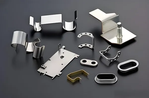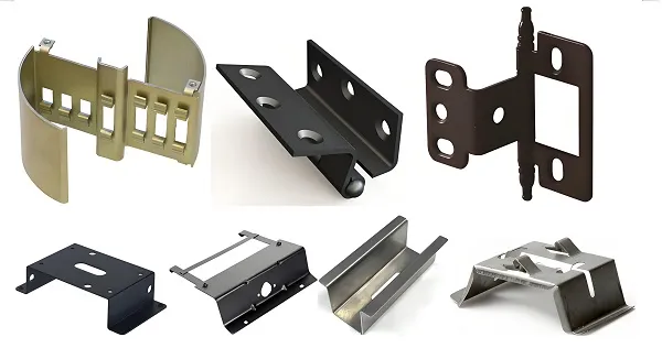
Tight-Tolerance Sheet Metal Fabrication for Custom Precision Components
Cutting, bending, welding and assembly held to feature-level tolerances — defined per operation, verified by measurement, and quoted against your drawing. Built for buyers who need formed parts that actually fit the next assembly.
At a glance
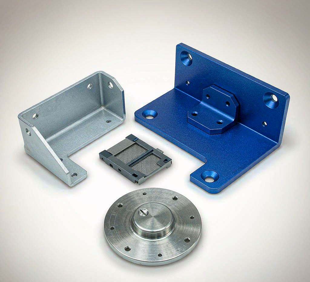
Tight-tolerance sheet metal fabrication means holding specified dimensional limits on cut edges, holes, bends, welds and assembled fits — but those limits are different for every operation. A laser-cut edge, a bent flange and a welded seam each carry their own tolerance band, so we define and verify tolerances per feature and per process, then confirm the achievable values against your drawing before production.
Tolerances by feature
Sheet metal is built through several operations, and each operation has its own natural accuracy. The right question is not “how tight can you go” but “which feature needs to be tight, and how will we hold and measure it.”
Unlike a machined block where one setup controls most dimensions, a formed sheet-metal part accumulates variation from cutting, bending, welding and assembly. That is why we separate tolerances by feature type rather than quoting a single blanket number. The values below are typical reference starting points — the value that applies to your part is confirmed during quotation against the drawing.
Cut dimensions
Reference for laser-cut profiles on common gauges. Tighter cuts depend on thickness, feature size and heat input.
Hole position
Reference for pierced and cut holes relative to datum edges. Small or near-edge holes are quoted per feature.
Bend angle
Reference for air-formed bends. Springback is compensated per material and radius during setup.
Flange / leg length
Reference for bent leg lengths measured from the tangent. Long flanges are reviewed for bow and twist.
Welded fit
General tolerances for welded fabrications, with critical openings machined after welding when needed.
Assembled features
Datums and position controls from your drawing drive how assemblies are located and verified.
Precision laser cutting & hole position
Fiber laser cutting gives clean, dross-free edges and tightly located holes on flat blanks. Dimensional and edge-quality limits follow ISO 9013 for thermal cutting, with tighter values applied where the part and material allow.
Laser cutting is the most repeatable step in sheet-metal work, which makes it the right place to locate features that mate with other parts. We control kerf compensation, lead-in position and micro-joints so profiles stay true to the programmed geometry, and we tab or nest small parts to avoid edge burn on fine details.
- Edge quality: ISO 9013 defines cut-quality classes by underside drag and roughness; we select a class that matches the part’s function.
- Hole position: pierced holes are located relative to cut datum edges; for holes that must sit in a machined bore later, we leave stock and finish them on a CNC mill.
- Heat affect: on thin or reflective materials we tune power and speed to limit the heat-affected zone that can disturb subsequent bending.
For buyers comparing shops: ask whether the quoted tolerance applies to the cut feature or to the finished, bent part. Those are different numbers, and conflating them is the most common source of fit problems downstream.
Precision bending & forming
Bend angle is typically held to ±0.5° and leg lengths to a few tenths of a millimeter, with springback compensated per material, thickness and tooling during the first-article setup.
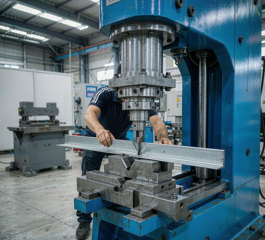
Bending is where sheet metal earns its shape — and where tolerance discipline matters most. A bend is not a single dimension; it is angle, leg length, bend radius and orientation, all interacting. We manage:
Springback changes the angle after the punch lifts, and thin or high-strength materials are least predictable.
We over-bend to a calculated amount, confirm on the first part with a protractor or inspection gauge, and lock the press program.
- Bend-to-edge and hole-to-bend: distance from a bend to a feature shifts as the part forms; we account for this in the flat pattern so the finished location lands in tolerance.
- Minimum bend radius: set by material and thickness to avoid cracking, especially on aluminum and high-strength steel.
- Twist and bow: long legs and asymmetric parts are checked for distortion and corrected with tooling or restrike.
Welding, distortion & assembly
Welded fabrications are verified against ISO 13920 general tolerances for dimensions, shape and position; critical openings are often machined after welding to recover tight features that heat would otherwise shift.
Welding introduces heat, and heat moves metal. For tight-tolerance assemblies the job is to keep that movement predictable and then remove what remains. Our approach:
- Weld sequence & fixturing: joints are planned and clamped so contraction pulls the part toward, not away from, true.
- Tack strategy: tack pattern and size are chosen to control movement before the full weld.
- Post-weld recovery: where a bore, face or mating edge must be tight, we machine it after welding rather than hoping the weld held the dimension.
- Straightness & flatness: checked against ISO 13920 classes selected to match the assembly’s function.
GD&T & tolerance stack-up
A list of ± values does not tell a shop how to build a part. GD&T (per ASME Y14.5 / ISO 8015) defines datums and feature relationships so that cutting, bending and welding all reference the same coordinate story.
Two parts can carry the same ±0.1 mm note and behave completely differently — because tolerance stack-up decides whether the accumulated variation still fits. We read your drawing’s feature-control frames and build to them:
- Datums: we establish the primary–secondary–tertiary scheme your drawing calls out, so every measurement references the same faces.
- Position & profile: true-position and profile controls let a feature float within a zone, which is often the right model for formed parts.
- Stack-up review: on assemblies we check whether the sum of individual tolerances leaves enough clearance, and flag it before production rather than at incoming inspection.
Materials
Common tight-tolerance sheet metals are aluminum 5052 and 6061, mild and high-strength steel, and stainless 304/316, typically across thicknesses from about 0.5 mm to 6 mm. Exact grades and ranges are confirmed per enquiry.
Material choice drives how tightly a part can be held and how it behaves after forming:
Formable, corrosion resistant
Good for brackets and enclosures; bends cleanly, but work-hardens, so radius and springback are planned per thickness.
Stronger, weldable
Used where strength matters; heat from welding can affect flatness, so post-weld straightening or machining may be planned.
High strength, springback
High-strength grades hold shape but need more springback compensation at the brake.
Corrosion resistant
Common for food, medical and outdoor parts; finishes and weld discoloration are managed per spec.
See the full materials overview for grades, available forms and notes on plating and powder coating.
Sheet metal + CNC secondary machining
When a feature must be tighter than cutting or bending can hold, we laser-cut and form the blank, then finish critical holes, pockets or faces on a CNC mill or drill. This hybrid recovers tolerances forming alone cannot reach.
Forming is fast and cheap for shape; machining is precise for features. Combining them is often the most cost-effective route to a tight-tolerance part:
- Tight bores in a bent bracket: cut a pilot, bend, then bore to final size so the hole is true after forming.
- Mating faces and channels: mill flat seats or slots that the brake cannot produce.
- Threads and reamed holes: added after forming to avoid distortion.
For parts that are predominantly machined but include formed features, compare with our tight-tolerance CNC machining capability — the right process mix depends on which features are critical.
Quality inspection & dimensional verification
Verification ranges from pin gauges and calipers for simple features to CMM scanning for critical geometry, all under our ISO 9001:2015 quality system. First-article inspection and dimensional reports are available on request.
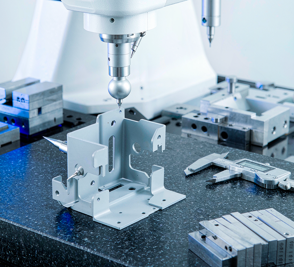
“Tight” is only real if it is measured. Our inspection scales with the part:
- First-article inspection (FAI): the first part off the line is fully checked and used to lock the process.
- In-process checks: bend angle, hole position and flatness sampled during the run.
- CMM reporting: for critical geometry we produce a dimensional report tied to your datums.
- Traceability: material certs and process records kept under ISO 9001:2015.
Products & applications
Tight-tolerance sheet metal is used wherever a formed part must locate, seal or mount against another component — enclosures, brackets, chassis, panels and welded frames across industrial, electronics, automotive and medical equipment.
Mounting and sealing faces
Panels that must align to gaskets, rails and lids with repeatable fits.
Hole patterns that line up
Supporting structures where bolt circles and slots must match the mating part.
Welded, then machined
Rigid structures with critical faces recovered after welding.
Flatness and edge quality
Covers and shields where appearance and fit both matter.
Prototype to production
We support prototypes from 1 piece and scale to production volumes, with lead time depending on part complexity, material and order size. Sampling starts at 1 piece so you can validate fit before committing to a run.
The same drawing drives both prototype and production, so what you validate is what you get:
- Prototype: 1-piece sampling to confirm fit, bend strategy and any hybrid machining.
- Low volume: flexible runs for pre-production and spares.
- Production: repeatable setups with in-process checks and FAI on new lots.
Learn how formed parts sit alongside our broader sheet metal fabrication services.
Case studies
Three representative part types show how feature-level tolerances are actually held — each is summarized without disclosing customer identities.
Electronics enclosure, aluminum 5052
- Critical featureBolt-circle holes
- ApproachLaser locate + CMM verify
- ResultRepeatable panel alignment
A vented enclosure needed matching holes across several panels. We located holes by laser against a common datum and verified the pattern on the CMM so every panel lined up at assembly.
Welded steel bracket, then bored
- Critical featureBore after welding
- ApproachWeld + CNC bore
- ResultTight fit recovered
A welded bracket’s mounting bore would have shifted with heat. We welded the frame, then machined the bore to final size so the shaft fit was held regardless of weld movement.
Formed stainless cover, flatness controlled
- Critical featureSealing face flatness
- ApproachBend setup + check
- ResultGasket-sealing fit
A stainless cover had to seal against a gasket. We set the brake program to control twist and bow, then checked flatness so the cover seated without gaps.
Request a tolerance quote
Send your drawing and we will confirm which features we can hold, to what value, and how we will verify them. The more precisely the critical features are defined, the more accurate the quote.
Request a QuoteXiamen Goldcattle Plastic & Metal Products Co., Ltd. · Founded in 1998 · Quoted to your drawing, not to a generic number.
Frequently asked questions
What tolerance can you hold on laser-cut sheet metal parts?
For most laser-cut features we work to a typical reference of ±0.1 mm on cut dimensions and ±0.1 mm on hole position, but the achievable value depends on material, thickness, feature size and part geometry. Tight values are confirmed per your drawing during quotation.
Is sheet metal tolerance the same as CNC machining tolerance?
No. CNC machining can hold ±0.01 mm on qualified features, while sheet metal is shaped by cutting, bending and welding, each with its own tolerance band. A single 'tight tolerance' number does not apply across processes — tolerances are defined per feature and per operation.
What bending tolerance can you achieve?
A typical reference for bend angle is ±0.5°, with bend-to-edge and flange-length tolerances defined per part. Springback, material thickness and tooling condition all affect the result, so final values are confirmed against your drawing.
How do you control welding distortion in tight-tolerance assemblies?
We control distortion through weld sequence planning, fixture design, tack strategy and stress-relief where needed, then verify against ISO 13920 general tolerances for welded fabrications. Critical openings are often machined after welding to recover tight features.
Do you work to GD&T (ASME Y14.5)?
Yes. We read and manufacture to GD&T callouts per ASME Y14.5 / ISO 8015, including datums, position and profile controls. Send your drawing with the feature-control frames and we will quote to the stated CTQ.
Which materials do you offer for tight-tolerance sheet metal?
Common choices are aluminum 5052 and 6061, mild and high-strength steel, and stainless 304/316, across typical thickness ranges from about 0.5 mm to 6 mm. Exact grades and thicknesses are confirmed per enquiry.
Can sheet metal parts be combined with CNC machining?
Yes. A common approach is laser cut + bent blanks followed by CNC milling or drilling for tight holes, pockets or mating faces that forming cannot reach. This hybrid recovers tolerances that stamping or bending alone cannot hold.
How do you inspect tight-tolerance parts?
Inspection ranges from pin gauges and calipers for simple features to CMM scanning for critical geometry, under our ISO 9001:2015 quality system. First-article inspection and dimensional reports are available on request.
What is your minimum order quantity?
We support prototypes from 1 piece and scale to production volumes. MOQ is 1 piece for sampling; production quantities are quoted per part.
How should I send a request for a tight-tolerance quote?
Send your 2D/3D drawing with the tolerance block, GD&T callouts and any CTQ list, plus material and quantity. The more precisely the critical features are defined, the more accurately we can quote and hold them.
Ready to confirm your tolerances?
Send the drawing and we will tell you, feature by feature, what we can hold and how we will measure it — before you commit to a run.
Discuss Your Tight-Tolerance Part Explore full sheet metal capabilities