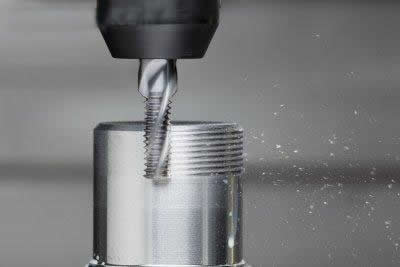
Custom Sheet Metal Fabrication with Powder Coating
The coating is not the part you buy — the interface between fabrication and coating is. What the laser, the brake and the welder leave on the steel decides whether the finish survives; what the booth and the oven do decides whether it was ever cured. This page works through both, and through the drawing details that make the second one possible.
At a Glance
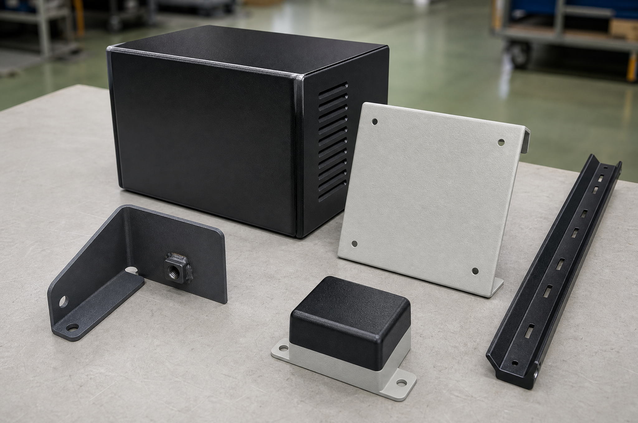
A powder-coated sheet metal part is a fabrication decision that gets judged at the finish. Three things decide whether the coating survives: what the substrate was before it reached the booth, whether the film reached the specified build on the faces that function, and whether the part was cured to metal temperature rather than to a clock. Everything else in the specification is downstream of those three. RAL is a color reference, not a tolerance; a salt-spray hour count is a test result, not a service life.
Powder Coating Is Decided Before the Booth
Buyers usually ask whether a part can be powder coated, and the answer is almost always yes. The useful question is what arrives at the booth, because the finish inherits whatever the previous operations left on the surface, and no pretreatment line reliably removes all of it.
| What fabrication leaves | What it does to the finished coating | Where it has to be solved |
|---|---|---|
| Weld spatter and weld spatter spikes | Powder bridges over the spike and cures as a shell; the shell chips away and leaves a bare crater on a visible face | At the weld: remove spatter before dressing, not after |
| Grinding gouges and coarse scratch patterns | A 60–120 µm film follows the substrate rather than filling it, so every scratch prints through as a shadow line | At deburr: agreed abrasive grade and a final pass in one direction |
| Laser dross and rolled burr on cut edges | The film thins over a sharp edge and cracks there on impact, exposing steel at the most exposed point on the part | At deburr: an edge break on every cut edge that will be handled |
| Mill scale on hot-rolled steel | Powder adheres to the scale, not to the steel; when the scale lifts, the coating leaves with it | Before pretreatment: blast or descale, decided at quotation |
| Cutting and forming lubricant, tapping fluid | Residue survives a weak wash, sits under the phosphate, and produces blistering or patchy adhesion | In pretreatment: wash chemistry matched to the lubricant actually used |
| Weld porosity and pinholes | Trapped air expands during cure and blows a crater through the film | At the weld: porosity is a welding problem before it is a coating problem |
That table is the argument for buying fabrication and coating from one supplier, and it is a better argument than convenience. Every row is a handover point where two suppliers can each be correct and the part still fails — the welder delivered a sound joint, the coater applied the specified film, and the scratch under the paint came from neither of them individually.
The Ten-Step Route
The route below is the one used for coated sheet metal assemblies. The two steps most often missing from a project plan are step 4 and step 7, and both are where rework comes from.
- Nest and laser cut. Parts nested to the sheet, cut on a fiber laser. Kerf quality and dross are set here, and the edges produced here are the edges that will be coated.
- Bend. Press brake forming to drawing, with bend allowance set for the material and the gauge. A bend that is formed after coating is not an option, so any post-coat forming has to be designed out.
- Weld and dress. TIG, MIG or spot as specified, then spatter removal and dressing to the agreed level: a dressed-but-visible weld, a ground-flush weld, or a fully blended seam.
- Deburr and break edges. Every cut edge handled by a person gets a break. This is the step that decides whether the coating survives its first knock.
- Wash and degrease. Alkaline cleaning to remove drawing lubricant, tapping fluid and handling soil. The wash is matched to the lubricant, not to a generic detergent.
- Conversion coating. Phosphate or an equivalent pretreatment appropriate to the substrate, then rinse and dry. This is the layer that carries adhesion and slows corrosion creep under the film.
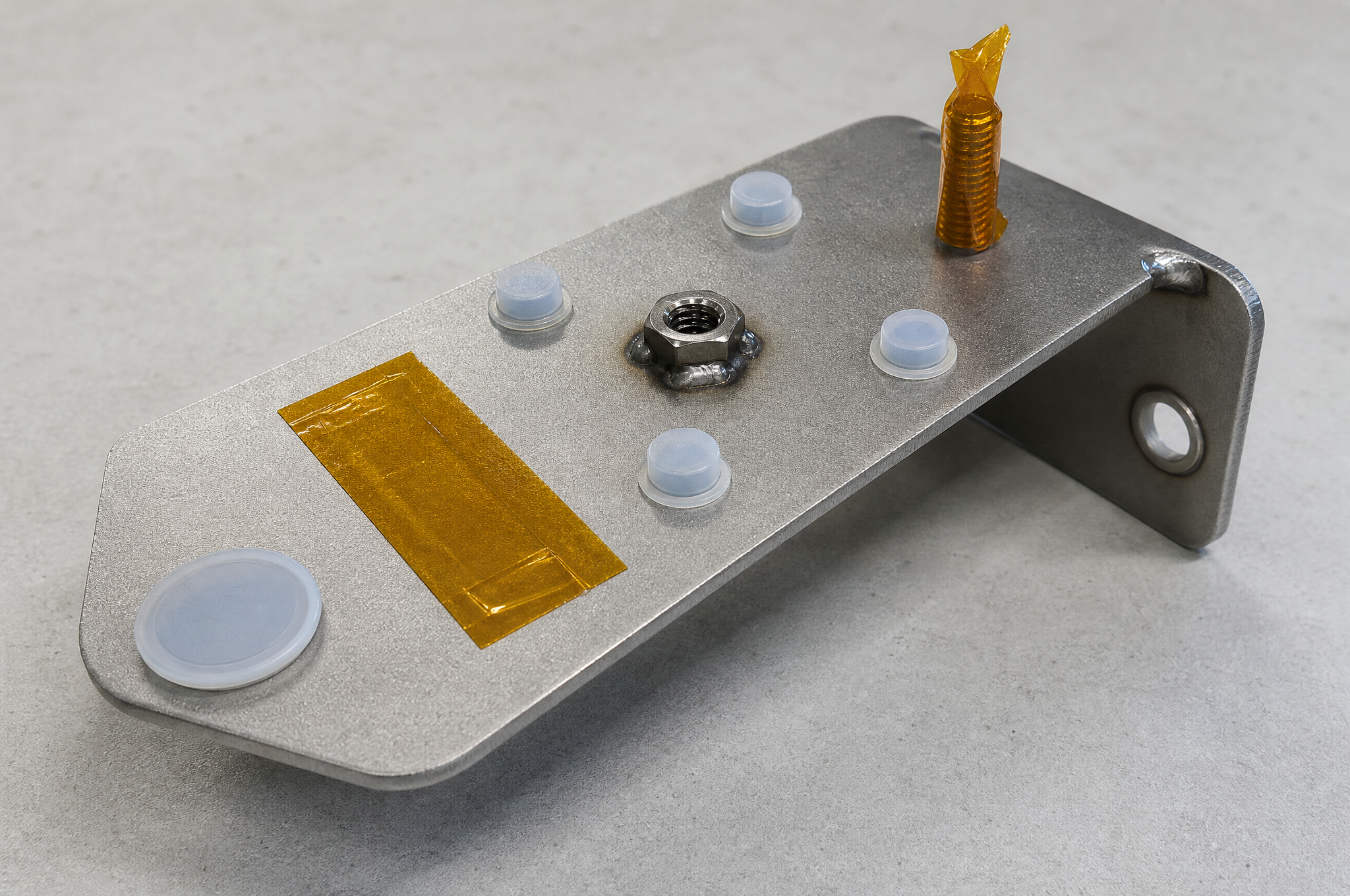
- Mask. Threads, bores, mating faces and grounding pads are plugged or taped to the masking schedule. A missed plug is a filled thread and a rework.
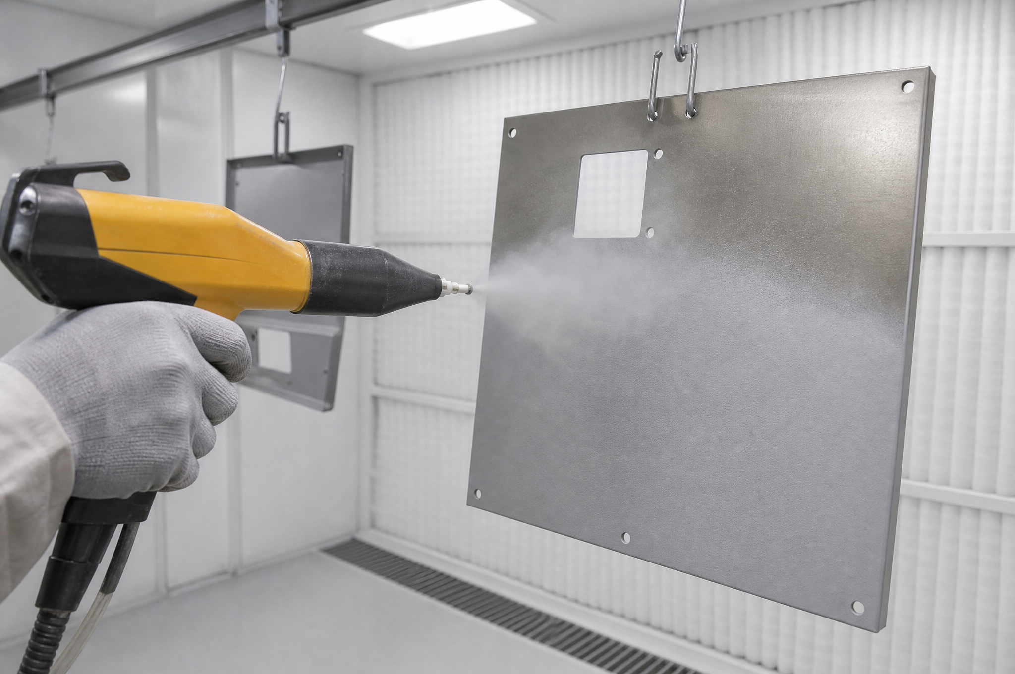
- Rack and spray. The part is hung on a grounded rack and coated electrostatically. The hook contact point becomes a bare spot, so its location is a design decision.
- Cure. The part is brought to the powder's cure temperature for the powder's cure time — metal temperature, not oven setting, and heavy sections take longer to get there.
- Unmask, inspect, assemble, pack. Plugs out, film thickness and appearance verified, hardware and sub-assembly fitted, and the part packed so the coating arrives intact.
Pretreatment Follows the Substrate, Not the Powder
Pretreatment is the part of a coating specification that buyers specify least and argue about most. It is chosen by substrate and by the soil on the substrate, and the same powder over two different pretreatments gives two different coatings. On a coated part the pretreatment layer is typically a few micrometers thick and invisible, and it is the layer that carries almost all of the corrosion performance.
| Substrate | Pretreatment that works | The specific failure if it is skipped |
|---|---|---|
| Cold-rolled steel (CRS) | Alkaline degrease, then an iron or zinc phosphate conversion coating, rinse and dry | Powder over bare, oily CRS has adhesion but no under-film corrosion barrier; the film lifts from a scratch and takes the coating with it |
| Hot-rolled steel (HRS) | Descale first — blasting or acid — then phosphate as above | Mill scale is not steel; the coating bonds to the scale and delaminates in sheets when the scale lifts |
| Galvanized steel (GI) | Degrease plus a pretreatment suited to a zinc surface; cure schedule adjusted for the zinc | Zinc reacts and can outgas under a heavy film, giving pinholes and blisters; a generic phosphate over zinc is unreliable |
| Aluminum 5052 / 6061 | Degrease, remove the natural oxide, apply a chromate-free conversion coating | Entrapped air and moisture in the surface expand at cure temperature and blow small craters through the film; thicker and cast material needs a de-gas bake before coating |
| Stainless steel 304 / 316 | Mechanical key from blasting or an abrasion pass, plus a pretreatment suited to a passive surface; agreed as a project pairing, not assumed | The passive surface is smooth, chemically stable and gives the powder little to grip; adhesion is the risk rather than corrosion |
Two of the rows above are worth more than a line each. On cold-rolled steel the choice between iron phosphate and zinc phosphate is a real one: zinc phosphate grows a heavier crystalline layer and gives more corrosion resistance at more cost and a longer line, iron phosphate is thinner, faster and adequate for a part that will live indoors. Which one a part gets should depend on where the part is going, and it is a question a coater can answer in one sentence if the buyer has stated the environment.
On stainless, the honest position is narrower than most supplier pages imply. Powder coating stainless is possible and is done, but the pairing has to be proven: the surface needs a mechanical key, and the adhesion has to be verified on a sample rather than assumed from the fact that the same powder works on steel. Where a project needs it, we treat it as a new pairing and run a trial.
Writing a Spec That Can Be Inspected
Most powder coating disputes are not about workmanship. They are about a specification that could not be measured, so two reasonable people read the same words and expected different parts. Eight fields close that gap, and each one has a form that can be checked.
| Field | What to write | How it becomes checkable |
|---|---|---|
| Powder chemistry | Epoxy, polyester, epoxy-polyester hybrid or another named system | Named on the coating record, with the supplier's technical data sheet on file |
| Color | A RAL or Pantone reference plus an approved physical standard | Color is judged against the retained panel, not against a code, because the same code from two powder lots is not identical |
| Gloss | A level in gloss units at an agreed angle — commonly 60°, with 85° used for matte finishes | A gloss meter reading, measured on the same face and angle as the standard |
| Texture | Smooth, fine texture or coarse texture, referenced to a sample | Visual comparison against the retained panel; texture cannot be measured in a single number |
| Film build | A range in micrometers, with the measurement location stated | Gauge readings on flat faces away from edges, reported as a set rather than as one figure |
| Pretreatment | The class of pretreatment, by substrate | Process record per batch; visible as adhesion and corrosion performance rather than as a dimension |
| Masking | A marked-up drawing showing every feature that must stay bare | Checked at masking, and again at final inspection, against the same marked-up drawing |
| Acceptance | Which tests apply, on which faces, with pass criteria | Only the tests actually listed are performed; unlisted tests are not implied by the finish name |
"Powder coated, RAL 7016, 60–120 µm" covers three of those eight fields and leaves five open. It is a perfectly normal line on a drawing and it is also the exact line that produces an argument about a part nobody has made wrong.
Film Build: What 60–120 µm Means, and Where It Is Measured
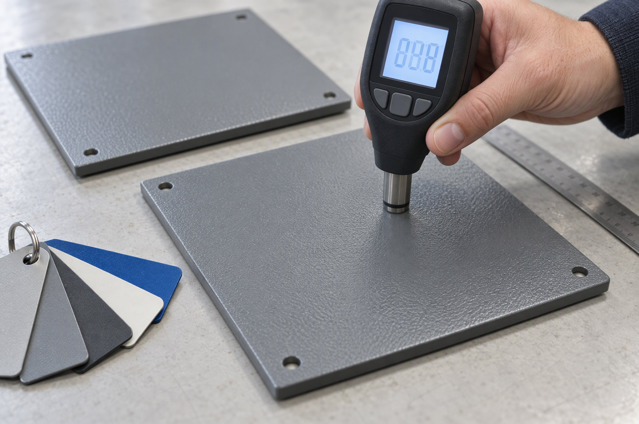
A film thickness range without a measurement location is not a specification, because the film is not uniform across a part. Electrostatic deposition is driven by the field between the gun and the grounded part, and that field concentrates at edges, corners and the outside of a form, while it collapses inside recesses and behind features. The practical results are predictable:
- Edges and corners build heavier than flat faces — often well above the top of the range, because the field lines converge there and the powder is drawn to them.
- Recesses, inside corners and the far side of a flange build lighter, sometimes below the bottom of the range, for the opposite reason.
- The hook contact point builds to zero, deliberately, because the rack has to make electrical contact with bare metal.
So the useful instruction is not "60–120 µm" but "60–120 µm measured on flat faces not less than 10 mm from an edge, five readings per face, reported as minimum, maximum and mean." That is a spec an inspector can execute and a buyer can audit, and it is compatible with a coating system whose non-destructive measurement method follows ASTM D7091 for dry film thickness on metal substrates.
For buyers working in mils rather than micrometers, the 60–120 µm band is roughly 2.4 to 4.7 mil, which is a normal industrial powder build and is not the same as a heavy-duty protective coating system.
Powder Chemistry Against the Environment
Powder is a family of chemistries rather than one product, and the differences that matter to a buyer are ultraviolet stability, chemical resistance and how the finish behaves on a radius. A color choice without a chemistry choice is half a specification.
| System | Strength | Weakness | Where it is the right answer |
|---|---|---|---|
| Epoxy | The best adhesion and chemical resistance of the common powders | Chalks and fades under ultraviolet light; an exterior epoxy will look tired within a few seasons | Indoor equipment, chemical exposure, internal faces, parts that never see sun |
| Polyester | Ultraviolet stability and color retention outdoors | Less chemical resistance than epoxy; some formulations are sensitive to over-cure | Outdoor enclosures, exterior panels, anything with a warranty on appearance |
| Epoxy-polyester hybrid | Good flow and appearance, moderate cost, broad process window | Not an exterior system; ultraviolet performance is limited | General indoor equipment, cabinets and covers where appearance matters more than weather |
| Polyurethane | Appearance and flexibility, good gloss retention | Narrower cure window; more sensitive to substrate and pretreatment quality | Exterior parts that need a premium finish and a tight radius that must not crack |
| Fluoropolymer | Long-term exterior color and gloss retention | Cost, and a demanding cure schedule | Architectural and long-life exterior work where repainting is not an option |
Two specification questions worth asking
Is a durability class being invoked? In the US market, exterior coating performance for architectural metal is commonly specified by AAMA class — 2603, 2604 and 2605 in increasing severity, with 2605 being the most demanding of the three. If your customer's specification cites one, it constrains the powder system rather than the part, and it should be quoted as a system requirement. It is not something to be claimed on a page without the corresponding test data.
Is the crosslinker restricted in your market? Many exterior polyester powders are crosslinked with TGIC, and some markets restrict or discourage it, which is why TGIC-free alternatives exist. If the destination market or the end customer has a substance restriction, say so at RFQ rather than after the powder is ordered — it is a substitution, not a coating parameter.
Four Failure Modes, and How to Tell Them Apart
Coating failures look similar in a photograph and are completely different in cause, which is why they get misdiagnosed. The useful thing to know is that three of the four are decided before the part reaches the booth.
| Failure | What it looks like | Root cause | Where it was preventable |
|---|---|---|---|
| Adhesion loss and under-film corrosion | Coating lifts in sheets or flakes from an edge or a scratch, often with rust already spread beneath it and a clean metal surface underneath | Contaminant under the phosphate, a phosphate too thin to do its job, or an under-cured film that never developed its adhesion | Pretreatment and cure — both process, neither visible on the finished part |
| Outgassing craters | Small volcanoes with a bare or thin center and a raised ring of coating, often clustered near a weld, a casting skin or the gate area of a casting | Air or moisture trapped in the substrate expanding suddenly at cure temperature and punching through the softening film | Substrate choice and the cure ramp; thick or porous material may need a de-gas bake before coating |
| Edge and corner failure | Bare metal or a fine crack along a cut edge or a fold, visible after handling or a light impact | A sharp edge or rolled burr that the film cannot cover evenly, and a film too brittle at that geometry | Deburr and edge break at fabrication; film build and powder flexibility at specification |
| Color and gloss drift | Parts from one batch do not match a previous batch, or whites yellow and gloss drops on parts that look otherwise perfect | Different powder lots, different film build on a textured powder, or a part that spent longer in the oven than the powder allows | Lot reservation and cure records; a retained physical standard instead of a code alone |
The three-second diagnosis
A crater has a thin or bare center and a raised rim, and the rim is coating, not rust. A blister from under-film corrosion has no raised rim of its own and almost always originates at an edge, a scribe or a fixing hole where moisture entered. A chip from impact has a fracture edge with the coating still at full thickness around it and no rust underneath, because it happened recently. Those three observations separate a substrate problem, a pretreatment problem and a handling problem, which is the difference between fixing the process and re-coating the same bad part.
What Powder Coating Cannot Do
The limits are worth stating plainly, because a supplier who claims the opposite will be found out on the first project where it matters.
- It does not fill or hide anything. At 60–120 µm the film follows the substrate. A scratch, a grinding swirl, a weld ripple and a laser striation all remain visible, softened but present. Surface quality has to be produced at fabrication, not bought at the booth.
- It is not a tolerance process. You cannot hold a close dimensional tolerance through a coating operation, because the film is not uniform and its local value is not known until it is measured. Anything that needs a tight fit across a coated face has to be masked, allocated for, or machined afterwards.
- It is an insulator. A powder film is a dielectric. Anywhere electrical continuity is required — a grounding stud, an earth boss, an EMI gasket land, a bonding point between two coated panels — the coating must be omitted or removed, and a coated joint is not a bonded joint.
- It is not invisibly repairable. A touch-up stick or an aerosol never matches: the texture and gloss differ even when the color is close, and the repair is visible at an angle. A proper repair means stripping and re-coating, and stripping is not free — chemical or thermal removal changes the substrate surface and it has to be pretreated again.
- It is not a substitute for a galvanized substrate in a severe environment. A powder film over cold-rolled steel, specified and built as a decorative and moderate-protection system, is not the same as a duplex system on galvanized steel. Where the environment is aggressive, the substrate and the system both change.
- It cannot be applied over an assembly that will not survive the cure. Seals, gaskets, plastics, adhesives and electronics go on afterwards, and that decision changes the assembly sequence rather than the coating.
Masking, Threads and Contact Points
Masking is where a coating specification becomes a manufacturing instruction, and it is the part of a coating job that most often arrives incomplete. The masking schedule is a marked-up drawing: every feature that must remain bare is marked, and everything not marked gets coated.
| Feature | Why it has to stay bare | How it is usually protected |
|---|---|---|
| Threaded holes and studs | A 60–120 µm film on a thread flank destroys the fit; a plugged hole loses the thread entirely | Silicone push-in plugs and caps, or high-temperature tape on a stud |
| Grounding and bonding points | The coating is a dielectric, so a coated pad is not an electrical connection | Taped pad, later fitted with a star washer or a bonded stud |
| Precision bores and bearing seats | Film consumes the interference and the bore is no longer round | Caps; where the tolerance is tight, the bore is machined after coating instead |
| Mating and split lines | Two coated faces touching bind, chip and show a bright line where they rub | Mask one side of the joint, or allocate clearance for both films |
| EMI gasket lands and shielding contacts | The gasket must contact bare metal to conduct | Masked land, or a masked land plus a conductive gasket |
| Hinge and latch interfaces | Film thickness changes the fit and the hinge stops closing to its designed position | Mask the knuckle bore and the latch strike, coat the rest |
Mask it, or cut the thread back afterwards
Two more masking facts that surprise buyers. First, the hook leaves a mark: the rack contacts bare metal by definition, so there is one small uncoated spot per hanging point. Put it where nobody will look — the inside of a return flange, a face that will be covered by another part — and put that decision on the drawing, because the painter will otherwise choose for you. Second, two-tone work is labor, not powder: masking a part for a second color is a manual operation on both passes, and it is one of the few finishing costs that scales with part complexity rather than with size.
Dimensioning a Part That Will Be Coated
The whole chapter can be reduced to one line on the drawing: are these dimensions before coating or after? Most sheet metal drawings are before coating, because that is how the part is fabricated and inspected at the bench. That is fine, provided every dimension that has to be correct after coating is identified and dealt with.
| Feature | What the film does to it | The three available answers |
|---|---|---|
| A hole that takes a pin or a fastener | The bore closes by roughly two film thicknesses, and not evenly around the circumference | Mask the bore; open the pre-coat hole by the expected film; or drill after coating |
| A thread that must engage fully | Film on the flank reduces engagement and increases assembly torque | Mask, or chase the thread (with the corrosion trade-off above) |
| A boss or a lid that seats in a rebate | Film on both mating surfaces closes the gap by the sum of two films | Allocate clearance for two films, or mask one face |
| A flat sealing face with a gasket | Film thickness variation becomes gasket compression variation | Mask the land, or specify the flatness of the coated face and accept it |
| A butt joint between two coated panels | The visible gap closes and the panels touch, chipping at the seam | Design a gap wider than two maximum films, or mask the visible edge of one panel |
Where a dimension has to survive coating, allocate from the top of the specified build rather than from the nominal, because the local film on the face in question may be anywhere in the range — and on an edge or a tight outside radius, above it. There is no single allowance that can be quoted from a table: the film on a given face depends on geometry, rack position and gun angle, which is exactly why the film build specification has to state where it is measured, and why masking is often cheaper than arithmetic.
Inspection, and What Salt Spray Hours Do Not Prove
What gets inspected on a coated part should be the short list that the specification actually named. The four checks below cover most industrial sheet metal work; each one is only meaningful with its method and its acceptance criterion attached.
| Check | Method | What it proves — and what it does not |
|---|---|---|
| Dry film thickness | Non-destructive magnetic or eddy-current gauge, readings on flat faces away from edges, following ASTM D7091 | Proves the film reached the specified build where it was measured. Does not prove coverage inside recesses, on edges, or on the faces nobody gauged |
| Adhesion | Cross-cut or tape test to ASTM D3359, or cross-cut classification to ISO 2409 — they are different systems with different rating scales and cannot be quoted interchangeably | Proves the bond to the substrate at the test location. Does not predict long-term performance under a chemical or a thermal load |
| Appearance | Visual against a retained physical standard, plus gloss meter at the agreed angle and a color reading where specified | Proves batch-to-batch consistency against that standard. Does not prove a match to a code that was never converted into a physical standard |
| Corrosion resistance | Salt spray to ASTM B117 or neutral salt spray to ISO 9227, where the project requires it | Proves a comparative result under one accelerated condition. Does not prove service life, and does not transfer to a different environment |
Why a salt spray hour count is a weak claim
Three reasons, all of them ordinary practice rather than pedantry. First, ASTM B117 and ISO 9227 are test methods: they define the apparatus and the procedure, and they deliberately do not define how many hours a coating must survive, because that depends on the system and the application. Second, the number of hours does not convert into years of service — an accelerated chamber compresses some mechanisms and distorts others, and a part that passes a long test can still fail in a real environment with a different chemistry. Third, and least often mentioned, the meaningful measurement on a scribed panel is the corrosion creep distance from the scribe, not the percentage of red rust on the face. A report that gives hours and a rust percentage without a scribe creep allowance is not reporting the thing that matters.
So a defensible statement reads: tested to this standard, for this many hours, scribed / unscribed, with this creep allowance, on this substrate and pretreatment. Anything shorter is a marketing number.
Documents a coated batch can carry
| Document | What it records | When it is issued |
|---|---|---|
| Material certificate | Substrate grade and heat or lot | Per batch, against the drawing |
| Coating record | Powder product and lot, color reference, cure temperature and time | Per batch, so a color or cure question can be traced later |
| Film thickness report | Readings with locations, minimum, maximum and mean | Per batch or per sampling plan |
| Adhesion result | Method, rating, and the sample used | First article and periodic audit |
| Dimensional report | Critical dimensions after coating, against the drawing | First article and per sampling plan |
| Retained color standard | A coated panel of the approved color, gloss and texture, kept by both parties | At approval, and re-made only when the powder lot changes |
| Packaging record | Interleaving and protection used for the shipment | Per shipment |
What We Fabricate and Coat
The parts below are the shapes that come through this route most often. What they have in common is a coated face that someone will look at or touch, and a set of features behind it that must not be coated.
Industrial Equipment Enclosures
Folded and welded housings in 1.5–2.5 mm CRS or aluminum. Coated inside and out where the interior is visible on opening, exterior only where it is not — and the flatness of the door face is the feature that shows every fabrication mark.
Electrical Control Cabinets
Body and door fabricated as separate assemblies so they can be coated and then hung. Earth studs, gland plate openings and hinge bores are masked; the gasket channel is coated so the gasket seats on a sealed surface rather than on bare steel.
Chassis and Cabinet Frames
Multi-piece welded structures with internal rails and mounting patterns. Usually coated as a complete assembly, which means the rack has to carry the whole frame and the masking has to cover every rail thread in one pass.
Metal Panels and Front Plates
1.0–2.0 mm sheet with a class-A face. The single most common defect on a flat coated panel is not the coating: it is a grinding swirl or a laser striation that the film faithfully reproduces.
Brackets and Mounting Plates
Laser-cut, bent, often with a welded nut or a PEM insert. Threads plugged before coating; where the thread is chased afterwards instead, that decision is recorded so the corrosion trade-off is a known one.
Welded Frames and Skids
Tube, angle and sheet gussets welded into a rigid frame. Weld dressing level is agreed per face: a dressed-but-visible weld on a structural face, a blended seam on a visible one.
Machine Guards and Perforated Covers
Mesh, expanded metal or perforated sheet in a frame. The open area is where film over-build happens first, because the field concentrates on every strand — guard openings close up if the build runs away.
Covers, Cowlings and Fascia
Thin gauge over a large flat area, which is the hardest combination to coat invisibly: any oil can, any wave in the sheet and any tool mark reads as a highlight under a satin film. These are quoted with the surface requirement stated.
Capability for the fabrication steps behind these parts — fiber laser cutting, press brake forming, turret punching, TIG and MIG welding, hardware insertion — sits on the sheet metal fabrication services page, and the stainless variant of the same work is covered under stainless steel sheet metal enclosures. Substrate properties are in the materials guide.
What Drives the Cost of a Coated Part
Coating cost is often quoted as a rate per square meter, which is a reasonable starting point and a poor predictor. The drivers below are the ones that move a real quotation.
| Driver | Why it moves the price | Where there is room to trade |
|---|---|---|
| Part size against rack capacity | A large part occupies a rack position that could hold several small ones, so labor per part is nearly constant while output per hook is not | Split a large assembly into coated sub-parts only where the split is not visible after assembly |
| Masking count | Every plug and tape strip is applied and removed by hand, twice per part in the case of a two-tone job | Reduce hole count, or accept chasing a thread instead of plugging it |
| Pretreatment class | Descaling, blasting or a de-gas bake adds a step before the line | Specify hot-rolled only where its thickness is needed; cold-rolled usually needs less pretreatment |
| Powder system | Standard polyester and epoxy are commodity; a special-effect, fluoropolymer or TGIC-free exterior system is not | Reserve premium systems for the faces that will actually see weather |
| Color changes and batch size | A booth cleaned down for a short run of a special color pays for the changeover in that run | Consolidate colors across a program, or accept a standard stock color |
| Rework risk | Stripping and re-coating a cured part costs more than coating it, and stripping changes the substrate | Complete the masking schedule and the finish standard before the first part is cut — the cheapest rework is the one designed out |
| Inspection scope | Film thickness per batch is fast; adhesion and salt spray are sample-based and slower | Match test frequency to the risk, and put it in the quality agreement rather than per order |
What to Send With a Coated Sheet Metal RFQ
The fabrication data gets you a manufacturing price. The finishing data gets you a finish that can be inspected — and both come out of the same RFQ if the RFQ is written once.
| Send this | Why it changes the quote or the process |
|---|---|
| 3D model and a dimensioned 2D drawing | Geometry from the model, tolerances and finish notes from the drawing |
| Substrate and thickness per part | Sets the pretreatment class and whether descaling is needed |
| Fabrication notes: weld dressing level, edge break, visible faces | These are the operations that decide whether the coating can look right |
| Powder system, or the environment it must survive | Indoor, outdoor, chemical, coastal — the chemistry follows from it |
| Color reference and a physical standard or approved sample | A code alone cannot be inspected; a retained panel can |
| Gloss target and texture | Matte, satin or gloss, and smooth versus textured, change both the look and the film behavior on edges |
| Film build with the measurement location | Without a location the range cannot be checked |
| Masking schedule — a marked-up drawing | The single most useful finishing document, and the one most often missing |
| Which features are functional after coating | Holes, threads, mating faces and grounding pads that must work as coated |
| Required standards and test scope | Film thickness, adhesion, salt spray — named, with acceptance criteria |
| Quantity and call-off pattern | Color changes and rack setup are amortized across the run, not the order line |
| Whether assembly, hardware or packaging follows coating | Determines curing and handling, and what has to be protected before shipment |
| The existing part, if this is a replacement | Where the old coating failed — chipped edges, craters, peeling from a scratch — usually identifies the fix in one line |
Frequently Asked Questions
What is powder coating and how does it differ from wet paint?
Can you powder coat welded sheet metal assemblies?
What film thickness should I specify?
How thick is powder coating in mils?
Which powder is best for outdoor parts?
Can you powder coat stainless steel?
How do you protect threads and grounding points during coating?
Does powder coating change the part dimensions?
How do you check powder coating quality?
What do salt spray hours actually prove?
Can I get a color match to a RAL number?
What information do you need to quote powder-coated sheet metal parts?
Request a Quote for Coated Sheet Metal Parts
Send the drawing, the substrate, the color reference and a masked-up view of what must stay bare. We will come back on pretreatment, film build, masking and inspection scope — before the first sheet is cut.
Request a Coating QuoteSTEP, DXF, DWG or PDF drawings. Prototypes through repeat production.
See all manufacturing services →