5-Axis CNC Machining for Complex Undercuts: Tool-Access Engineering, Not Just More Axes
An undercut is a feature a straight 3-axis tool path cannot reach — a groove inside a blind hole, a side pocket, a dovetail. We resolve them with the right combination of specialized tooling, 3+2 indexing and simultaneous 5-axis motion, chosen per feature rather than by default. Here is how the access problem is actually solved.
At a glance
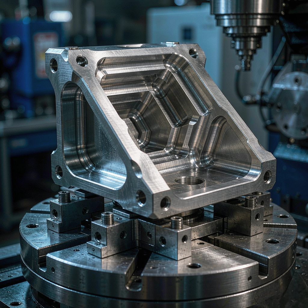
An undercut is any feature whose cross-section is wider — or offset — behind a narrower opening, so a straight tool fed along one axis cannot form it. A 3-axis mill often can make undercuts with the right dedicated tool; 5-axis earns its place when geometry, not tooling, blocks access. We select between 3-axis with specialized cutters, 3+2 indexing and simultaneous 5-axis per feature, then prove clearance in CAM before the first chip is cut. We do not assume every undercut needs simultaneous 5-axis.
What is an undercut in CNC machining
Most machined features are "draft" features: a pocket, a bore or a slot whose walls can be reached by a tool descending straight down and swinging in the XY plane. An undercut breaks that rule — the cutting volume sits behind an overhang, a lip or a narrower neck, so the tool shank or holder collides with the opening before the flutes can reach the cut.
This is why undercuts are an access problem before they are a tolerance problem. Three things decide whether a feature is machinable as drawn:
Neck geometry
If the widest part of the cut is behind a narrower mouth, a straight tool cannot clear the neck and still reach the volume.
Holder clearance
Even a thin cutter needs a shank and holder; both must fit through the opening and not strike the wall.
Line of sight
Where the cut sits at an angle or on a rotated face, the only clean approach is to tilt the tool or turn the part.
Verify, not assume
Internal undercut features must also be measurable — a feature you cannot probe is a feature you cannot certify.
Five common undercut types
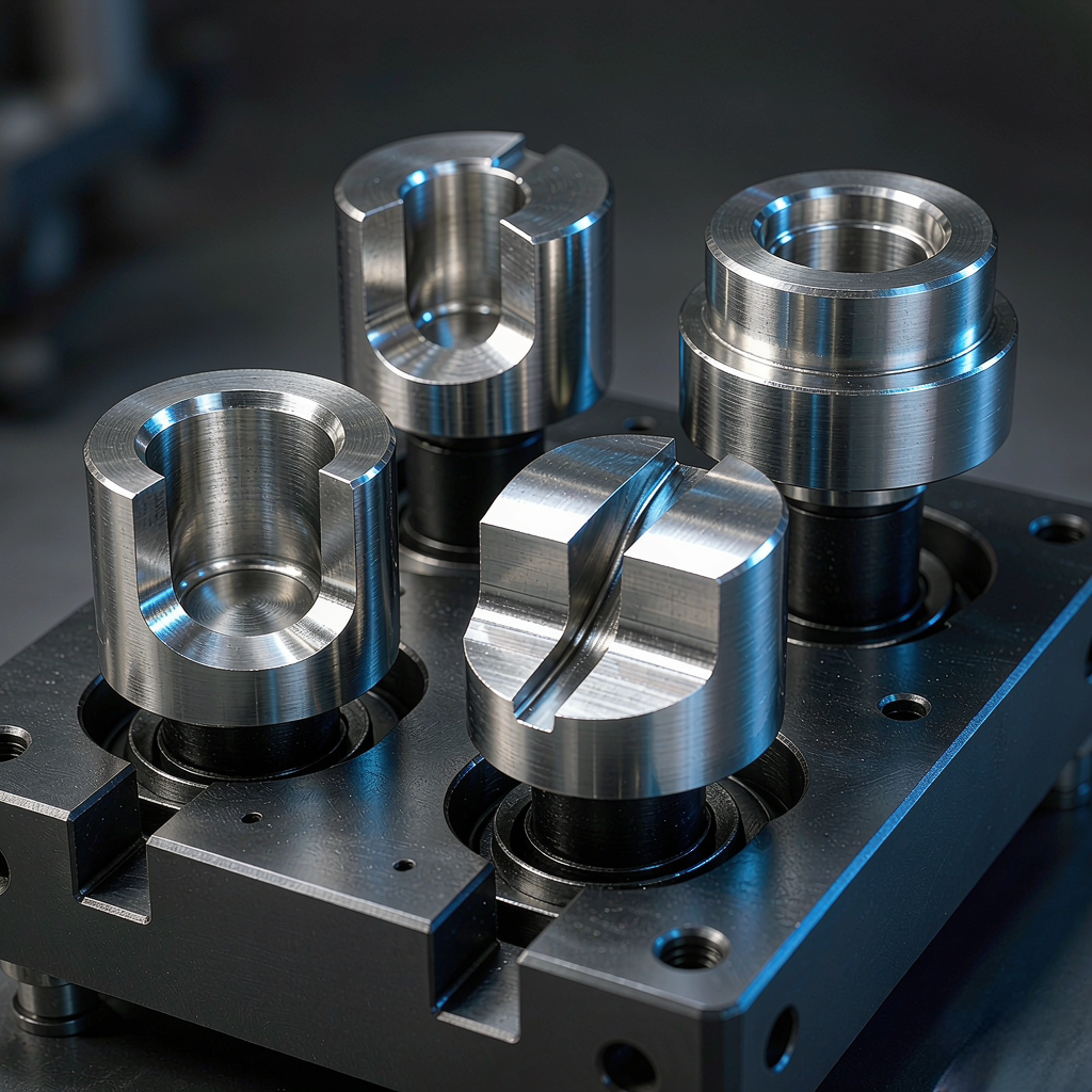
Undercuts show up in a handful of recurring shapes. Knowing the type tells you immediately which tool or axis strategy applies — and which ones you can avoid with a small design change.
Reach around the wall
A pocket whose mouth is narrower than its body. Solved with a lollipop/undercut mill, or by tilting the part so a normal end mill clears the lip.
Groove in a bore
A circumferential or axial groove inside a blind or through hole. Reachable with a grooving/undercut mill sized to the bore neck.
Trapezoidal section
A slot wider at the base than the mouth. Cut with a dovetail cutter fed straight in, no extra axes required.
Relief behind a flange
A groove behind a raised face or flange. Often needs the part rotated so the cutter meets the relief from its open side.
Behind the datum
A feature on the far side of the part. Reached by flipping, by a right-angle head, or by a rotary table that presents the back face.
Following a curve
A continuously varying undercut on a contoured surface — the one case that genuinely needs simultaneous 5-axis swarf or flow milling.
For the broader capability these features sit inside, see our 5-axis CNC machining services and our general CNC machining overview.
How 5-axis actually helps
A 5-axis machine adds two rotary axes, which means the tool or the part can be oriented in space. For undercuts that translates into two practical moves: tilt the tool so it enters at an angle that clears the lip, or rotate the part on a trunnion table so the trapped feature faces the spindle.
Neither move is "better machining" by itself — both simply change the line of sight between cutter and feature. The engineering is in deciding how little reorientation you actually need:
Rotating the part 30° may expose the undercut with a standard end mill — no special tool, no simultaneous motion.
A tilted but indexed setup stays more rigid than a fully simultaneous one, so it often holds tolerance better and runs faster.
Choosing the process: 3-axis vs 3+2 vs simultaneous
The right process is the one that reaches the feature with the least cost and risk. We rank options from simplest to most capable and stop at the first one that works.
| Approach | Best for | Trade-off |
|---|---|---|
| 3-axis + dedicated tool | Side grooves, dovetails, internal ring grooves reachable along one axis | Limited to features whose neck fits the cutter shank |
| 3+2 positional | Undercuts at a known fixed tilt or on a rotated face | Rigid and fast; cannot follow continuously curving surfaces |
| Simultaneous 5-axis | Sculpted undercuts, swarf milling, variable-angle surfaces | Most flexible; needs careful collision control and is slower per feature |
| EDM (wire / sinker) | Sharp internal corners or features no cutter can reach | Added process step and surface finish change; used only when milling cannot |
If a feature can be reached by a 3-axis tool, we keep it there. The 5-axis machine is the fallback for access, not the starting point — which is also why a custom 5-axis program is scoped feature by feature, not part by part.
Specialized tooling for undercuts
Before adding axes, we look at whether a shaped cutter already solves the geometry. The right tool often removes the need for 5-axis entirely.
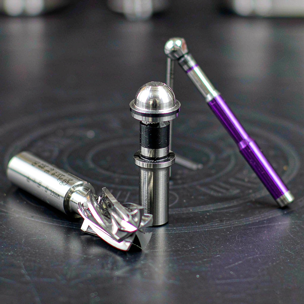
| Tool | Undercut it suits | Design note |
|---|---|---|
| Lollipop / undercut mill | Side cavities, internal relief grooves | Flutes wrap the bottom; needs clearance for the ball behind the cut |
| Dovetail cutter | Trapezoidal dovetail slots | Fed straight in along the slot axis |
| Long-reach / reduced-shank end mill | Deep, narrow cavities | Thin shank risks deflection — keep depth and stepover modest |
| Right-angle / back-spotting head | Reverse-side and back-face features | Avoids a flip or a second setup when access allows |
Tool-axis control & collision
On a tilted or rotated setup the danger is not the flutes — it is the shank and holder striking the part, the fixture or the table. Tool-axis control is how we keep the whole assembly clear.
Three numbers decide whether an undercut is safely reachable:
Tilt angle
The smallest rotation that lines the cutter up with the cut — kept minimal to preserve rigidity.
Tool length
Shortest stick-out that still reaches, because length drives deflection and collision risk.
Shank clearance
Gap between shank/holder and the wall across the entire path, not just at the cut point.
Where the holder still cannot clear, we shorten the tool, change the tilt, or split the feature across two setups. The goal is always the simplest motion that reaches the volume.
CAM & collision simulation
Undercut tool paths are where a small clearance error becomes a broken tool or a scrapped part. We simulate the full path — flutes, shank, holder, stock, fixture and table — before any metal is cut.
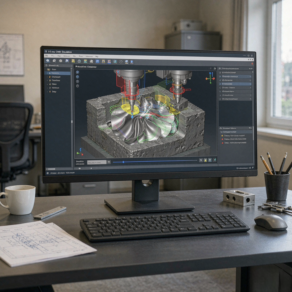
- Gouge check: the flutes stay on the intended surface, never digging past it.
- Shank and holder check: the non-cutting body clears the wall, boss and fixture everywhere it travels.
- Machine envelope: rotary limits and table travel are respected so the move is physically possible.
- First-article confirmation: simulation is a plan, not proof — the first part is still measured.
Workholding for undercut parts
A fixture that holds the part is also an obstacle the tool must avoid. For undercut work the fixture is designed around the tool path, not just around the part.
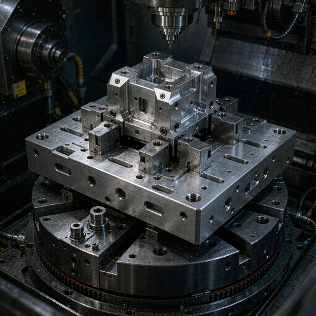
- Locate on features that will not be cut: datum faces and bores that stay clear of the undercut zone.
- Keep the fixture low and narrow: less to collide with as the part rotates.
- Plan the rotation: confirm every required angle is reachable without the clamp hitting the spindle.
DFM guidance for undercut features
Small changes at the drawing stage often remove the need for exotic tooling or extra axes. These are the adjustments we flag most often.
Widen the mouth
A slightly wider opening can admit a standard long-reach mill instead of a custom lollipop.
Avoid sharp internal edges
A small fillet lets a round cutter reach the bottom of a groove without a second operation.
Depth vs width ratio
Very deep, very narrow undercuts need long tools that deflect; shallow grooves hold tolerance better.
Split if needed
An undercut that blocks everything else can sometimes move to a second setup or a sub-component.
Inspection & verification
An undercut you cannot measure is an undercut you cannot certify. Inspection planning starts with the question: can a probe or gauge actually reach the feature?
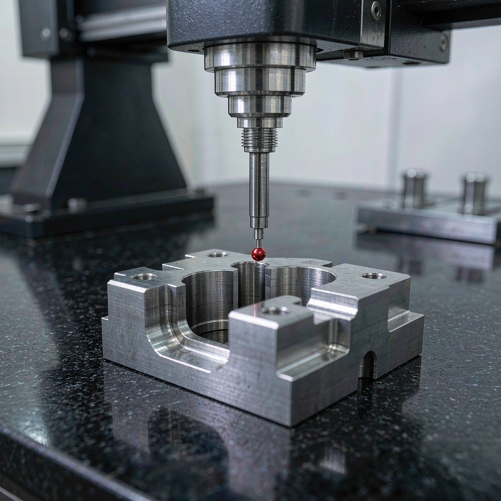
- Probe access: we confirm a stylus can reach the undercut, or call out a custom fixture/gauge.
- Per-feature tolerance: undercut dimensions are reported against the drawing, not a blanket number.
- FAI and reports: first-article inspection and dimensional reports available on request under ISO 9001:2015.
- Traceability: material certs and process records kept with the order.
For our tightest work, see precision CNC machining and the measurement approach behind it.
Case examples
Three representative part types show how the access decision is made. These are summarized as project types without disclosing customer identities.
Aluminum housing, side pocket
- ChallengeGroove behind a wall
- Approach3+2 tilt + end mill
- ResultNo custom tool needed
A side pocket sat behind a 4 mm lip. Rather than a lollipop mill, we tilted the part 22° on a trunnion table and reached the groove with a standard end mill — stiffer and cheaper than a shaped cutter.
Stainless boss, annular relief
- ChallengeGroove behind a flange
- ApproachRotate to open face
- ResultSingle setup held
An annular relief behind a raised flange was unreachable from the front. Indexing the part presented the relief to the spindle, so the groove was finished in the same setup used for the surrounding faces.
Titanium contoured undercut
- ChallengeVarying-angle surface
- ApproachSimultaneous 5-axis
- ResultSwarf milling used
A continuously curving undercut on a titanium bracket could only be followed with simultaneous 5-axis swarf milling. Collision simulation set the tool length and tilt before the first cut; first article was CMM-verified.
Request an undercut machining quote
Send the drawing and we will tell you — feature by feature — whether it is a 3-axis tool job, a 3+2, or a simultaneous 5-axis cut, and why. No blanket "5-axis for everything" assumption.
Request a QuoteXiamen Goldcattle Plastic & Metal Products Co., Ltd. · Founded in 1998 · Quoted to your drawing, feature by feature.
Frequently asked questions
What is an undercut in CNC machining?
An undercut is a feature whose cross-section is wider or offset behind a narrower opening — for example a groove inside a blind hole, a side pocket, or a dovetail slot. A straight cutting tool cannot enter the opening and then cut sideways into the trapped volume on a conventional 3-axis path, which is what makes undercuts distinct from simple pockets.
Can a 3-axis CNC machine make undercuts?
Sometimes. A 3-axis machine can produce many undercuts if the geometry is reachable with a specialized tool such as a lollipop (undercut) mill, a dovetail cutter, or a long-reach tool fed in along the access direction. The limitation is purely geometric access and tool clearance, not the axis count — we evaluate each feature before assuming 5-axis is needed.
When do you use 5-axis machining for undercuts instead of 3-axis?
We move to 5-axis when tool access cannot be solved by tool choice alone: when the undercut sits at an angle, on a rotated face, or behind a wall that blocks a straight approach. Tilting the tool or rotating the part on a trunnion table opens access without a custom tool. The decision is driven by the feature's geometry and total cost, not by a default 'use 5-axis' rule.
What specialized tools are used for undercut features?
Common choices are lollipop or undercut mills for side grooves, dovetail cutters for trapezoidal slots, long-reach and reduced-shank carbide end mills for deep narrow cavities, and right-angle or back-spotting heads for reverse-side features. Tool selection depends on the groove width, depth and the clearance the part allows.
What is the difference between 3+2 and simultaneous 5-axis for undercuts?
3+2 (positional) indexes the part at a fixed tilted angle for each operation — faster, more rigid, and sufficient when the undercut is accessible from a known orientation. Simultaneous 5-axis moves all axes together, used for sculpted or continuously varying surfaces and swarf milling where the tool angle must follow the geometry. Many undercut jobs only need 3+2.
How do you avoid collisions when machining undercuts on a 5-axis machine?
We model the tool, holder and part in CAM and run collision simulation before cutting, checking the cutting flutes, the tool shank, and the holder against the stock, fixture and table across the full tool path. Critical undercut features get their tilt angle and tool length set so the shank clears the wall. First parts are verified, not assumed.
What tolerances can you hold on undercut features?
Tolerances are held per feature against your drawing. Our typical CNC capability is around ±0.01 mm, with tighter ±0.005 mm on qualified features where the geometry and measurement support it. An undercut feature is quoted against the drawing rather than to a single blanket number, because access and measurement differ by feature.
Which materials can you machine with undercut features?
We machine undercut features in aluminum, stainless steel, titanium, brass, engineering plastics and other CNC-grade materials per your specification. Material choice affects tooling and vibration, but undercuts are a geometry problem first — we confirm grade and stock form at quotation.
What information should I send for an undercut machining quote?
Send the 2D/3D drawing (PDF/DWG plus STEP/IGES) with the tolerance block and any GD&T, the material grade, the undercut locations called out, and the quantity. Where a feature currently cannot be reached, note it — we will propose a process (special tool, 3+2, or simultaneous 5-axis) and confirm feasibility before quoting.
What is your minimum order quantity for 5-axis undercut parts?
We support prototypes from 1 piece and scale to production, so you can validate an undercut feature before committing to a run. MOQ is 1 piece for sampling; production quantities are quoted per part and process.
Ready to scope your undercut part?
Send the drawing with the undercut features marked, and we will return a process plan — 3-axis tool, 3+2, or simultaneous 5-axis — with the reason for each choice and the tolerance we can hold.
Discuss Your Part Explore our 5-axis CNC machining services