Custom Prototype Sheet Metal Stamping
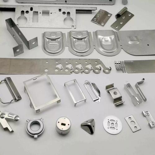
Rapid prototype and low-volume stamped metal parts manufactured to your CAD drawings and specifications — brackets, mounting plates, EMI shields, formed enclosures, clips and reinforcement components for design validation, functional testing and pre-production runs.
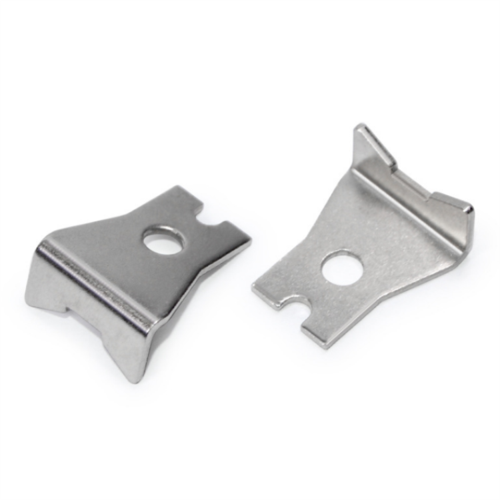
Flat sheet → formed / stamped part · the full transformation in one part
What You Need to Know Before You Request a Quote
Five answers that decide whether a stamped part is a fit for your project, and what we need from your RFQ to price it accurately.
Scope reminder: every parameter above reflects equipment and processes we run in-house. Capabilities we do not operate are stated up front rather than quoted — for example, we do not list tolerances tighter than our dies, materials we do not stock or surface finishes we do not actually apply.
Custom Prototype Stamped Metal Parts
Five application families. Send your drawing, send your material, and we will quote a stamped part to your specification.
Automotive
Electronics
Industrial Equipment
Electrical
Consumer Products
One supplier from prototype to production. Because we run stamping, CNC machining, injection molding and die casting in the same facility, a stamped prototype bracket can be tooled up, machined, or replaced by a die cast version on the same project — without sourcing from three different suppliers.
When Should You Use Prototype Sheet Metal Stamping?
The honest comparison — prototype stamping is not always the best answer. Here is how it stacks up against the alternatives we offer.
| Requirement | Prototype Stamping | CNC Machining | Laser Cutting & Bending | Production Stamping |
|---|---|---|---|---|
| Prototype Quantity | Best Fit10 – 500 pcs | Best Fit1 – 50 pcs | Good1 – 100 pcs | Poor≥10,000 pcs |
| Complex Formed Shapes | GoodBends, ribs, drawn features | AcceptableLimited by tool access | Good2D forms + bends | Best FitAny drawable geometry |
| Tooling Investment | Low – MediumPrototype die possible | LowNo tooling, fixtures only | LowNo tooling | HighProduction die required |
| Repeated Production | AcceptableTooled to repeat, with cost per hit | AcceptableCycle time limited | AcceptableCycle time limited | Best FitEngineered for volume |
| Speed for Design Iterations | GoodPrototype die is fast | GoodProgram + fixture only | Best FitSame-day possible | PoorEach die change is costly |
| High-Volume Unit Cost | GoodReasonable up to ~5k pcs | PoorCycle time dominates | AcceptableCutting + bending dominates | Best FitLowest cost at scale |
How to read this table. Ratings reflect our own production strategy, not industry-standard benchmarks. Two parts that score the same row may still be a better fit for one process than the other — geometry, material and annual volume decide the final answer. Send your drawing and we will tell you which route is the honest one.
Prototype Stamping for Design Validation
Prototype stamping is the manufacturing method you choose before committing to high-volume production tooling. It uses a lower-cost prototype die to confirm that the part can be formed, that it fits the assembly, and that the geometry is stable — so the production die, when it is built, is built once.
What you are validating with a prototype stamping run:
- Part geometry — the part can actually be formed from the chosen material at the chosen thickness.
- Mounting, fit and clearance — the part sits correctly with mating components.
- Forming behaviour — bend radius, draw depth, springback and burr direction behave as predicted.
- Assembly — the part can be installed using the intended fastening or joining method.
- Appearance — surface finish and grain direction match the specification.
Prototype Tooling Options
Three tooling routes, each matched to a stage of your programme. The right choice at the prototype stage keeps the production-tooling decision for the moment you actually need it.
Prototype Die
Short-run die built from aluminium or soft tool steel, intended for tens to a few hundred parts. Used to validate geometry, forming behaviour and assembly fit.
Use when: early-stage development, low-volume validation, design still evolving.Soft Tooling
Low-hardness tool steel die with reduced features and simplified construction. Lower initial investment than production tooling, with reasonable part consistency.
Use when: bridge production between prototype and full production tooling, or where tooling cost matters more than per-part cycle time.Production Tooling
Hardened tool steel die, full feature set, engineered for cycle time and die life. Built once the geometry is frozen.
Use when: high-volume stable production, geometry frozen, repeat order book.From CAD to Mass Production
Tooling is not a one-time decision. The loop between prototype stamping and inspection is where most prototype programmes either save or waste their tooling budget. We tell you up front which iterations we expect, rather than after the die has been cut.
Materials for Prototype Sheet Metal Stamping
Six material families we commonly stamp. Common grades per family below — other grades supplied on request. Not every alloy is suited to the same stamping operation, so material choice is part of the DFM review, not an afterthought.
| Material Family | Typical Advantages | Typical Applications | Common Grades |
|---|---|---|---|
| Carbon Steel | Strength, cost effectiveness, weldability | Brackets, structural parts, mounting plates | SPCC, SPCD, DC01, DC04, Q235 |
| Stainless Steel | Corrosion resistance, strength, surface finish | Medical, industrial, electronics, food-grade | 304, 316 / 316L, 430, 201 |
| Aluminium | Lightweight, corrosion resistance, formability | Automotive, aerospace, electronics enclosures | 5052, 6061, 1100, 3003 |
| Brass | Electrical conductivity, appearance, machinability | Electrical components, decorative parts | C26000 (cartridge brass), C27000 |
| Copper | Electrical and thermal conductivity, formability | Electrical components, busbars, heat sinks | C11000 (ETP), C12200 (DHP) |
| Spring Steel | Elastic recovery, fatigue resistance | Clips, springs, snap features | SK5, 65Mn, SUS301 (spring temper) |
Why this table is not full of "minimum tensile strength" numbers: the old page listed "stainless steel ≥500 MPa, aluminium ≥200 MPa" and similar single-line claims. Those numbers are not wrong, but they hide the fact that stainless steel is not a single material — 304 and 316L have different mechanical properties, and cold-rolled temper shifts both strength and formability. We list the grade, and we will quote against the specific grade on your drawing or your callout.
Stamping + Secondary Operations
A stamped part almost never arrives the finished part. We run the secondary operations in-house so the part you receive is ready to assemble, not a part you have to send to three more shops.
Laser Cutting
Profile and blank cutting for prototypes and short runs, including profiles that fall outside the stamping die envelope.
CNC Bending
Precision bending to drawing angle and flange height, with bend deduction controlled per material and thickness.
Deburring
Mechanical and hand deburring to remove stamping burrs on cut and pierced edges.
Tapping
Threaded holes for fasteners, either pre-tapped on the die or post-tapped after stamping.
Riveting
Self-pierce and solid riveting for sub-assemblies, on dedicated stations.
Welding
Spot, projection and MIG/TIG welding for sub-assemblies that require joining.
Grinding
Surface and edge grinding where the part requires a flat reference or a controlled burr height.
Surface Finishing
Powder coating, plating, anodising, painting and passivation — applied through our finishing network and managed to your specification.
Assembly
Light assembly of sub-components (inserts, fasteners, gaskets) so the part ships ready for your line.
Prototype Sheet Metal Stamping DFM
Ten guidelines we apply at DFM review. They are not universal numbers — they are the rules we start from before we look at your specific geometry, material and tooling strategy.
Material Thickness
Common prototype range: 0.5 – 6.0 mm. Thinner gauges form more easily; thicker gauges need higher tonnage and larger bend radii.
Confirm at quotation for the draw depth and tool access.Bend Radius
Inner radius should be at least the material thickness; smaller risks cracking on the outer fibre, particularly on harder tempers.
Inner radius ≥ material thickness as a starting point.Hole Diameter
Small pierces wear the punch faster and raise burr. Below the recommended minimum, laser cut or post-pierce is the honest answer.
Hole ≥ material thickness for normal piercing.Hole-to-Edge Distance
Too close to the edge and the part deforms or tears during forming; too far and material is wasted.
Distance ≥ 1.5 × material thickness as a starting point.Bend-to-Hole Distance
Holes placed too close to a bend deform with the bend. This is a frequent prototype failure that does not show up until assembly.
Hole edge ≥ 2 × material thickness + bend radius from the bend tangent.Flange Height
Short flanges are hard to form accurately; long flanges need draft and may wrinkle without a bead or emboss.
Flange ≥ 4 × material thickness + bend radius.Draft & Forming
Drawn features need draft to release from the punch without scoring. Without draft, parts stick and surfaces mark.
Draft ≥ 1° per side on walls deeper than 2 × diameter.Deep Drawing
Single-draw depth is limited. Beyond the limit, parts require multiple draws or annealing between operations — both add cost.
Single draw depth ≤ 0.7 × blank diameter as a starting point.Springback
All metals spring back when the load is released; harder tempers spring back more. The die angle is set to compensate.
Springback is material- and thickness-dependent — set in tooling, not corrected later.Burr & Grain Direction
Burr height and orientation matter for parts that mate, that get painted, or that feed downstream automation.
Specify burr direction on the drawing where it matters.These are starting rules, not a substitute for a DFM review. Every order receives a free DFM review — geometry, material, thickness and tooling strategy — before the die is cut. If a feature will not survive, you hear about it at that stage, not at delivery.
Quality Control for Prototype Stamped Parts
Prototype parts need a different inspection mindset from production parts — you are validating the design, not just shipping the quantity.
| Inspection Stage | What We Check |
|---|---|
| Material Verification | Material grade and lot recorded against the job; certificate available on request. |
| First Article Inspection (FAI) | First part from a new die or tool measured against the drawing call-outs. |
| Dimensional Inspection | Callipers, height gauges and pin gauges against drawing dimensions; CMM where the feature requires it. |
| Forming & Bend Inspection | Bend angle, flange height, hole-to-bend distance and bend radius against the drawing. |
| Surface Inspection | Scratches, dents, burr height, surface treatment coverage where applicable. |
| Final Pre-Packing Inspection | Quantity, labelling, packaging condition before the part leaves the floor. |
Inspection scope is agreed with you at quotation. We do not state "100% inspected" on a part unless the order actually specifies it and the inspection plan supports it. If you need a defined AQL, an FAI report or feature-level measurement reports, ask for it in the RFQ and it will be quoted as a line item.
Prototype Parts for Fit, Form & Function Validation
A stamped prototype is a measurement instrument. Three questions decide whether the part has earned its place in your design freeze.
Fit
Does the part install correctly against its mating components, with the right clearance and the right fastening interface?
- Mounting holes align
- Bend angles match mating face
- Flange heights sit flush
- Clearances match your drawing
Form
Does the part look and feel like the part you intend to ship — geometry, finish and appearance?
- Overall geometry matches CAD
- Burr direction and height acceptable
- Surface finish meets specification
- Colour / coating reads consistently
Function
Does the part do what it is supposed to do in the assembly, in service, and under expected load?
- Snap / clip engagement survives
- EMI shield covers the protected area
- Bracket carries the expected load
- Fastening torque holds without deformation
Prototype Stamping Case Study
A representative project profile for a low‑‑volume stamped bracket used in a development programme.
- Part
- Mounting bracket
- Material
- Stainless steel (304)
- Process
- Progressive die stamping · CNC bending · deburring · passivation
- Quantity
- Prototype set + low-volume batch
- Surface
- Passivated, finish as-formed
Requirement
The bracket had to mount an electronics module to a vehicle subframe, locate the connector port with consistent orientation, and survive repeated assembly cycles without cracking or permanent deformation. The geometry was still evolving between design reviews, so the tooling had to be re-cuttable.
What We Did
Material was held at 304 stainless in 1.5 mm thickness. A prototype die was cut to produce the bracket in lot sizes suitable for development vehicles. Bends were formed in-die where possible; final angle was verified on the first five parts before the rest of the run. Surfaces were deburred and passivated.
Result
Fit was verified against the customer's mating subframe before committing to the production die. Two design revisions were absorbed by the prototype die before the geometry was frozen. The low-volume batch was delivered with the inspection scope agreed at quotation, including a sample FAI report. Once geometry was final, the project moved to hardened production tooling on the same project team.
On numbers: the profile above describes the shape of this type of project, not a specific customer's data. We do not publish customer names or programme-specific figures. Your quantities, tolerances, lead times and inspection scope are confirmed in writing with your quotation and first-article report.
From Prototype to Production, on the Same Project Team
Most buyers do not actually need ten prototypes — they need a supplier that can carry the project from the first fit check to the production run. Here is what that looks like.
No re-quoting from scratch at each stage. Because we run stamping, CNC machining, injection molding, die casting and mold making in the same facility, your prototype stamping project can move to tooling, machining or a different forming process on the same engineering team — with the inspection scope, material grade and surface treatment already agreed.
Why Buyers Use Goldcattle for Prototype Sheet Metal Stamping
Founded in 1998 · 100+ machines across our six core processes.
One-Stop Manufacturing
Sheet metal stamping sits alongside CNC machining, injection molding, mold making, die casting and 3D printing in one facility under one ISO 9001:2015 quality system. All six core processes are performed in-house.
Prototype to Production
The same team that cuts your prototype die cuts your production die when geometry is ready. No re-sourcing at the point where the programme risk is highest.
Three Tooling Routes
Prototype die, soft tooling and production tooling — the route you need is matched to your programme stage, not pushed toward the most expensive option.
Engineering Support
Free DFM review on every order: bend radius, hole position, flange height, draft, burr direction. The trade-off is in writing before the die is cut.
Honest about scope. Capabilities outside the six processes we run in-house are stated up front, not after the order is placed. If your programme needs a capability we do not have, we will say so rather than quote for it.
What We Need for a Prototype Stamping Quote
Six items in your RFQ are enough to price a prototype stamping job accurately. More is fine, less usually means we will have to come back with questions.
- 3D CAD — STEP / STP / IGES preferred. Native SolidWorks and CATIA files accepted.
- 2D drawing — dimensions, GD&T, tolerances, surface finish call-outs.
- Material — material grade and temper. If you have not chosen yet, send the application and we will advise.
- Quantity — prototype quantity plus estimated production volume if known.
- Surface finish — plating, coating, anodising, passivation, paint or as-formed.
- Application — automotive / electronics / industrial / electrical / consumer.
Questions Buyers Ask Before Ordering
What is prototype sheet metal stamping?
Prototype stamping uses a short-run die to produce tens to a few hundred metal parts before committing to the high-volume production die. It lets you validate geometry, fit, forming behaviour and assembly before the production tooling is cut — which is where most tooling budgets are either won or wasted.
Can you manufacture one or a few stamped prototypes?
Yes — a single prototype is a valid order. For one or two parts, laser cutting and CNC bending may actually be cheaper than cutting a die. We will tell you which route is the honest one for your geometry.
Do prototype stamped parts require production tooling?
Not necessarily. For tens of parts a prototype die is enough. For one or two, laser + bend usually is. For thousands, production tooling pays back. We will quote each route so you can see the crossover.
What metals can you stamp?
Carbon steel, stainless steel (304 / 316L / 430), aluminium (5052 / 6061 / 1100 / 3003), brass, copper and spring steel. Specific alloys outside this list are supplied on request — tell us the grade and we will confirm.
Can you manufacture parts from my CAD drawing?
Yes. Send a STEP, STP or IGES file plus a 2D drawing with tolerances and material. We run a DFM review before the die is cut and tell you which features need adjustment.
Can prototype stamping support complex bends and formed features?
Yes, within material and tooling limits. Bends, ribs, drawn features and embosses are routine prototype-stamp features. Deep draws above 0.7 × blank diameter usually require multiple draws or annealing between operations — we will tell you up front.
Can you provide surface finishing?
Yes — powder coating, plating, anodising, painting and passivation are available through our finishing network and managed to your specification. Specify the finish on the drawing so it can be quoted as a defined step.
Can prototype parts later move to mass production?
Yes — that is the main reason to choose a one-stop supplier for prototypes. The same team cuts the production die when geometry is frozen, with the material, finish and inspection scope already agreed.
What affects prototype stamping cost?
Five drivers — material grade and thickness, part complexity, tooling choice (laser + bend / prototype die / soft tooling), quantity, and surface finish. We will quote each line separately so you can see where the cost actually sits.
How long does prototype stamping take?
Tooling cut typically takes 7–15 business days for a prototype die, depending on complexity. First articles are inspected and approved before the rest of the lot is run. Lead time is quoted against the actual tooling route you choose.
Ready to Prototype Your Stamped Metal Part?
Send the CAD and the 2D drawing with material, finish and quantity. You will get a DFM review, a tooling recommendation and a quote with each cost line itemised — no bundled assumptions.
Other Services in This Manufacturing Cluster
Plain-text mentions, not links, until the underlying pages exist: automotive parts (page pending), sheet metal fabrication as a standalone page (pending — the live parent is sheet-metal-fabrication-services), stamping dies as a standalone page (pending — the live parent is metal-stamping-dies), and rapid prototyping (404 at the time of this rebuild).