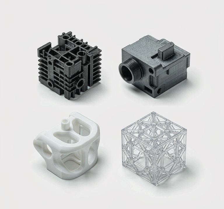
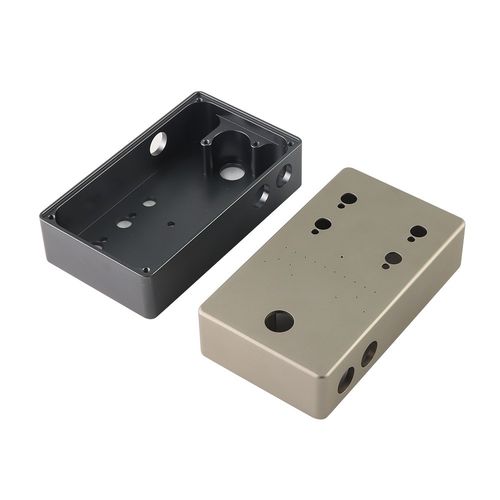
5-Axis CNC Machining Engineering Guide
3+2 vs. simultaneous 5-axis machining, workholding, toolpath strategy, surface finish, tolerances, inspection and cost considerations for complex precision parts.
5-axis machining is most valuable when part geometry, feature access or datum relationships make multiple 3-axis setups costly or difficult to control. But "5-axis" alone does not define the manufacturing result. The actual outcome depends on whether the process uses 3+2 positioning or simultaneous 5-axis motion, how the workpiece is referenced, how toolpaths are simulated, how rotary axes are controlled, and how the finished part is inspected.
What 5-Axis Actually Changes
Adding two rotary axes to a 3-axis mill does not automatically produce better parts. It changes what the machine can access, how the workpiece is oriented, and how features relate to each other through a shared datum.
Multi-Face Access
- Machining angled holes, pockets and surfaces without re-fixturing
- Access to features on opposite or oblique faces from one setup
- Reduced manual repositioning and datum transfer operations
Tool Orientation Control
- Tilt the cutter to reach undercuts and deep cavities
- Use shorter, more rigid tools by reorienting the workpiece
- Maintain favorable cutting conditions on complex surfaces
The value of 5-axis is not "more axes = more precision." It is geometry-dependent access and orientation control that reduces re-fixturing risk and improves feature-to-feature relationships — but only when the process is engineered correctly.
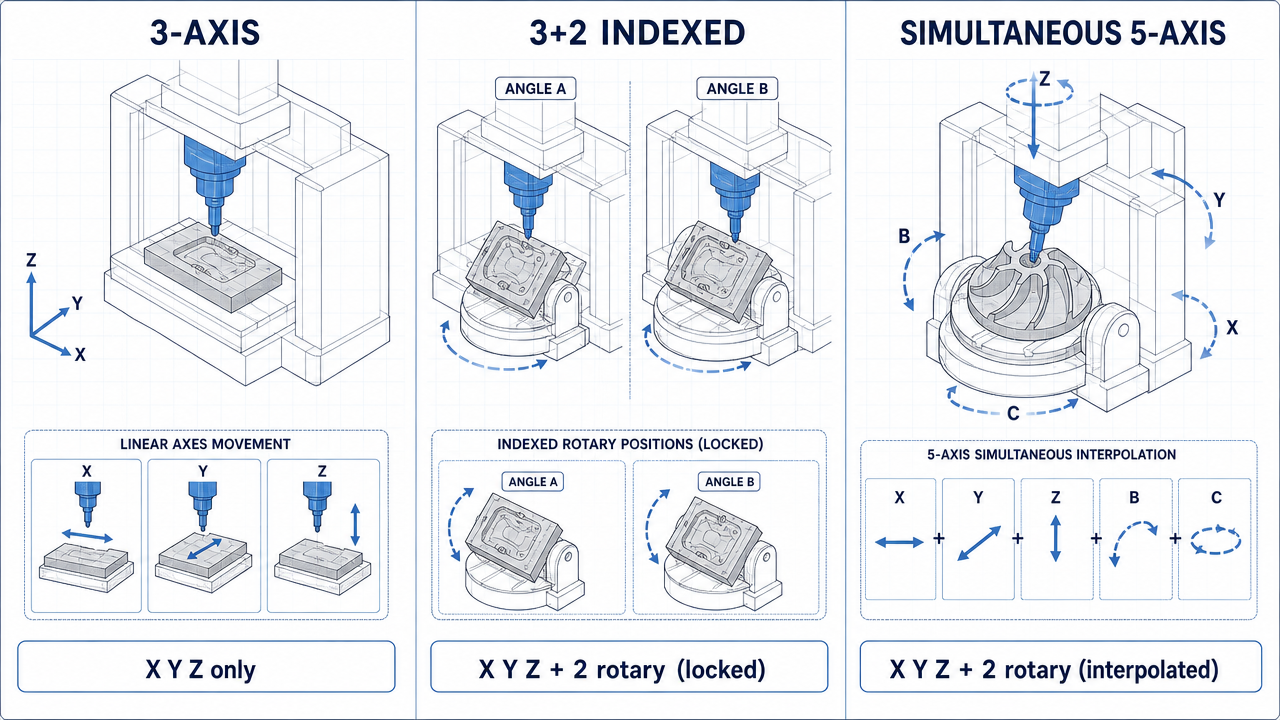
3+2 vs. Simultaneous 5-Axis Machining
This distinction is the single most important concept on this page. A 5-axis machine can be used in three different ways — and the choice determines programming complexity, cycle time, surface quality and cost.
| Factor | 3+2 Indexed | Simultaneous 5-Axis |
|---|---|---|
| Rotary axes during cutting | Locked at selected orientation | Continuously interpolated |
| Typical geometry | Angled holes, multi-face parts | Compound curves, blades, impellers |
| Programming complexity | Lower | Higher |
| Tool orientation | Fixed during each operation | Continuously changes |
| Surface finishing | Good for many indexed surfaces | Strong for complex freeform surfaces |
| Collision management | Simpler | More demanding |
| CAM requirement | Moderate | High |
| Typical setup reduction | Significant vs. many 3-axis setups | Potentially significant |
| Best use | Prismatic / multi-face parts | Complex continuous surfaces |
5-Axis Does Not Always Mean Simultaneous 5-Axis. A 5-axis machine can run 3+2 positioning, simultaneous 5-axis toolpaths, or even ordinary 3-axis operations. When a supplier says "we have 5-axis machines," the real question is: which mode will be used for your part, and why?
5-Axis Does Not Automatically Mean Better Accuracy
Reducing re-fixturing can simplify the relationship between features, but the benefit depends on how the part is located, supported and referenced during machining.
A machine's published positioning accuracy (e.g., ±0.001 mm) is not the same as a guarantee that every feature on every customer part will be machined to that value. Rotary-axis positioning error, thermal drift, tool deflection, fixture deformation and calibration condition all contribute to final part capability.
| Accuracy Layer | What It Means |
|---|---|
| Machine positioning accuracy | Axis positioning capability per ISO 230-2 |
| Rotary-axis accuracy | Angular positioning behavior of rotary axes |
| Machine volumetric accuracy | Combined spatial error across the working envelope |
| Process capability | What the machining process can repeatedly produce |
| Part tolerance | Drawing requirement — what the part must achieve |
| Inspection uncertainty | Measurement system limitation (CMM, probes, etc.) |
References: ISO 230-2:2014 — determination of accuracy and repeatability of numerically controlled axes; ISO 10791-7:2020 — accuracy of finished test pieces for machining centres, including 5-axis freeform test pieces.
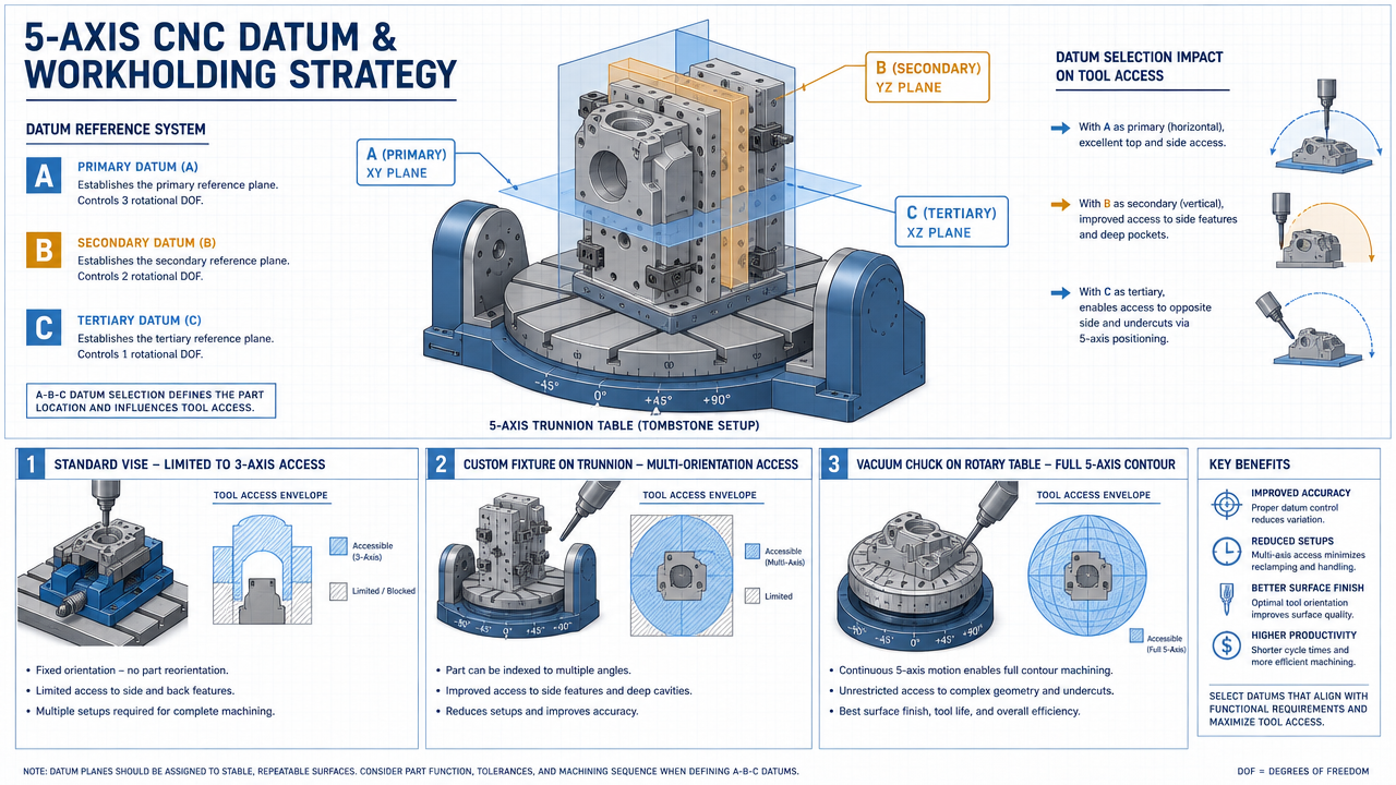
Datum & Workholding Strategy
Why datum strategy matters more than axis count. The fixture must not only hold the part — it must allow the tool to reach the workpiece from multiple orientations.
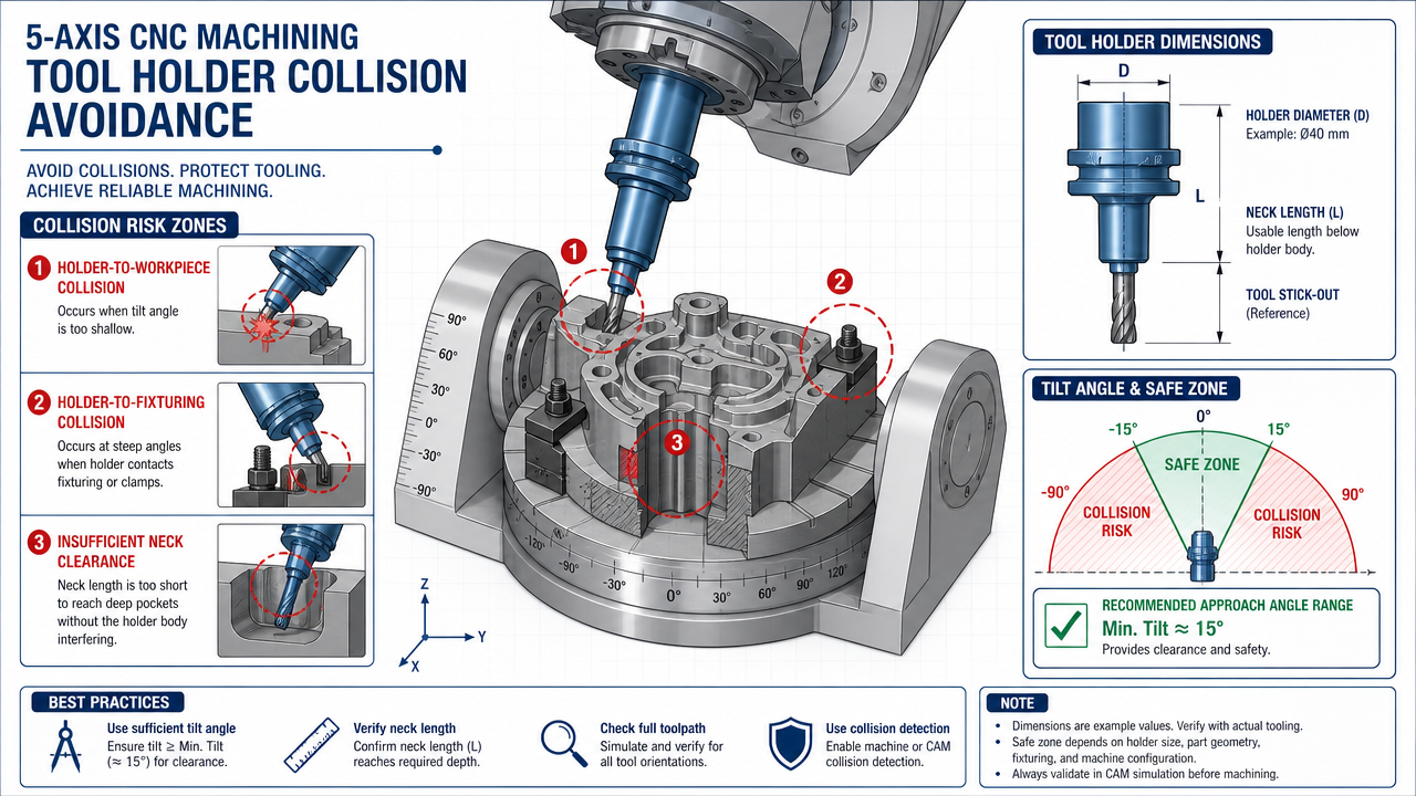
Datum Considerations
- Datum selection aligned with drawing GD&T scheme
- Datum transfer risk between setups
- Reference feature accessibility for inspection
- Part deformation under clamping forces
Fixture Requirements
- Rigidity: resist cutting forces without deflection
- Access: allow tool and holder to reach all orientations
- Clamp interference: no collision with tool paths
- Rotary-axis envelope: fit within machine travel limits
- Chip evacuation: avoid trapping coolant and chips
CAD Review
Evaluate geometry, critical datums and access requirements
Datum Identification
Map GD&T datum scheme to workholding reference features
Machine Orientation
Determine rotary-axis positions for each operation
Fixture Concept
Design workholding that provides rigidity and access
Tool Accessibility Check
Verify tool and holder reach every surface without collision
Collision Simulation
Run CAM simulation against fixture, holder and machine model
Machining
Execute programmed toolpaths with in-process monitoring
Inspection
Verify features against drawing datum scheme on CMM
5-Axis CNC Toolpath Strategy
Tool-axis control is often the difference between having a 5-axis machine and using 5-axis effectively.
Roughing
- Efficient stock removal at stable conditions
- Avoid tool overload and chatter
- 3+2 orientation often sufficient for pocket clearance
Semi-Finishing
- Control remaining stock uniformity
- Manage tool accessibility across transitions
- Prepare even allowance for finishing
Finishing
- Tool orientation relative to surface normal
- Scallop height and step-over control
- Curvature-adaptive tool engagement
Rest Machining
- Remove material left by previous larger tools
- Deep channels, corners and difficult-to-access areas
- Often requires simultaneous 5-axis tool orientation
Tool-Axis Control Methods
- Swarf machining — tool side cutting along ruled surfaces
- Morph / flow-line — toolpath follows surface curvature
- Automatic tool tilting — collision avoidance with holder
- Digital-twin simulation — verify against full machine model
Tool-axis control is often the difference between having a 5-axis machine and using 5-axis effectively. A part that requires simultaneous tool orientation changes cannot be produced correctly in 3+2 mode, regardless of machine capability.
Tool Reach & Collision Avoidance
The question is not only "will the cutter reach the surface?" but also "will the holder reach the surface without collision?"
Tool & Holder Parameters
- Tool length — longer reach, more deflection
- Tool diameter — must fit into smallest feature
- Holder diameter — limits access in tight areas
- Neck clearance — holder-to-workpiece gap
Collision Zones
- Tilt angle — minimum and maximum safe range
- Part clearance — holder vs. adjacent surfaces
- Fixture clearance — holder vs. clamps and fixture body
- Machine envelope — rotary axis travel limits
In 3+2 mode, short and rigid tools can access difficult areas because the workpiece is repositioned to present the feature at a favorable angle. In simultaneous mode, the tool orientation changes continuously, which can solve access problems but demands collision simulation against the full machine, holder and fixture model.
How Part Geometry Maps to 5-Axis Strategies
Not "what industries use 5-axis" — but which geometries require which 5-axis approach.
| Part Geometry | 5-Axis Strategy |
|---|---|
| Angled holes | 3+2 indexed |
| Multiple angled faces | 3+2 / indexed |
| Deep pockets | 3+2 / multi-orientation |
| Undercuts | Indexed or simultaneous, depending on geometry |
| Blade surfaces | Simultaneous |
| Impellers | Simultaneous |
| Blisks | Simultaneous |
| Sculptured molds | Simultaneous or indexed, depending on geometry |
| Medical freeform implants | Often simultaneous / application-dependent |
| Multi-face housing | 3+2 is often sufficient |
5-Axis Applications by Geometry
Organized by geometric challenge — not by industry label.
Freeform Surfaces
- Impellers and turbine blades
- Mold cavities and cores
- Orthopedic implant contours
Multiple Critical Faces
- Housings and manifold blocks
- Structural brackets
- Valve bodies with cross-drilled ports
Angular Relationships
- Aerospace fittings with angled bores
- Custom mechanical components
- Multi-axis mounting interfaces
Deep / Inaccessible Features
- Complex internal cavities
- Narrow blade passages
- Undercut features and back-pockets
Material-Specific 5-Axis Machining Considerations
Not generic cutting speeds — but the process challenges and focus areas that change with each material.
| Material | Main Challenge | Process Focus |
|---|---|---|
| Aluminum 6061 / 7075 | Tool loading, chatter, thin walls | Tool geometry, chip evacuation, workholding |
| Stainless steel 304 / 316L | Work hardening, heat generation | Stable engagement, coolant strategy, tool selection |
| Titanium | Heat concentration, low thermal conductivity | Tool engagement, rigidity, heat management |
| Inconel 718 | Difficult machinability, rapid tool wear | Conservative engagement, rigidity, tool wear monitoring |
| Mold steel (H13, P20) | Hardness / surface finishing requirements | Tool selection + finishing strategy |
| PEEK / engineering plastics | Low stiffness / heat sensitivity | Workholding + thermal control |
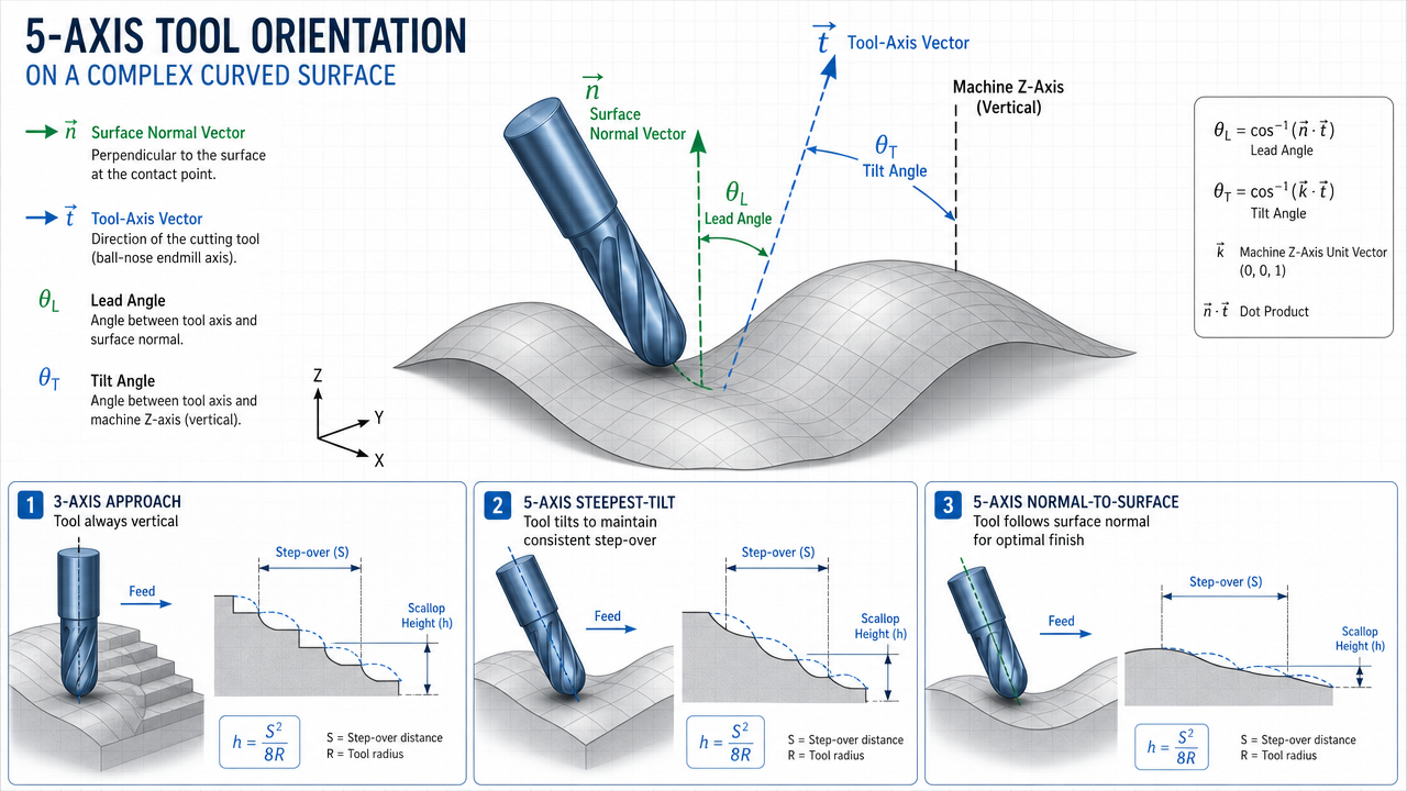
How 5-Axis Tool Orientation Affects Surface Finish
5-axis does not automatically improve surface finish. It can improve finish on complex surfaces — when the tool orientation is controlled correctly.
Factors Controlling Finish
- Tool orientation relative to surface normal
- Ball-end cutter contact point and step-over
- Scallop height control
- Surface curvature and tool engagement
- Tool deflection under cutting load
5-Axis Advantage for Finish
- Changing tool orientation can maintain favorable cutting conditions on compound surfaces
- Shorter tools (less deflection) can reach features by repositioning the workpiece
- Indexed 3+2 can produce excellent finish on flat or mildly curved faces
- Simultaneous is needed where surface normal varies continuously
3-Axis vs. 3+2 vs. Simultaneous 5-Axis: Cost Comparison
A higher 5-axis machine rate does not necessarily mean a higher total part cost. The geometry determines which process is most economical.
Cost Factor Breakdown
Cost Estimation Framework
When 3-Axis Is Actually the Better Choice
Not every part benefits from 5-axis. Choosing 5-axis for a simple part is a cost error — and a supplier that recommends the right process, not the most expensive one, earns trust.
3-Axis Is Typically Better For
- Flat brackets and plates
- Simple housings with orthogonal features
- Single-face geometry
- Simple pockets and standard holes
- High-volume simple parts where machine rate matters
5-Axis Becomes Advantageous When
- Multiple critical faces require tight positional relationships
- Angled features would otherwise require custom fixtures
- Deep or undercut features need non-standard tool access
- Complex surfaces need continuous tool orientation changes
- Reduced setups offset higher machine rate and programming cost
3-axis when it is sufficient. 3+2 when fixed orientations solve the geometry. Simultaneous 5-axis when continuous tool orientation or complex surface access justifies it. We do not select 5-axis simply because the machine is available.
3-Axis + Multiple Setups vs. 5-Axis
A procurement-oriented comparison of the real trade-offs, not a fixed percentage reduction.
Option A — 3-Axis + Multiple Setups
Option B — 5-Axis
When evaluating 3-axis vs. 5-axis, consider: setup labor, fixture cost, datum transfer risk, inspection time, lead time, and scrap / rework risk. Fewer setups do not automatically guarantee better accuracy — machine geometric error, thermal stability, tool deflection and fixture deformation still contribute.
RTCP / Tool Center Point Control: Why It Matters
In multi-axis machining, the control system must continuously coordinate linear and rotary movement so that the programmed tool center follows the intended location as the machine orientation changes.
What RTCP / TCPC Does
- Automatically compensates linear axes when rotary axes move
- Programs tool center point motion instead of individual axis positions
- Simplifies setup: tool length and fixture offsets handled by the controller
- Reduces programming errors in simultaneous 5-axis toolpaths
Why It Matters for Your Part
- Without RTCP, every rotary motion requires manual linear-axis compensation
- Setup changes (different fixture position) require reprogramming
- RTCP-enabled controllers make 5-axis more repeatable and less operator-dependent
- Ask: does the supplier use RTCP for simultaneous 5-axis operations?
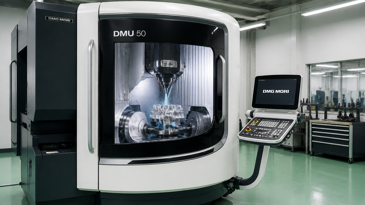
5-axis ≠ just a rotary table. RTCP/TCPC is what makes the controller behave as a true 5-axis system rather than a 3-axis mill with a positioning rotary table. Machines like the DMG MORI DMU 50 support RTCP natively for simultaneous 5-axis interpolation.
How to Qualify a 5-Axis Machine
Machine capability verification is where most 5-axis claims can be independently validated — or challenged.
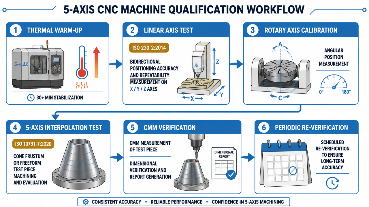
Axis Accuracy
- ISO 230-2 — linear and rotary axis positioning accuracy / repeatability
- Rotary-axis angular positioning calibration (e.g., Renishaw XR20-W)
- Axis alignment verification between linear and rotary axes
Finished Test Piece
- ISO 10791-7 — machining centre finished test piece accuracy
- Includes 5-axis freeform test piece geometry
- Verifies combined linear + rotary interpolation capability
Thermal & Environmental
- Machine warm-up procedure before critical operations
- Thermal condition monitoring during long machining cycles
- Ambient temperature control in precision machining areas
Periodic Verification
- Scheduled recalibration of axes and rotary tables
- Machine performance tracking over time
- Comparison against baseline acceptance data
5-Axis Part Inspection
From GD&T to measurement — features on different faces and orientations must be measured relative to the drawing datum scheme.
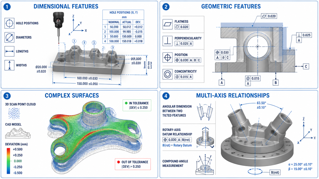
Dimensional Features
- Hole diameter and position
- Pocket dimensions and depth
- Wall thickness
Geometric Features (GD&T)
- Position, profile, flatness
- Perpendicularity, parallelism
- Runout and concentricity
Complex Surfaces
- Profile deviation against CAD model
- Surface finish measurement
- Blade and impeller geometry verification
The 5-Axis Quality Loop
Design → process → quality are not independent steps. Each stage feeds back into the next.
CAD / GD&T
Datum scheme, tolerances, critical features
→DFM Review
Manufacturability, access, fixturing
→CAM / Simulation
Toolpaths, collision check, verification
→Fixture / Datum
Workholding, reference alignment
→5-Axis Machining
Programmed toolpaths, in-process monitoring
→In-Process Verification
On-machine probing, intermediate checks
→CMM / Final Inspection
Full GD&T verification against drawing datums
→Feedback / Adjustment
Process correction, tool wear compensation
Buyer Decision Matrix: Which Process Fits Your Part?
Not "which is better" — but "which geometry needs which strategy."
| Buyer Requirement | 3-Axis | 3+2 | Simultaneous 5-Axis |
|---|---|---|---|
| Simple plate | ●●● | — | — |
| Simple housing | ●●● | ● | — |
| Angled hole | ● | ●●● | ● |
| Multiple angled faces | ● | ●●● | ●● |
| Deep access features | ● | ●● | ●●● |
| Freeform surface | — | ● | ●●● |
| Impeller / blade | — | — | ●●● |
| Tight relationship across several faces | ● | ●●● | ●●● |
| High volume simple part | ●●● | ● | — |
| Highly complex prototype | ● | ●● | ●●● |
Buyer Checklist: How to Verify a 5-Axis Supplier
What should a buyer ask before approving 5-axis production? These questions separate process-capable suppliers from machine owners.
Machine
- What machine model will run my part?
- What is the axis configuration (table-table, head-head, head-table)?
- What is the working envelope and rotary-axis range?
- Is RTCP / TCPC supported for simultaneous operations?
Process
- Is this 3+2 or simultaneous 5-axis for my geometry?
- How is the workholding designed for my part?
- What datum strategy will be used?
- Which CAM system and how is the toolpath simulated?
- How is tool-holder collision checked?
Quality
- CMM available? What type and software?
- FAI / first-article inspection included?
- Profile measurement against CAD model?
- Position, runout, surface finish verification?
- Inspection report format and datum alignment?
Machine Verification
- Rotary-axis calibration method and frequency?
- Machine acceptance / verification data available?
- Periodic recalibration schedule?
- ISO 230-2 / ISO 10791-7 compliance?
What Determines 5-Axis Lead Time
Not a fixed "3–7 days" — but the real components that make up the delivery timeline.
Engineering Review
DFM analysis, geometry evaluation, process selection
CAM Programming & Simulation
Toolpath generation, collision verification, post-processing
Fixture Preparation
Custom workholding design and manufacture if required
Material Availability
Stock check or procurement for specified material grade
Machining Time
Actual cutting time including roughing, finishing and rest machining
Heat Treatment / Finishing
Stress relief, surface treatment, anodizing, plating as required
Inspection
CMM measurement, GD&T verification, documentation
Customer Approval
FAI review, dimensional report sign-off, release to production
Case Study: 5-Axis Machining of an Inconel 718 Impeller
A real project that demonstrates simultaneous 5-axis capability — not a hypothetical scenario.
Inconel 718 Impeller — Simultaneous 5-Axis CNC Machining
248 mm diameter · 17 curved blades · DMG MORI DMU 50 · 8 business days
- Geometry 248 mm diameter, 17 curved blades, narrow blade-to-hub passages
- Material Inconel 718 — difficult machinability, rapid tool wear
- Challenge Restricted tool access between blades, complex blade-to-hub surface relationships, heat management
- Why 5-Axis Simultaneous tool orientation required for curved blade surfaces; reduced datum transfer; controlled tool approach through narrow passages
- Machine DMG MORI DMU 50 — simultaneous 5-axis with RTCP
- Inspection CMM dimensional verification, blade profile against CAD
- Outcome Machined from solid in 8 business days, full inspection documentation
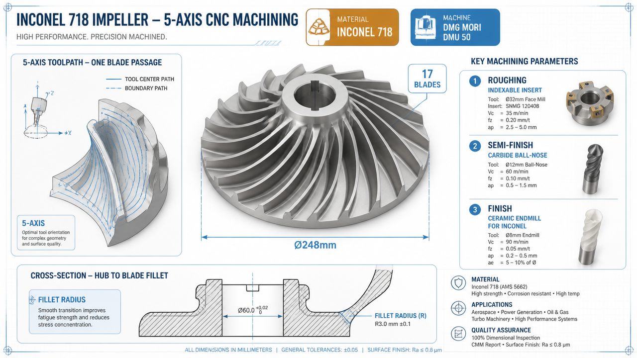
This case demonstrates simultaneous 5-axis capability on a geometry that cannot be produced in 3+2 mode — the blade surfaces require continuous tool orientation changes through the entire cutting path. See full case study at Inconel 718 Impeller 5-Axis CNC Machining.
How Goldcattle Applies 5-Axis Machining
Manufacturing since 1998. Real machines, real process decisions, real inspection — not just "we have 5-axis."
5-Axis Platforms
- DMG MORI DMU 50 — simultaneous 5-axis
- Mazak 5-axis machining centers
- 3+2 indexed and simultaneous capability
Process Options
- 3+2 indexed positioning
- Simultaneous 5-axis interpolation
- CNC milling and turning
- Grinding / secondary machining
Engineering
- DFM review and process selection
- Datum planning and fixture strategy
- CAM programming and simulation
- Collision verification before machining
Quality
- CMM inspection against drawing datums
- Dimensional verification and FAI
- Profile, position, runout measurement
- Full inspection documentation
Related 5-Axis Resources
Each page serves a different search intent — this guide covers engineering method, other pages cover services, decisions and fundamentals.
5-Axis CNC Machining Services
Commercial manufacturing, machines, quote request
When to Use 5-Axis CNC Machining
Decision guide: should you choose 5-axis?
What Is 5-Axis CNC Milling
Definition, axis configurations and fundamentals
Inconel 718 Impeller Case Study
Full project details: 248 mm, 17-blade impeller
Frequently Asked Questions
Engineering-focused answers — not "what industries use 5-axis."
Request a 5-Axis Engineering Review
Send your 2D drawing, 3D CAD model, material, quantity and critical tolerances. We can review the part geometry and determine whether 3-axis, 3+2 or simultaneous 5-axis machining is the appropriate manufacturing route.