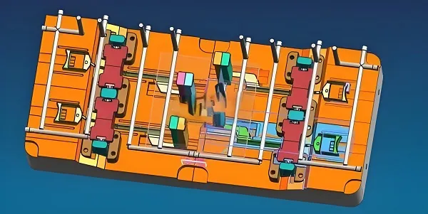
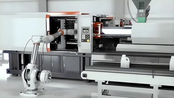
Rapidly produce transparent polycarbonate prototypes for fit, form, functional and visual validation. Choose CNC machining, rapid tooling or 3D printing based on part geometry, quantity and required optical appearance.
What Is Clear Polycarbonate Rapid Prototyping?
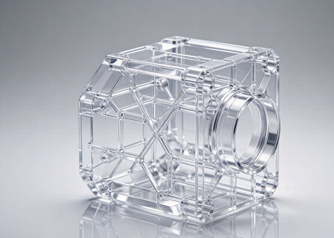
Clear polycarbonate rapid prototyping is the fast production of transparent PC prototype parts for design, assembly, functional and visual validation. Depending on part geometry, quantity and transparency requirements, prototypes may be produced by CNC machining, rapid tooling / injection molding, vacuum casting or other suitable processes. Not every clear PC part is made the same way — the right method depends on what you need to learn from the prototype.
Goldcattle operates CNC machining, injection molding and 3D printing lines in-house, so the value of this page is not only making a part — it is helping you select the correct prototype process before cutting material.
Why Use Polycarbonate for Transparent Prototypes?
Polycarbonate (PC) is chosen when a transparent part must also survive impact, heat and handling — not only when it must look clear.
Impact Resistance
PC is substantially more impact-resistant than PMMA / acrylic. For parts that may be dropped, clamped, bolted or subjected to mechanical stress, PC is usually the safer transparent choice.
Transparency
Clear PC delivers strong visible transparency. Note: PC typically reaches around 88–90% light transmission, while PMMA is generally higher. Choose PC when toughness matters more than maximum optical clarity.
Heat Resistance
PC tolerates higher service temperatures than standard acrylic, making it suitable for enclosures, lamp-adjacent parts and warm-environment validation.
Functional Prototyping
Ideal for protective covers, transparent housings, machine guards, sensor windows, fluidic components and electronic enclosures where function and visibility both matter.
Clear Does Not Always Mean Optical-Grade
Transparency is not one requirement. Defining the level early prevents over-engineering — or under-delivering.
Visual Transparency
You only need to see internal structure, routing or assembly. Surface perfection is not required.
Clear Functional Prototype
Transparent and mechanically functional — assembly, sealing faces, threaded inserts and load paths must all hold up.
Optical / Light-Path Prototype
Requires controlled surface quality, transmission, distortion control and optical geometry. Treated as a separate specification, not "just clear PC."
Not every clear PC prototype is an optical prototype. Optical requirements should be defined separately from simple visual transparency.
How Clear Can CNC-Machined Polycarbonate Be?
A machined PC part can be made transparent and polished, but the final appearance depends on the starting material, machining marks, toolpath, surface condition, polishing method, internal stress and part geometry. Avoid vendors who promise perfect clarity for every part — transparency is a result of process, not a default state.
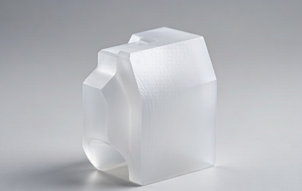
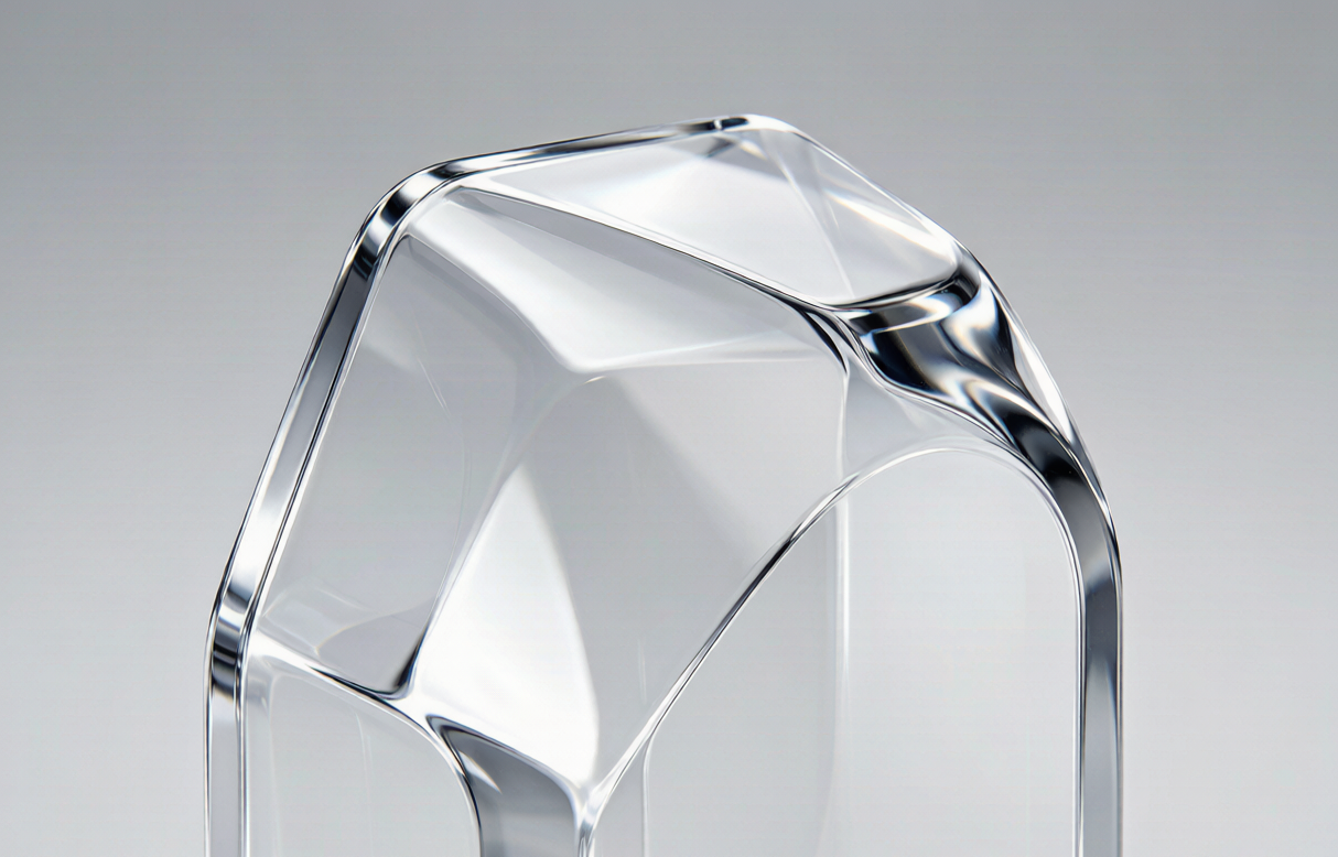
If transmission or haze is a defined acceptance criterion, the material grade and finishing route should be selected against that specification before machining begins.
What Makes Clear PC Prototyping Difficult?
The hard part of clear PC is rarely "can it be cut." It is whether the transparent region can be brought to an acceptable state without harming dimensions or surface.
Scratching
PC is softer than PMMA and picks up scratches more readily during machining, handling and finishing.
Heat Generation
Machining heat affects surface quality and can contribute to internal stress if not managed with correct speeds, feeds and tooling.
Stress Cracking
Excessive mechanical stress or aggressive post-processing can induce crazing or micro-cracks in transparent parts.
Tool Marks
On a clear part, every cutter path is far more visible than on a black or white PC component — surface strategy matters.
Handling
Fingerprints, dust and minor scratches after finishing can all degrade the transparent appearance. Protective packaging is part of the process.
Finishing Is the Real Constraint
The question is not "can we machine it," but "can we bring the clear region to the state you will accept — without hurting dimension or surface?" That is where clear PC differs from opaque plastic.
Clear Polycarbonate Prototype Manufacturing Process
A structured flow keeps transparency requirements visible from CAD review to protective packaging.
- 01 CAD review & transparency requirement capture
- 02 Clear PC grade selection (general / UV-stabilized / hard-coated)
- 03 Stock material verification (virgin grade, batch record)
- 04 CNC machining / rapid tooling per geometry
- 05 Deburring & stress-relief where applicable
- 06 Surface finishing & polishing to target clarity
- 07 Dimensional inspection (CMM / key features)
- 08 Visual & transparency inspection
- 09 Protective packaging for clear surfaces
Clear Polycarbonate Material Options
"Clear polycarbonate" is not a single material. Grade and additives change scratch resistance, UV stability and suitability.
General-Purpose Clear PC
For housings, covers, guards and functional prototypes where toughness and transparency are both needed.
Optical / Specialty PC
Optical-grade families (e.g., Sabic Lexan, Covestro Makrolon classes) are selected against a stated optical specification — not by default.
UV-Stabilized PC
Recommended for outdoor or sun-exposed parts to slow yellowing over service life.
Hard-Coated PC
Adds scratch resistance for windows, display surfaces and touch-exposed clear areas. Confirm availability per project.
Clear Polycarbonate CNC Machining
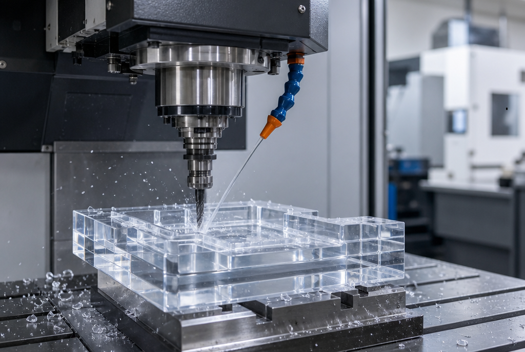
CNC machining is the most direct route for low-to-mid quantity transparent functional parts made from real polycarbonate. 3-, 4- and 5-axis capability lets us reach complex internal channels and critical faces with fewer setups — useful when a clear housing has both optical windows and sealed mounting features.
- Real PC stock — material authenticity preserved
- Good dimensional control for assembly-critical features
- Easy design iteration between prototype revisions
- No tooling required for low volumes
Clear Polycarbonate Prototype DFM Guidelines
Transparent parts expose geometry problems that opaque parts hide. Apply these early to protect both clarity and function.
Wall Thickness
Avoid sudden thickness changes — clear parts show sink, warp and stress more than opaque ones.
Internal Corners
Avoid overly small internal radii; they raise stress and complicate clean, mark-free surfaces.
Holes
Define hole size, depth and tool access so drilled features stay clean and dimensionally stable.
Threads
Threads in clear PC are common weak points for both appearance and strength — specify class and depth.
Thin Walls
Consider deflection, machining stress, transparency and handling together before specifying wall stock.
Critical Transparent Surfaces
Mark optically / visually critical surfaces on the drawing. Define allowed scratches, tool marks, haze, bubbles, polishing marks and distortion tolerance.
Clear Polycarbonate Finishing & Polishing
Finishing is selected to match the required transparency — not applied uniformly to every part.
As Machined
Fastest and lowest cost. Suitable when only internal visibility is needed.
Fine Sanding
Improves surface consistency before any polishing step.
Mechanical Polishing
Raises transparency for visual and functional prototypes via progressive abrasive polishing.
Edge / Window Polishing
Targeted on windows, housings and transparent covers where the eye lands first.
Coatings
Hard coat, anti-reflective or UV coat where the application demands it — confirm per project, not assumed.
A Note on Vapor Polishing
Some suppliers apply vapor polishing to PC, but grade, solvent system and application vary widely. We select mechanical / specialty polishing according to required transparency and surface condition rather than defaulting to one method.
How Are Clear PC Prototypes Inspected?
Visual inspection and dimensional inspection are not the same as optical inspection. We match the inspection layer to the stated requirement.
Dimensional Quality
Critical dimensions, flatness, hole size and assembly interfaces checked against the drawing.
Visual Quality
Scratches, haze, tool marks, bubbles, contamination and discoloration reviewed under defined lighting.
Transparency Quality
Light transmission, haze or optical distortion are measured only when the customer specifies them as acceptance criteria.
Clear Polycarbonate vs Acrylic (PMMA)
Two different transparent plastics solve different problems. An honest comparison helps you specify the right one.
Choose Clear PC when…
- Impact resistance matters
- Higher heat exposure is expected
- Durability and function lead
- Part may be dropped, clamped or loaded
Best for protect / function
Choose PMMA when…
- Maximum optical clarity is the goal
- Scratch resistance is important
- Appearance / display leads
- Mechanical load is low
Best for display / appearance
| Property | Clear PC | Clear PMMA |
|---|---|---|
| Transparency | Excellent | Usually higher |
| Impact Resistance | Excellent | Lower |
| Heat Resistance | Better | Lower |
| Scratch Resistance | Lower | Better |
| Optical Appearance | Good | Excellent |
| Best Use | Protect / function | Display / appearance |
CNC vs 3D Printing for Clear Prototypes
Neither is universally "better." The choice follows what you are trying to learn.
| Factor | CNC Clear PC | Transparent 3D Printing |
|---|---|---|
| Material | Real polycarbonate | Process-dependent; may not be production-grade PC |
| Mechanical relevance | High | Limited; anisotropy & layer lines |
| Dimensional control | Good | Process-dependent |
| Optical clarity | Good with finishing | Often limited |
| Geometry iteration | Easy | Very fast |
| Best for | Functional testing | Concept / form validation |
For fast concept or internal-layout validation, transparent 3D printing is a strong first step. For functional and assembly testing in real PC, CNC is the more direct route. See our process selection guide below.
CNC vs Injection Molding for Clear PC
A CNC prototype is excellent for validation — but it is not a perfect stand-in for a molded production part.
| Factor | CNC Clear PC | Injection Molded PC |
|---|---|---|
| Tooling | None | Required |
| Quantity | Low | Medium / High |
| Development speed | Fast | Slower initially |
| Surface | Depends on polishing | Production-like |
| Mold-specific phenomena | None | Shrinkage, weld lines, gate vestige, molded-in stress possible |
| Best use | Prototype | Production / production-intent |
When molding-specific behavior (shrinkage, weld lines, gate vestige, molded-in stress) must be validated, a CNC prototype alone is not enough — move to rapid tooling / injection molding.
How to Choose the Right Prototype Process
Answer three questions and the path usually becomes clear.
Not sure which route fits your part? Send the CAD and the validation goal — we will recommend the process.
Clear Polycarbonate Prototype Applications
Electronics
Transparent housings, LED / sensor windows, internal assembly validation.
Automotive
Lighting prototypes, sensor housings, transparent covers.
Robotics
Protective covers, sensor windows, transparent guards.
Industrial Equipment
Machine guards, viewing windows, fluid housings.
Medical Devices
Transparent housings, fluid-path prototype components, instrument parts — specify grade per project.
Consumer Products
Wearable display covers, indicator windows, camera housings.
How Much Does Clear PC Prototyping Cost?
Cost is driven by the same factors as any prototype — plus the transparency requirement.
- PC material grade and stock size
- Part geometry and material utilization
- Machining time and number of setups
- Transparency requirement and polishing route
- Inspection level (dimensional vs visual vs optical)
- Quantity
Transparent finishing can become a significant share of total prototype cost: on an opaque PC part, tool marks are invisible; on a clear part, they become customer-visible and must be removed. Tell us the target clarity early so the quote reflects real effort.
How Long Does Clear PC Prototyping Take?
Typical prototype lead time: 3–7 business days, depending on geometry, quantity, finishing and inspection requirements.
| Method | Typical Lead Time | Best For |
|---|---|---|
| CNC Machining + Polish | 3–7 days | Functional, real-PC, tight tolerance |
| Vacuum Casting (clear resin) | 5–10 days | Low-volume (10–50 pcs), complex geometry |
| Transparent 3D Printing | 1–4 days | Fast concept / form validation |
We do not publish a flat "24-hour" claim. Final lead time is confirmed against your part's material, geometry, quantity and surface requirement.
Clear Polycarbonate Prototype Case Study
Engineering Example
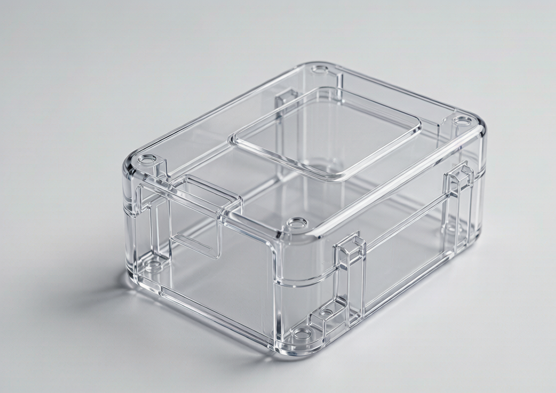
- Part Transparent electronic housing
- Material Clear PC
- Quantity 5 pcs
- Process 5-axis CNC machining
- Finish Fine machining + polishing
- Requirement Internal component visibility + assembly validation
- Inspection Dimensional + visual
Result: The customer validated internal assembly and clearance before committing to production tooling.
Why Choose Goldcattle for Clear PC Prototypes?
Multi-Process Capability
CNC + injection molding + 3D printing under one roof — we recommend the process, not just the machine we own.
Prototype to Production
Clear PC prototype → rapid tooling / injection molding, so the funnel continues past validation.
3 / 4 / 5-Axis
Complex transparent parts with fewer setups and better critical-face control.
Engineering Review
We confirm transparent areas, wall thickness, polishing needs and tolerances before cutting.
Inspection
CMM / dimensional / visual inspection matched to the stated requirement.
Prototype Quantity
1 piece minimum — start validation from a single part.
ISO 9001:2015 certified · Founded in 1998 · 100+ production machines · Virgin material on request
Request a Clear Polycarbonate Prototype Quote
Need crystal-clear, impact-resistant PC prototypes for your next design validation? Upload your 3D CAD models for a fast quote and free DFM analysis. Tell us whether you need visual transparency, functional testing or optical performance — we will recommend CNC machining, rapid tooling or injection molding based on your prototype requirements.
When you request a quote, include: CAD file, quantity, material, application, transparency level (visual / functional / optical), surface requirement, and any critical transparent surfaces marked on the drawing.
Frequently Asked Questions
Can polycarbonate be used for rapid prototypes?
Yes. Clear PC is widely used for rapid prototypes where transparency plus impact resistance or heat resistance is needed.
Can clear polycarbonate be CNC machined?
Yes. CNC machining is one of the most direct ways to produce real-PC transparent prototypes with good dimensional control.
How transparent can a CNC-machined PC part be?
It depends on material grade, machining marks, polishing method and part geometry. After finishing, clear PC reaches strong visible transparency; if transmission or haze is a defined acceptance criterion, the grade and finishing route are selected against that spec.
Is polycarbonate clearer than acrylic?
Not usually. PMMA / acrylic generally offers higher optical clarity, while PC leads on impact and heat resistance. Choose by priority, not by assumption.
What is the difference between clear PC and PMMA?
PC prioritizes toughness and heat resistance; PMMA prioritizes maximum optical clarity and scratch resistance. See the comparison above.
Can CNC-machined PC be polished?
Yes. Fine sanding and mechanical / specialty polishing raise transparency for visual and functional prototypes. The method is selected to the required clarity.
How do you prevent scratches on clear PC prototypes?
Correct tooling and feeds, careful handling, protective packaging and — where needed — hard-coat options reduce scratch risk.
Can clear polycarbonate be used for functional testing?
Yes. Because it is real PC, a CNC prototype gives mechanically relevant results for assembly, impact and thermal checks better than many transparent 3D-printed parts.
Is clear PC suitable for optical prototypes?
Only when the optical requirement is defined explicitly. "Clear" is not the same as "optical-grade." Light-path parts need a separate specification and process review.
What is the best process for transparent prototypes?
It depends on quantity, geometry and what you must learn. CNC for functional real-PC parts; 3D printing for fast concept; injection molding for production-intent. See the decision guide.
Should I choose CNC or 3D printing for a clear prototype?
Choose CNC when material authenticity and functional testing matter; choose transparent 3D printing for fast, low-cost concept and form validation.
Is CNC-machined PC the same as injection-molded PC?
No. A CNC prototype lacks mold-specific behavior such as shrinkage, weld lines, gate vestige and molded-in stress. For those, move to rapid tooling / injection molding.
How much does a clear PC prototype cost?
Cost depends on material grade, geometry, machining time, transparency requirement, polishing and inspection. Transparent finishing can be a meaningful share of the total.
How long does clear PC rapid prototyping take?
Typically 3–7 business days for CNC with polishing, confirmed against your part's geometry, quantity and surface requirement.
Can you make transparent PC parts in China?
Yes. Goldcattle is a China-based OEM/ODM manufacturer producing clear PC prototypes and production parts for global buyers.
Can you transition the prototype into injection molding?
Yes. A common path is clear PC prototype → rapid tooling / injection molding for production-intent validation and volume.