Custom CNC Machined Sensor Mounts & Precision Mounting Brackets
A sensor mount is not a generic bracket. It fixes where a sensor sits, which way it points, and whether it returns to the same place after maintenance. This page explains how those interfaces are specified, machined and inspected — and where a standard catalogue part is the better buy.
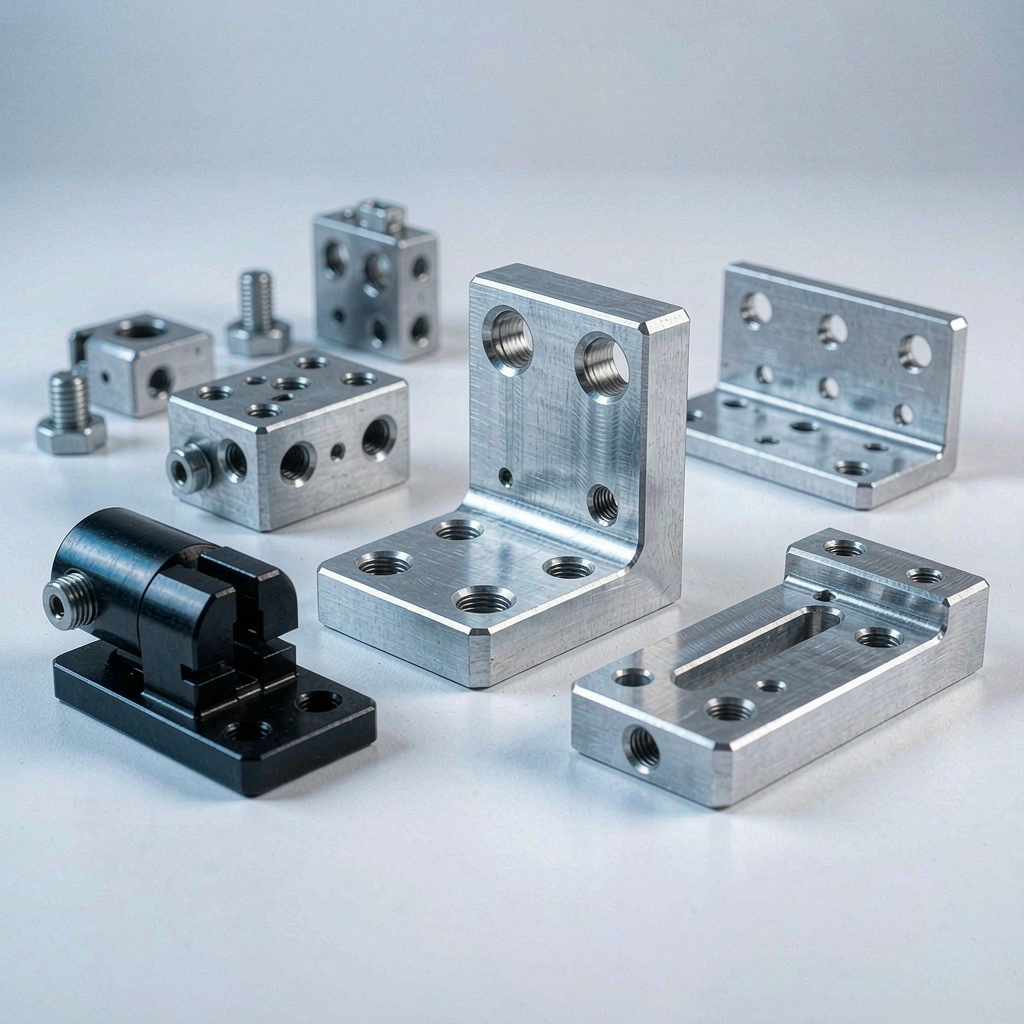
At a glance
CNC machined sensor mounts are custom-machined mechanical components that position and secure industrial sensors on machines, fixtures, robotic systems and inspection equipment. They include mounting brackets, cylindrical holders, positioning blocks, adjustable plates and multi-sensor supports, manufactured to a specified sensor interface and equipment mounting requirement. They are mechanical parts — not electronic sensors, and not a guarantee of sensing performance.
What We Manufacture — and What We Do Not
Our scope is the machined mechanical component: the bracket, holder, block, plate or rail that locates a sensor in an assembly. We work from a 2D engineering drawing and, where available, a 3D CAD model, plus the sensor model or the manufacturer's mounting dimensions. The output is a part inspected against that drawing — a sensor bore, a seating face, a hole pattern, an adjustment slot, a datum structure.
This page is deliberately not another overview of CNC machining. Our CNC machining services page covers the equipment and processes; the tight tolerance machining page covers general precision capability. Here we deal only with the decisions that change when the part has to hold a sensor: which dimensions are functional, what has to stay aligned after the bracket is removed and refitted, and what space the connector needs.
There is also a commercial boundary worth stating plainly. For a conventional M12 or M18 sensor in an open, unobstructed position, a catalogue bracket is often the correct purchase — faster and cheaper than a machined part. Custom machining earns its place when equipment space is constrained, when several sensors must hold a fixed relationship, when the mount has to survive vibration, when an angle or offset is non-standard, or when a discontinued OEM part has to be reproduced. We do not recommend custom machining where a standard part satisfies the requirement.
Where we draw the line
- We do not manufacture electronic sensors, connectors, cable assemblies or complete detection systems, and we do not calibrate sensors.
- We do not certify sensing performance, machine-vision recognition accuracy, optical calibration or the final validation of your assembled machine. Those belong to the sensor manufacturer and the equipment OEM.
- We do not claim cleanroom manufacturing or clean packaging for semiconductor applications unless a specific process and facility are agreed in writing.
- We do confirm the achievable tolerances, inspection method and documentation scope against your drawing at engineering review, in writing, before a price is issued.
Seven Sensor Mount Geometries
The structures below are a classification of mounting requirements, not a stock list. Each is a different answer to a different assembly problem, and each changes which dimensions become critical. Where we show a representative part, it is an illustration of a geometry to discuss at engineering review — not evidence of an existing catalogue product or a delivered customer order.
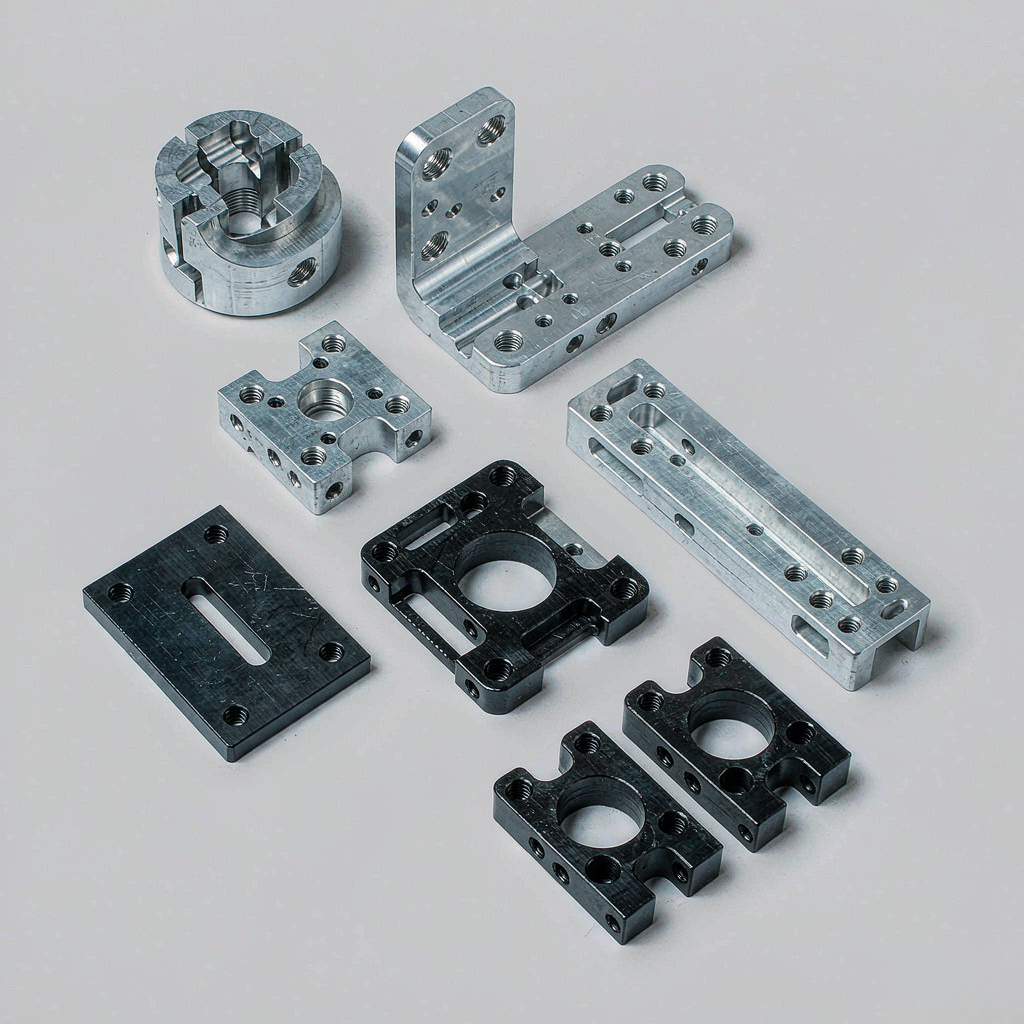
| Geometry | What it solves | Machining focus |
|---|---|---|
| Cylindrical sensor mounts | Holding a threaded cylindrical proximity or capacitive sensor | Bore diameter and fit, coaxiality, split and clamp screw, lock-nut clearance, seating face |
| Right-angle & offset brackets | Reaching a mounting position where space is constrained | Perpendicularity between faces, flatness of the mounting face, hole spacing, section stiffness |
| Adjustable mounts | Setting an angle or position during commissioning | Slot width and usable travel, clamping face, locking method, position stability after tightening |
| Multi-sensor blocks & rails | Keeping several sensors at a fixed spacing | Common datum, bore-to-bore pitch, parallelism, overall straightness |
| Vision & camera mounts | Locating a camera or optical sensor relative to a target | Reference surfaces, optical centre position, lens clearance, obstruction-free path, low-reflection finish |
| Encoder & measurement mounts | Relating a read-head to a scale or measured axis | Centre-line position, datum structure, read-head mounting relationship |
| Paired through-beam brackets | Aligning a transmitter and receiver across an axis | Shared datum, relative position between the pair, assembly marking, inspection as a set |
Sensor Compatibility: Model, Body and Metal Clearance
This is the section most generic bracket pages leave out, and the one that causes the most rework. Writing M12 on a drawing does not define the mechanical interface. Actual body diameter, thread length, lock-nut size across flats, mounting depth, sensing-face projection and connector style all vary between manufacturers and model families — including between two sensors that share the same nominal thread size.
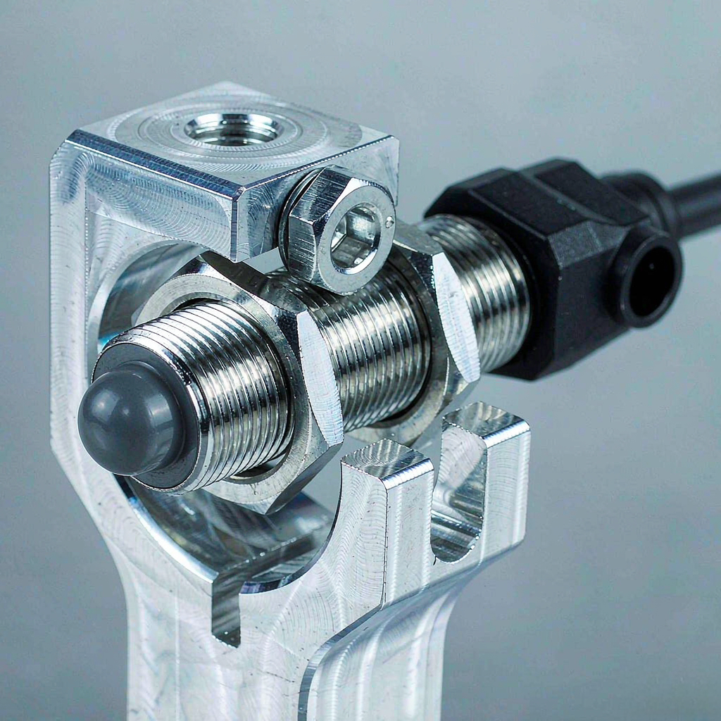
| Sensor type | Typical mounting requirement |
|---|---|
| Inductive proximity | Cylindrical bore, clamping or threaded interface; metal clearance must follow the model's flush or non-flush installation instructions |
| Capacitive | Model-specific body clearance and mounting interface; surrounding material affects the sensing field |
| Photoelectric | Fixed mounting hole pattern with controlled beam orientation |
| Laser | Accurate directional mounting and unobstructed beam path |
| Ultrasonic | Specified sensor-axis orientation and an unobstructed field |
| Vision sensor / camera | Stable reference surfaces, optical positioning and lens clearance |
| Encoder | Read-head mounting with a defined mechanical reference |
| Limit switch | Adjustable mounting with secure locking |
Metal clearance is a design decision, not a drilling operation
For inductive proximity sensors in particular, the surrounding metal changes the sensing condition. Whether a model is intended for flush or non-flush mounting, and how much free metal-free space it needs around the sensing face, is defined in that manufacturer's installation instructions. A machined bracket that grips the body correctly can still make the sensor behave incorrectly if it surrounds the face with aluminum.
The same applies to sensing-face projection. A clamp mount has to locate the sensor axially so that the face sits where the machine expects it — neither recessed behind the bracket nor protruding into a moving part. That axial position, the wrench space for two lock nuts, and the thread runout all belong on the drawing as dimensions, not as assumptions left to the fitter.
Repeatable Positioning After Maintenance
A sensor bracket is often removed during maintenance — to replace a sensor, clean a station or service a conveyor — and then bolted back. If its location depends only on clearance around ordinary bolt holes, the fitter has to re-align it by eye or by re-teaching the machine. The position after reassembly is then not the position that was commissioned.
The mechanical answer is a defined datum structure. Five features do most of the work, and they are inexpensive to add at the design stage but expensive to retrofit:
Paired through-beam brackets raise the same problem one level higher: the two halves must share a datum so their relative position, not just each half's own dimensions, is controlled. We recommend dimensioning the pair on one drawing, marking left and right physically, and inspecting them as a set. If the assembly has to be re-aligned after every service interval, the datum scheme is missing — and that is a drawing issue we will raise at review rather than machine around.
Connector, Cable and Tool Access
A bracket can hold every dimension on the drawing and still be impossible to install. Connectors are bulkier than the sensor body, cables need a bend radius, and a lock nut needs wrench clearance. These are volume requirements in the assembly, so they have to be checked against the equipment model, not against the bracket in isolation.
- Connector envelope. M8 and M12 connectors differ in diameter and length, and a right-angle connector occupies a very different volume from a straight one.Provide the connector drawing
- Cable exit direction. The exit has to point into free space, clear of framing, guards and moving parts.Mark it on the assembly
- Connector removal space. Enough axial room to unplug the connector without removing the bracket.Check at maintenance
- Tool access. Wrench clearance for lock nuts, and driver access to clamp screws and mounting bolts.Check with the tool, not the CAD view
- Cable bend space. Minimum bend radius and a route to the cable carrier or clip.Confirm with cable spec
Where an adjustable slot is present, access has to be checked at both ends of the travel — a connector that clears at the nominal setting may foul the frame at full extension. We ask for the connector and cable envelope at the first enquiry so these checks happen before the process plan is fixed. A photograph of the existing installation is often more useful here than another CAD view.
Precision Features and GD&T — Not One Blanket Number
Precision requirements are established around the functional mounting interfaces, including sensor bores, locating faces, hole patterns and alignment features. Critical tolerances are reviewed against the drawing and verified using appropriate dimensional inspection methods. We do not apply a single tolerance value to every feature of every part.
| Critical feature | Why it is functional | Typical control on the drawing |
|---|---|---|
| Sensor bore | Diameter, fit and coaxiality determine how the body sits | Diameter tolerance, position, sometimes concentricity |
| Sensor seating face | Contact surface that sets axial position and attitude | Flatness, perpendicularity to the bore axis |
| Mounting datum | The reference all other features relate to | Datum scheme identified on the drawing |
| Hole pattern | Bolt and sensor hole positions relative to the datum | True position, basic dimensions |
| Perpendicularity | Angle between mounting faces on right-angle brackets | Perpendicularity to a stated datum |
| Parallelism | Relationship of paired faces or multi-sensor rails | Parallelism to a stated datum |
| Dowel pin bore | Positive location after removal and refitting | Diameter fit and true position |
| Adjustment slot | Usable travel and clamping behaviour | Width, length, end radii, surface finish |
| Threaded holes | Clamping and mounting integrity | Thread specification, depth, thread quality |
| Surface finish | Contact, appearance and cleaning behaviour | Roughness callout where functionally needed |
Achievable values depend on the material, part size, wall stiffness, the number of setups and the inspection method available for that characteristic. A very tight true position on a thin, long rail is a different manufacturing problem from the same callout on a compact block. We confirm what is achievable in writing at engineering review, per feature, rather than quoting a machine's best-case capability as a batch guarantee.
For machine-vision mounts, one more interface deserves its own callout: the relationship between the mounting datum and the optical centre or lens axis. We can machine and measure that mechanical relationship. We cannot, and do not, guarantee the resulting recognition accuracy of the vision system — that depends on the camera, lens, lighting, calibration and the machine as a whole.
Materials and Finishes
Material choice here follows three things: the environment, the stiffness required, and the sensor's own installation constraints. Strength alone is a poor selector — an unnecessarily hard grade raises cost and machining time, and a metal chosen without reference to an inductive sensor's clearance requirement can create a sensing problem.
| Material | Where it fits | What to confirm |
|---|---|---|
| Aluminum 6061-T6 | General automation, vision and robotic mounts; light, readily machined, cost-balanced | Anodizing type and colour; whether a low-reflection finish is needed near an optical path |
| Aluminum 7075-T6 | Compact or highly loaded mounts where higher strength is specified | Whether the extra strength is actually required — many mounts are adequately served by 6061-T6 |
| Stainless 303 | Metal mounts where machinability dominates | Corrosion and mechanical requirements of the real environment |
| Stainless 304 | General corrosive or washdown environments | Cleaning agents, temperature and crevice conditions |
| Stainless 316 / 316L | Chloride exposure or demanding cleaning regimes | Actual medium and concentration; passivation requirement |
| Carbon steel | Where stiffness and cost dominate | Corrosion protection — plating or coating — and its effect on fit dimensions |
| POM / PEEK | Insulating, low-mass or chemically specific structures | Rigidity, temperature, creep and dimensional stability over time |
Common finishes include clear or black anodizing for aluminum, passivation for stainless steel, and plating or coating for carbon steel. Black anodizing is often requested for vision mounts to reduce stray reflections, but the finish thickness affects bore and pin fits, so it has to be accounted for in the machining dimensions rather than added afterwards. All grades, conditions and finishes are confirmed against the drawing and the service environment at quotation; we do not publish a fixed stock list as a capability claim.
Process Selection: When CNC Is Not the Answer
A flat mounting plate with four holes does not need five-axis machining. A bracket with several mounting faces at compound angles may. The engineering value is in matching the process to the geometry, not in applying the most capable machine to every part — an approach that raises cost without improving the sensor's position.
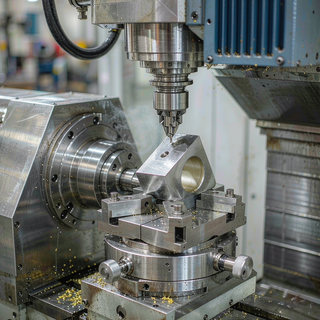
| Process | Suited to | Selection logic |
|---|---|---|
| 3-axis CNC milling | Flat plates, simple locating blocks, single-face hole patterns | Lowest setup count and cost for prismatic parts |
| 4/5-axis machining | Multi-face bores, compound angles, angled sensor axes | Reduces re-clamping and preserves datum relationships between faces |
| CNC turning | Cylindrical sensor holders, sleeves, ring-shaped clamps | Best concentricity between bore, outer diameter and seating face |
| Sheet metal fabrication | Simple light-duty bent brackets | Better material utilisation and cost where flatness and bore fit are not critical |
| Stamping | High-volume simple brackets | Tooling investment only makes sense at volume; not for one-off interfaces |
Setup count is the underlying constraint on this part. Every time the workpiece is released and re-clamped, the relationship between a bore on one face and a datum on another is re-established with some error. Where the drawing calls a tight true position across two or three faces, we plan a sequence that keeps those features in one clamping — or we tell you at review that the callout cannot be held as drawn and propose a datum change. That conversation is cheaper before the first chip than after the first article.
DFM and Engineering Review
Before a price is issued, the drawing and sensor information go through a review that asks practical assembly questions. These are the ones that most often change a design:
- Is there enough room for the sensor body and for its sensing-face projection at the specified position?
- Is there wrench clearance for both lock nuts, and driver access for the clamp screw, in the assembled state?
- Do the mounting holes weaken the section where the bracket has to stay rigid under machine vibration?
- Are dowel pin holes needed so the bracket can be removed and refitted without losing its position?
- Do the connector, cable and tool envelopes clear the frame at both ends of any adjustment travel?
- Can the number of setups be reduced by changing a face, a hole direction or the datum scheme?
- Which characteristics must be inspected and reported at first article, and which are covered by general tolerance?
The output of this review is a written process plan: datum scheme, setup sequence, inspection method, achievable tolerances per critical feature, and the documentation scope. If a feature cannot be made as drawn, we say so with an alternative rather than quietly substituting a near-enough interpretation.
Send the drawing before the design is frozen
Early review catches connector clearance, datum and setup issues while they are still cheap to change. Send your 2D drawing, CAD model and sensor model for a manufacturing assessment.
Request a DFM ReviewQuality Inspection and Documentation
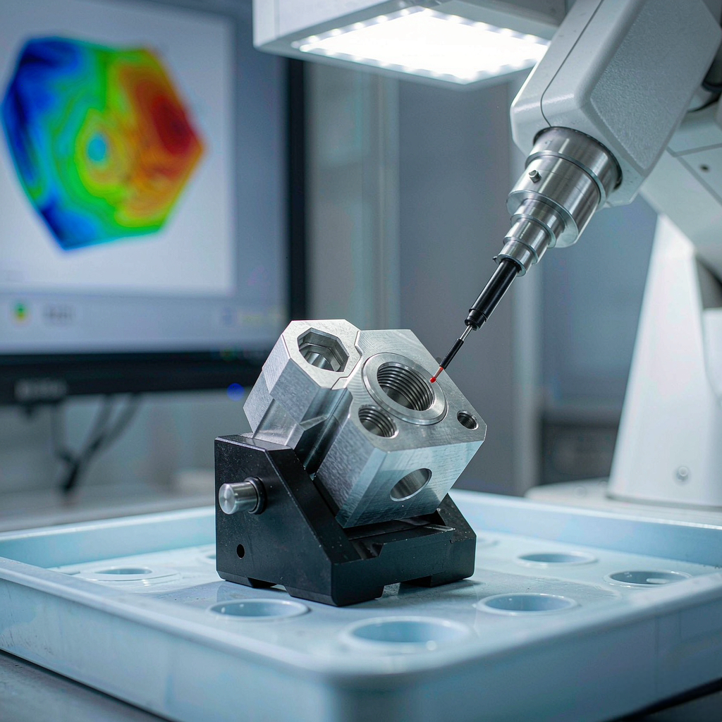
Inspection is planned around the functional interfaces identified in the drawing review. A part can hold every linear dimension and still fail in service if a bore is out of position relative to the datum, or if a seating face is not flat where the sensor bears against it.
| Characteristic | Typical verification | Risk if not controlled |
|---|---|---|
| Sensor bore diameter & fit | Calibrated bore measurement; gauge where specified | Loose clamping, sensor movement under vibration |
| Hole position / true position | CMM against the stated datum scheme | Sensor axis misaligned relative to the target |
| Seating face flatness | Precision measurement or CMM | Sensor attitude error, unstable contact |
| Perpendicularity / parallelism | CMM or suitable precision setup | Beam or optical axis off direction |
| Dowel pin bore fit | Calibrated measurement against pin specification | Position lost after maintenance |
| Thread specification & depth | Thread gauge and depth check | Clamp screw or mounting bolt will not seat |
| Paired bracket relationship | Inspection of the pair against one datum | Through-beam pair misaligned on reassembly |
Who Buys These Parts, and What They Check
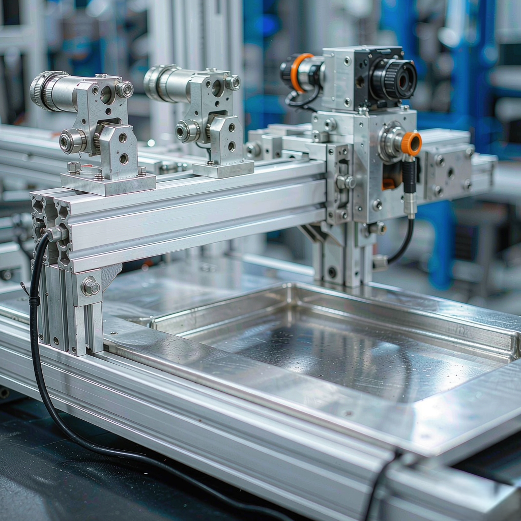
Industrial automation OEMs
Assembly, packaging, conveying and inspection equipment. Constrained space, mixed sensor brands, fixed sensor spacing and vibration. They check bore position, seating face flatness, sensor-axis direction and whether maintenance preserves the original datum.
Robotics & AMR / AGV builders
LiDAR, encoder, proximity and camera mounts on moving structures. Weight, rigidity and positional stability under motion dominate. We can machine the mechanical interface; we do not guarantee the resulting vision or navigation accuracy of the system.
Machine vision & optical inspection OEMs
Camera plates, optical blocks, lens holders and calibration fixtures. They need defined reference surfaces, a clear optical path and controlled parallelism or perpendicularity — the mechanical relationship to the optical centre, not the recognition result.
Semiconductor & metrology equipment
Wafer handling, measurement and test equipment. Critical dimensions, material stability, rigidity and documented traceability. Cleanroom manufacturing or clean packaging is not claimed unless a specific agreed process exists.
Replacement & retrofit buyers
Damaged brackets, discontinued OEM parts, new sensor models on old machines, or sample-based reproduction. A photograph and the old part are often the fastest route to a usable drawing and a first article.
What all five actually want
Not a capability brochure. They want to know whether their sensor will fit, whether the position will hold, whether the connector has room, and what evidence arrives with the parts. Those are the questions the rest of this page answers.
From Prototype to Repeat OEM Orders
Prototype quantities start from one piece, subject to drawing review and process setup. Prototype and production orders are quoted separately: setup, inspection scope and unit cost differ, and a sample made on a general setup should not be priced as though it were a repeat batch. Tell us the expected annual or repeat volume at the first enquiry so the fixture and datum scheme are chosen for the production route, not only for the sample.
Custom mounts are economical to reorder only when the second batch is genuinely the same part. The items below are frozen after first-article acceptance; changing any one of them is a new engineering review, not a purchasing detail.
| Frozen item | Why it is controlled |
|---|---|
| Drawing revision and critical characteristics | Defines the acceptance basis for every later batch |
| Sensor make, model and interface dimensions | A new model changes bore, projection and clearance |
| Material grade, condition and finish specification | Changes machinability, fit after coating and appearance |
| Fixture, datum scheme and setup sequence | Protects bore-to-datum relationships across batches |
| Tooling and gauge references | Keeps the same acceptance basis in use |
| Inspection plan and report format | Prevents a conforming batch being judged against a new standard |
RFQ Checklist — What to Send
The fastest quotations come from enquiries that include the sensor and the assembly, not only the bracket. A drawing without the sensor model usually generates one round of questions before engineering review can start.
Frequently asked questions
What are CNC machined sensor mounts?
CNC machined sensor mounts are custom-machined mechanical components that position and secure industrial sensors on machines, fixtures, robotic systems and inspection equipment. They include mounting brackets, cylindrical holders, positioning blocks, adjustable plates and multi-sensor supports, manufactured to a specified sensor interface and equipment mounting requirement. They are mechanical parts, not electronic sensors or complete detection systems.
Can you manufacture custom sensor mounts from drawings?
Yes. We work from your 2D engineering drawing and, where available, a 3D CAD model in STEP or IGES, together with the sensor model or its manufacturer's mounting dimensions. Engineering review covers the sensor bore, locating faces, hole pattern, adjustment features, connector clearance and material before quotation. We do not hold catalogue stock of standard sensor brackets; each part is planned against the drawing.
What sensor types can your mounting brackets support?
Mounting brackets can be designed around inductive proximity, capacitive, photoelectric, laser, ultrasonic and vision sensors, as well as encoders and limit switches. The sensor type determines the mechanical interface: a cylindrical threaded body needs a bore and lock-nut access, a photoelectric sensor needs a fixed hole pattern and beam orientation, and a camera needs stable reference surfaces and a clear optical path.
Which materials are suitable for sensor mounting brackets?
Aluminum 6061-T6 suits general automation and vision mounts where weight and machinability matter; 7075-T6 is considered where higher strength is specified. Stainless 303, 304 and 316 or 316L are used where corrosion, cleaning agents or washdown conditions apply. Carbon steel, POM and PEEK are assessed per project. Grade, condition and finish are confirmed against the drawing and service environment at quotation.
Can you machine sensor mounts with adjustable slots and locating pins?
Yes, where the drawing calls for them. Adjustment slots define usable travel and need a clamping face that holds position after tightening; locating pin bores and machined reference faces let a bracket be removed for maintenance and returned to the same position. Slot width, pin fit, datum scheme and locking method are reviewed together, because an adjustable feature without a repeatable lock is not a stable mount.
What tolerances can you achieve for sensor mounting interfaces?
Precision requirements are established around the functional mounting interfaces — sensor bores, seating faces, hole patterns, datum relationships and alignment features — rather than one blanket number for the whole part. Achievable tolerances are reviewed against the drawing, material, geometry and inspection method, then confirmed in writing at engineering review. We do not claim a universal tolerance for every feature and batch.
Can you produce prototype and repeat batches?
Prototype quantities start from one piece, subject to drawing review and process setup. Prototype and production orders are quoted separately because setup, inspection scope and unit cost differ. For repeat orders we retain the drawing revision, material condition, fixture and datum scheme, tooling references and inspection plan so later batches are measured against the same basis as the first article.
What information is needed for a sensor mount quotation?
Send the 2D drawing and 3D CAD, the sensor make and model or its mounting dimensions, the manufacturer's installation instructions where metal clearance matters, connector and cable exit direction, material and finish, critical characteristics and geometric dimensioning and tolerancing callouts, quantity, sample stage, target delivery, and any first-article or documentation requirements. A photograph of the existing installation helps for retrofit projects.
Can you manufacture complete industrial sensors?
No. We manufacture the mechanical mounting components — sensor brackets, cylindrical holders, mounting blocks, positioning plates and adjustable supports. We do not manufacture electronic sensors, cable assemblies, connectors or complete detection systems, and we do not calibrate sensors. Sensing performance, optical alignment and final machine validation remain the responsibility of the equipment OEM and the sensor manufacturer.
Questions buyers ask before sending an RFQ
Do I need a custom machined mount, or will a catalogue bracket work?
If a standard M12 or M18 sensor sits in open space with a conventional hole pattern, a catalogue bracket is usually the better buy. Custom machining is justified by constrained space, several sensors on one datum, non-standard angles or offsets, vibration and stiffness requirements, repeatable positioning after maintenance, or reproducing a discontinued part.
We would rather say so at the enquiry than quote a machined part for a need a stock item already satisfies.
Can one mount design cover several sensor models?
Sometimes, with a clamp or adapter interface — but nominal thread size is not enough to decide. Body diameter, thread length, lock-nut size, sensing-face projection and connector style vary by model. If the production line uses more than one sensor, send both models and we will tell you whether one shared interface is viable or two part numbers are safer.
Two part numbers with separate drawings are cheaper than one ambiguous drawing and a mixed batch.
How do you keep the sensor axis aligned across a batch?
By holding the bore, seating face and hole pattern to one datum scheme in a planned setup sequence, then measuring the true position and perpendicularity relationships on the agreed method. Where a tight relationship spans several faces, we plan a single-clamping sequence. The inspection plan is part of the quotation, not an afterthought.
Related: precision features · inspection plan
What if the bracket has to come off for maintenance?
Then the drawing needs a repeatable assembly interface: dowel pin bores, machined locating faces, a defined reference edge and a controlled hole pattern relative to those datums. Without them, bolt-hole clearance becomes the location tolerance and the fitter has to re-align the sensor after every service interval.
Related: repeatable positioning
Related Capability Pages
This page covers one component family. For the wider process, precision and material background, see the capability pages below.
Submit Your Sensor Mount Drawing
Send your 2D drawing, 3D CAD, sensor model and connector envelope. Our engineering team reviews the mounting interfaces, metal clearance, datum scheme, process route and inspection requirements, then confirms achievable tolerances and the process plan in writing before a price is issued.
Request a QuoteDrawings are handled under our standard confidentiality procedure; an NDA can be arranged before files are exchanged.