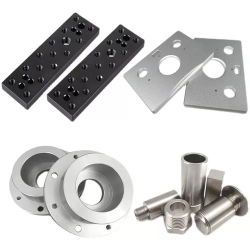
CNC Milling vs Turning: Choosing the Right Shape-Making Process
Milling and turning are the two core subtractive processes behind precision metal and plastic parts. The right choice depends on part geometry, feature relationships, tolerances and volume — not on which machine looks more capable.
At a Glance
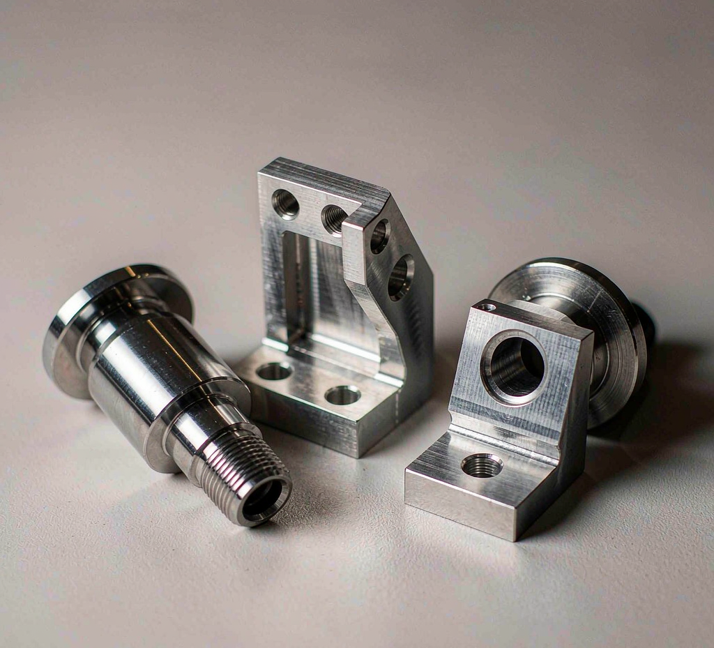
Pick the process from the dominant geometry. Milling is for prismatic and 3D parts where the tool moves to a stationary workpiece. Turning is for round parts where the workpiece spins. When a part has both turned diameters and off-axis features, mill-turn in a single setup usually wins on accuracy and lead time. The decision should follow the part, not the machine.
How Milling and Turning Work
Both are CNC subtractive processes, but they move differently. Understanding the motion explains almost every downstream consequence for geometry, tolerances and cost.
Tool rotates, part is fixed
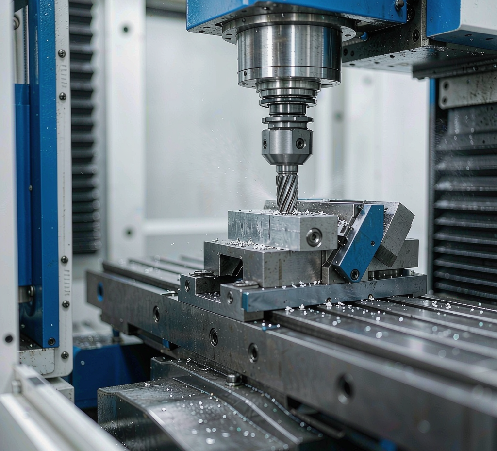
A multi-point cutter spins in the spindle while the table moves the stationary workpiece along X, Y and Z. This reaches flat faces, pockets, slots, ribs and 3D contours from almost any angle.
Part rotates, tool is fixed
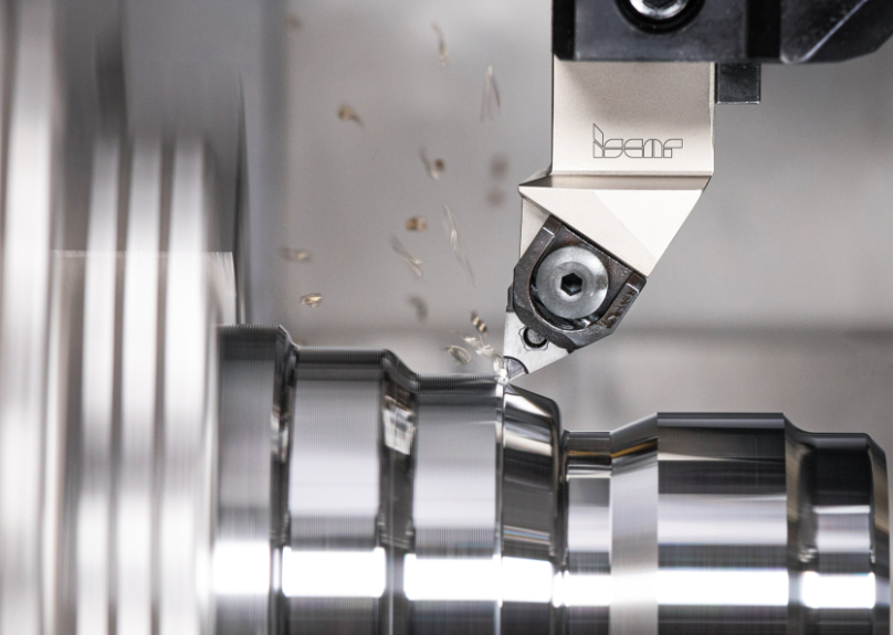
The workpiece spins in a chuck or collet against a single-point tool. Material is removed as the tool feeds along the axis, producing cylinders, cones, bores and threads with strong concentricity.
Both on one spindle
A turning center with live tooling rotates the part for turning, then drives stationary cutters for milling, drilling and slotting — all without unclamping. One setup covers round plus off-axis features.
Nine Factors That Decide the Process
Use this checklist when a drawing reaches engineering. The first three usually settle the decision; the rest refine cost and lead time.
Dominant shape
Round and symmetric leans turning; flat, prismatic or 3D leans milling. A mix leans mill-turn.
Shared axis vs pattern
Concentric diameters favor turning; hole patterns and off-axis features favor milling or mill-turn.
Where accuracy matters
Tight roundness on a diameter favors turning; tight position between non-axial features favors milling.
Stock form
Bar stock suits turning; plate or block suits milling. Material also drives tooling and cycle time.
Quantity
Low and mid volumes suit both; very high volumes may shift economics toward dedicated tooling.
Speed to first part
Fewer setups shorten delivery. Mill-turn often ships complex parts faster than separate operations.
Setup and cycle
Setup count, cycle time and scrap risk dominate cost more than the hourly machine rate.
Threads, cross-holes
Live tooling can cut threads, drill cross-holes and mill flats in the same chucking.
What gets measured
Critical dimensions are confirmed by CMM. Define the datum scheme so relationships are verifiable.
When to Choose Milling
Choose milling when the part is prismatic or 3D — flat plates, brackets, housings, manifolds and fixtures — especially with pockets, slots, ribs or a hole pattern that does not share one axis.
Milling excels at geometry a lathe cannot reach. A 3-axis machine covers most orthogonal-face parts; 4- and 5-axis machines reach angled and contoured surfaces while keeping the part in one clamping.
- Brackets, mounting plates and enclosures with milled pockets and bolt patterns
- Housings and manifolds where internal cavities meet external 3D surfaces
- Fixtures, jigs and tooling components that must locate to tight datums
- Parts with features on multiple faces best reached without re-clamping
If your part is essentially round but needs a few off-axis features, read the mill-turn section before defaulting to a separate milling setup.
When to Choose Turning
Choose turning for round, cylindrical, conical or threaded parts — shafts, pins, bushings, spacers, fittings and fasteners — where tight concentricity across a shared axis is the priority.
Because the workpiece rotates about its own axis, turning holds diameter and roundness efficiently and produces threads, tapers and bores in a single chucking. Live tooling extends a lathe to drill axially and even mill simple flats without a second machine.
- Shafts and spindles where several diameters must stay concentric
- Bushings, sleeves and spacers defined by inner and outer roundness
- Fittings, connectors and threaded fasteners
- Bar-stock parts where the starting form is already round
When to Choose Mill-Turn
Choose mill-turn when a part has both turned diameters and off-axis features — a cross-hole, flat, hex or keyway — and you want them completed in one setup.
Mill-turn removes the clamping hand-off between turning and milling. The part is turned, then milled, drilled or slotted while still held, so the relationship between round and off-axis features is controlled by a single datum chain. This usually improves accuracy and shortens lead time versus separate operations.
Two setups, two datums, more handling, longer lead time, more chances for position error between features.
Single clamping, one datum chain, less handling, faster delivery, tighter control of feature-to-feature relationships.
Quick Selection Guide
Use this table as a first pass. Send the drawing for a confirmed process recommendation.
| If your part is mainly… | Milling | Turning | Mill-Turn |
|---|---|---|---|
| Flat plate with pockets and holes | Best | — | Possible |
| Round shaft with concentric diameters | — | Best | Possible |
| Turned body + cross-hole or flat | Two setups | Two setups | Best |
| 3D contoured surface | Best (4/5-axis) | — | Possible |
| Threaded fastener or fitting | — | Best | Best |
| Hole pattern on multiple faces | Best | — | Possible |
Design for Milling & Turning (DFM)
Good DFM protects tolerance, lead time and cost. Apply tolerance only where function demands it, and define a clear datum scheme so the shop can verify relationships.
Avoid extremes
Use standard internal radii the shop can reach with common tooling; avoid very sharp internal corners and tiny fillets that force special cutters.
Keep them stable
Thin walls and very deep, narrow pockets invite chatter and longer cycle times. Discuss proportions with engineering before locking the design.
Standard sizes
Favor standard drill and thread sizes. Axial holes suit turning; cross-holes and off-axis features are cleaner with live tooling or mill-turn.
One reference chain
Pick primary and secondary datums that the machine can actually locate. A consistent datum scheme makes CMM verification straightforward.
Real Example Builds
These generic build types show how the decision plays out. They illustrate process logic, not a specific customer order.
Hydraulic adapter fitting
- FormTurned body + hex + cross port
- ProcessMill-Turn, one setup
- WhyConcentric thread + off-axis port in one clamp
A round fitting needs a threaded body and a cross-drilled port. Doing both in one mill-turn setup keeps the port located to the thread axis and avoids a second operation.
Mounting bracket
- FormPrismatic plate with pockets
- ProcessMilling
- WhyHole pattern and ribs not on one axis
A flat bracket with a bolt pattern, lightening pockets and locating ribs is a milling part. 3-axis covers orthogonal faces; angled features would point to 4- or 5-axis.
Precision shaft
- FormLong cylinder, several diameters
- ProcessTurning
- WhyConcentricity across shared axis
A shaft with multiple diameters, a taper and a thread is turned for efficiency. Concentricity is held naturally because every feature rotates about the same axis.
Goldcattle CNC Capabilities
Xiamen Goldcattle Plastic & Metal Products Co., Ltd. is a precision manufacturer founded in 1998, running all six core processes in-house under one ISO 9001:2015 quality system. For milling and turning we offer:
3 / 4 / 5-axis
CNC machining centers for prismatic and contoured parts, from prototypes to production runs.
Lathe + live tooling
CNC lathes including Swiss-type and live-tooling turning centers for round and mixed parts.
Single-setup parts
Combined turning and milling that holds feature relationships in one clamping.
CMM verified
Critical dimensions confirmed by CMM, with documentation available on request.
We work in aluminum, steel, stainless steel, brass, titanium and engineering plastics, with prototyping in 3–7 business days and production in 15–25 business days. Minimum order is one piece. See the milling service guide and turning services for more detail, or the milling vs turning overview for a broader comparison.
Request a Process Review
Send the following so we can confirm the right process and return a quote:
Drawing
STEP, DXF or PDF with the geometry clearly defined.
Material & quantity
Grade or requirement, and the volume per order.
Tolerances & datums
Critical dimensions and the datum scheme to inspect against.
Finish & timing
Required surface finish and your target lead time.
Our engineering team confirms milling, turning or mill-turn and replies with a quote.
Frequently Asked Questions
What is the difference between CNC milling and turning?
CNC milling uses a rotating multi-point cutter to remove material from a stationary workpiece, producing flat surfaces, pockets, slots and complex 3D shapes. CNC turning holds the workpiece in a spindle that rotates it against a single-point cutting tool, producing cylindrical, conical and threaded shapes. The core difference is motion: in milling the tool moves and the part stays still; in turning the part rotates and the tool stays on a fixed axis.
Which is more precise, milling or turning?
Neither process is universally more precise. Turning typically holds tighter diameter and roundness on rotationally symmetric features because the part spins about its own axis. Milling typically controls the position and form of prismatic, off-axis and 3D features better because the spindle moves to each feature. Both reach tight tolerances on suitable features, and a CMM verifies the critical dimensions on request.
When should I choose milling?
Choose milling for prismatic parts: flat plates, brackets, housings, fixtures, manifolds and any part with pockets, slots, ribs or a pattern of holes that do not share one axis. Milling is also the right choice for complex 3D contours and non-round geometry that a lathe cannot produce.
When should I choose turning?
Choose turning for round, cylindrical, conical or threaded parts: shafts, pins, bushings, spacers, fittings and fasteners. Turning is the most efficient way to hold tight concentricity across diameters that all share a single axis.
What is mill-turn and when is it worth it?
Mill-turn combines turning and milling in one machine, so a part can be turned and then milled, drilled or slotted without being removed from the spindle. It is worth it when a part has both round diameters and off-axis features such as a cross-hole, flat, hex or keyway. Completing the work in one setup reduces handling, shortens lead time and improves the relationship between turned and milled features.
Can one part need both milling and turning?
Yes. Many production parts are a mix: a turned body with a milled flat, cross-drilled hole or off-axis port. If the volumes and tolerances justify it, that part is a strong candidate for mill-turn. If not, it can be produced as a turning operation followed by a separate milling setup, with inspection between steps.
How do I decide between 3-axis and 5-axis milling?
Use 3-axis milling for parts with features on one or a few orthogonal faces. Consider 5-axis milling when features sit on multiple angled faces, a continuous 3D surface is required, or you want to reach a feature without multiple setups. Fewer setups generally mean better feature-to-feature accuracy and shorter lead time, so 5-axis is often chosen for complex prismatic parts rather than for decorative effect.
What tolerances can CNC machining hold?
Achievable tolerance depends on the feature, material, machine and measurement method, so it should be confirmed per part rather than assumed from a single number. We review your drawing and datum scheme, hold the tolerance that the design actually requires, and verify critical dimensions with CMM inspection. Tolerances should be applied only where function demands them to keep cost and lead time reasonable.
How many setups are needed and why does it matter?
A setup is one clamping of the part in the machine. Each additional setup adds a datum hand-off and a chance for position error between features. Fewer setups — for example through mill-turn or smart fixture design — improve the accuracy of relationships between features such as hole patterns and concentric diameters, and they reduce handling time. The number of setups is a major driver of both quality and cost.
How do I get a quote for a milled or turned part?
Send your drawing in STEP, DXF or PDF form, the material and quantity, the critical tolerances and datum scheme, any required surface finish, and your target lead time. With that information we can confirm the suitable process — milling, turning or mill-turn — and return a quote. Use the request button on this page to start a process review with our engineering team.
Not sure whether your part should be milled, turned or mill-turned?
Send the drawing and our engineering team will confirm the process, review the datum scheme and return a quote. One piece is enough to start.
Request a Process Review Browse all CNC servicesXiamen Goldcattle Plastic & Metal Products Co., Ltd. — Founded in 1998 · ISO 9001:2015