Custom Industrial Sheet Metal Components for OEM Equipment Manufacturers
Goldcattle manufactures custom industrial sheet metal components — brackets, mounting plates, machine guards, covers, equipment panels, chassis and welded subassemblies — built from customer drawings. One integrated route takes each part from flat sheet to formed, finished and assembly-ready, with inspection and traceability built in.
At a Glance
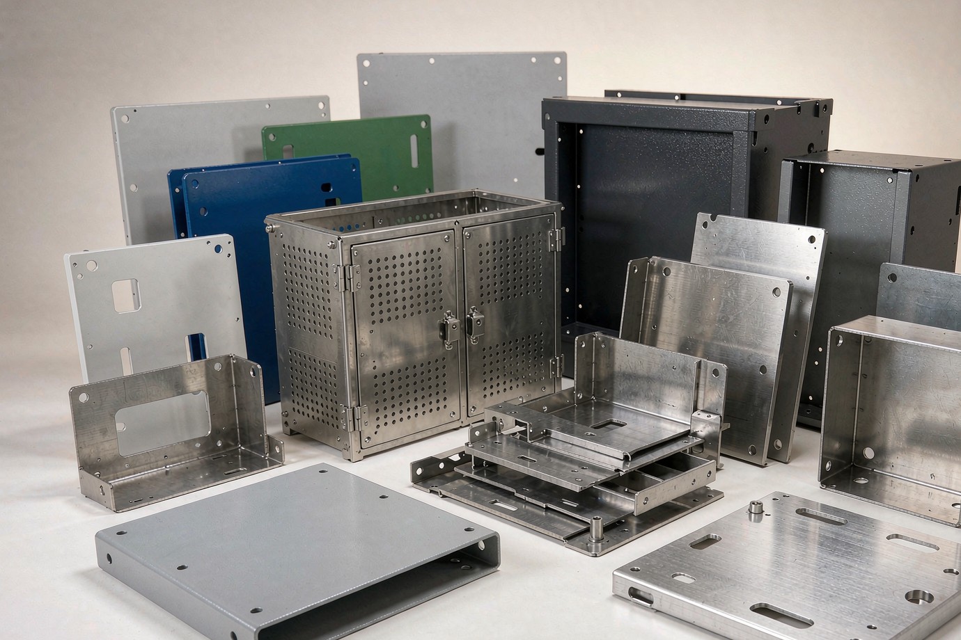
Custom industrial sheet metal components are build-to-print parts — machine guards, brackets, mounting plates, covers, equipment panels, chassis and welded subassemblies — produced for industrial-equipment OEMs from their drawings. Rather than selling machine time, the work is organized around the part and its assembly role: material and thickness, bend geometry, hole and interface positions, weld method and surface finish are controlled so the component fits and repeats. Cutting, bending, welding, PEM insertion and powder coating are coordinated under one quality system, with some anodizing/plating done through audited partners.
Industrial Sheet Metal Components We Manufacture
Industrial buyers usually purchase a part or subassembly that fits into a larger machine, not an isolated flat plate. The component families below are organized by function and assembly role so they map to real equipment needs. See also the broader sheet metal fabrication capabilities for the full process and equipment overview, and the custom sheet metal electronics enclosures page for control and electrical housing work.
Machine Guards & Covers
Access doors, removable service panels, ventilated and splash covers, and equipment housings that protect operators and internal parts.
Brackets & Mounting Plates
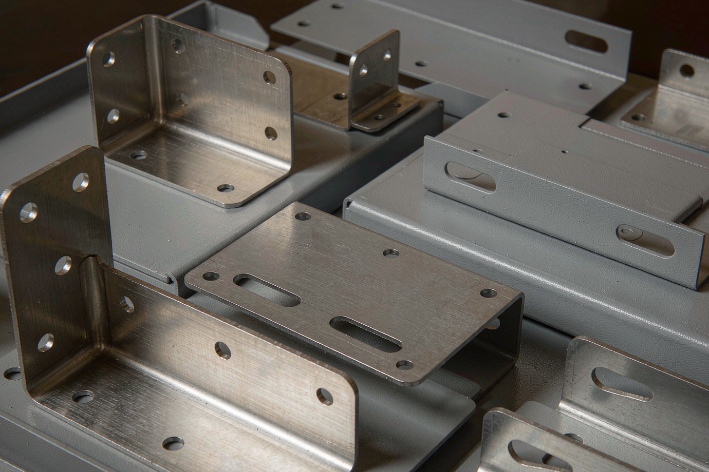
L/U/Z brackets, sensor and motor mounts, and DIN-rail or equipment mounting plates with controlled hole and flange positions.
Chassis & Equipment Panels
Front/back panels, base plates and equipment chassis where flatness, bend height and interface locations matter.
Trays & Cable Management
Cable covers, trays, support channels and tie-down structures that organize wiring and components inside the enclosure.
Ventilation & Airflow Parts
Ventilation panels, louvers, baffles and filter-mount frames that manage heat and airflow within the equipment.
Welded Subassemblies
Multi-piece brackets, covers, frames and mounting subassemblies welded and checked as a single delivered unit.
Sheet Metal Components for Industrial Equipment
The same component families serve several equipment types. Each application changes the priorities — a guard is judged on fit and service access, a bracket on load and vibration, a panel on flatness and EMI/grounding.
Industrial Machinery
Covers, guards, frames and mounting parts for production and processing equipment.
Automation & Robotics
Structural brackets, cable management and enclosures for automation cells and robotic bases.
Material Handling
Conveyor brackets, guards and support structures for transport and handling systems.
Electrical & Control Equipment
Mounting plates, panels and enclosures for control cabinets and power equipment.
HVAC & Filtration
Ventilation panels, filter frames and housings for air handling and filtration units.
Energy Equipment
Brackets, enclosures and support parts for power, storage and energy systems.
Materials and Specifications for OEM Sheet Metal Components
Material is chosen for the part's job — rigidity, weight, corrosion environment, formability, weldability and finish — not by a single shop-wide thickness claim. The table below lists the grades typically fabricated and their common working range; the exact thickness and process window are confirmed against the drawing in DFM rather than quoted as one blanket number.
| Material family | Typical grades | Common thickness (mm) | Where it is used |
|---|---|---|---|
| Carbon steel | CRS / SPCC / S235 | 0.8 – 4.0 | Brackets, panels, chassis, painted/coated parts |
| Stainless steel | 304 / 316 | 0.6 – 3.0 | Guards, food/clean environments, corrosion-exposed parts |
| Aluminum | 5052 / 6061 | 0.8 – 6.0 | Lightweight panels, brackets, enclosures |
| Galvanized steel | DX51D + Z | 0.8 – 2.5 | Outdoor and corrosion-protected structural parts |
| Copper / Brass | C1100 / C2600 | 0.5 – 2.0 | Conductive and EMI/grounding components |
Across the shop, fabricated gauges commonly span roughly 0.5 – 6.0 mm, but the usable range is material- and process-dependent: thin stainless and copper form differently from aluminum, and very thick plates move into a different bending and welding envelope. For aluminum-specific bending and finish guidance, see the precision aluminum sheet metal page.
Surface finishing — in-house vs external
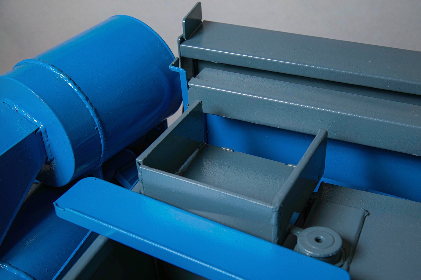
Powder coating (commonly 60–120 µm film) and basic mechanical finishes are performed on-site, giving control over masking, film thickness and lead time.
Anodizing and certain electroplating are completed by qualified external partners. These are named as external steps so the boundary of in-house work is stated honestly.
Integrated Industrial Sheet Metal Manufacturing
The value for an OEM is a single coordinated route, not six separate vendors. A typical part moves through flat-sheet processing, forming, joining and finishing before inspection and packaging.
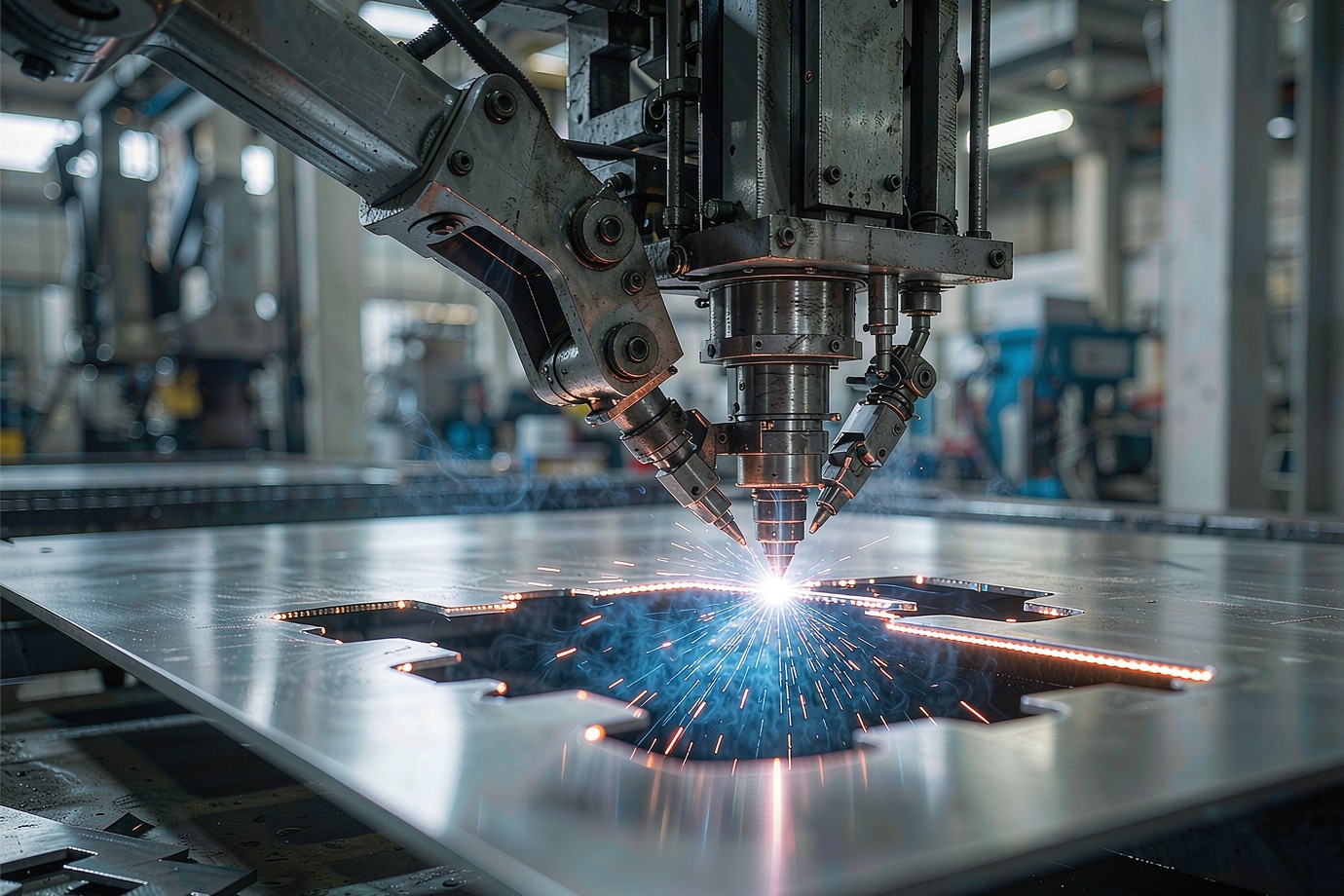
- Fiber laser cutting: defines contours, holes, slots and cut-outs from the flat pattern with tight positional accuracy.
- Turret punching: efficient for repeated hole arrays and formed features across larger batch quantities.
- CNC press brake bending: forms flanges, returns and brackets to controlled angles and bend heights.
- Stamping / progressive tooling: used where volume justifies dedicated tooling for a mature part.
- Welding (TIG / MIG / spot): joins multi-piece brackets, covers and subassemblies, with distortion and weld access reviewed up front.
- Hardware insertion: PEM-style nuts, studs and standoffs pressed and verified by position.
- Surface finishing: powder coating in-house; anodizing/plating through audited partners.
- Assembly: subassemblies built, fitted and packaged to the customer's BOM and labeling.
Engineering Considerations for Industrial Sheet Metal Parts
Most industrial sheet metal problems are solved before cutting, in the drawing and DFM review. The points below are what the engineering team checks against each part's function and assembly.
1 · Material and thickness selection
Material is matched to rigidity, weight, corrosion exposure, formability, weldability and finish. The same bracket can be over-built in one alloy and under-built in another; the choice is confirmed against the service load, not defaulted.
2 · Bend radius and flange design
Inside bend radius, flange length, bend relief, springback, grain direction and multi-bend interference are checked so the part forms cleanly and holds its shape.
3 · Hole and slot positioning
Hole-to-bend, slot-to-bend, hole-to-edge distances, countersink location and PEM hardware clearance are verified so features are not placed in the deformation zone of a bend.
4 · Stiffness and reinforcement
Large covers, brackets and panels gain rigidity through hems, flanges, stiffening beads and fastening strategy rather than simply increasing thickness.
5 · Weld distortion and assembly
Weld access, distortion, joint location, assembly datum, fastener access and post-weld finishing are planned so the welded unit meets its fit and dimensional targets.
6 · Surface finish requirements
Finish is selected by environment — powder coat, anodize, zinc plate, brushed or passivation — and the in-house/external boundary is stated so the scope is clear.
Quality Inspection and Dimensional Control
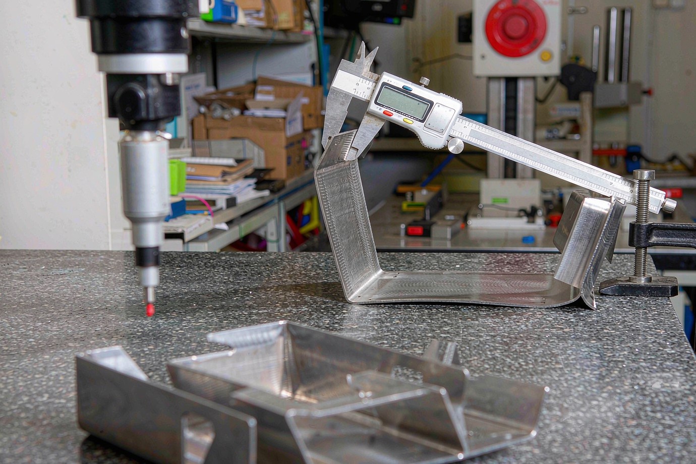
Inspection follows the part through its route. Each stage checks what that stage can actually control:
| Stage | Core checks |
|---|---|
| Incoming material | Grade, thickness and material certificate |
| Laser / punch | Contour, hole position, edge and burr |
| Forming | Bend angle, flange length, across-bend dimension |
| Welding | Weld quality, distortion, structural dimension |
| Hardware insertion | Fastener type, position and seating |
| Surface finishing | Film thickness, appearance, masked areas |
| Final inspection | Critical dimensions, assembly fit, packaging |
Three tiers of dimension control
Rather than one tolerance for the whole part, dimensions are controlled by class:
- General dimensions — overall length, width and flat-pattern edges, checked with calipers, rules and fixtures.
- Formed dimensions — bend height, bend angle and across-bend distance, checked with height and angle gauges.
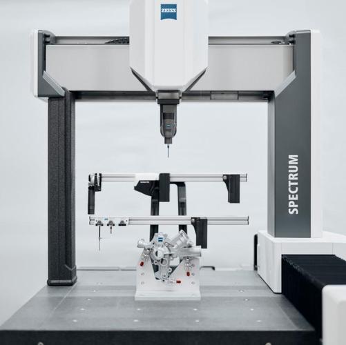
- Critical assembly dimensions — hole pitch, interface and datum positions — verified by CMM or dedicated locating fixtures.
Custom Industrial Sheet Metal Components — Project Examples
Component work is shown as build-to-print examples. The example below is illustrative of the information captured for a welded subassembly; actual parameters come from the customer drawing and are confirmed in DFM.
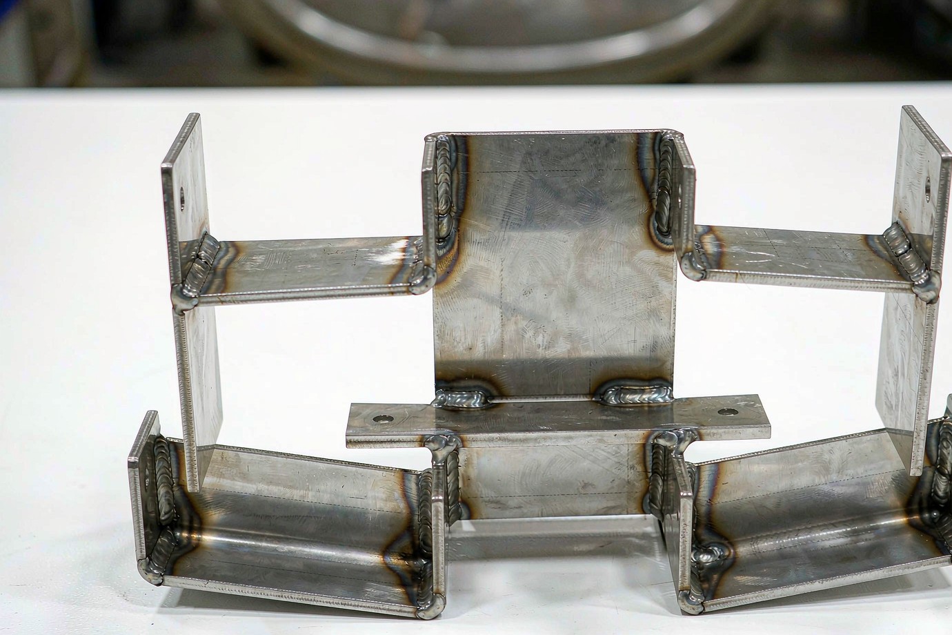
Example part (illustrative)
- PartWelded equipment bracket
- MaterialS235 / SPCC
- ProcessLaser + bend + TIG weld
- FinishPowder coat (in-house)
- Critical dimHole pitch, weld datum
- VolumePrototype → batch
Shown as an example of a build-to-print welded subassembly. Parameters are defined by the customer drawing; the same route applies to guards, panels, trays and other component families.
From Engineering Drawing to Repeat Production
A multi-part equipment project is managed as one flow so reorder is consistent:
RFQ & BOM
Drawing, material, quantity and inspection scope submitted.
DFM Review
Bend, hole, weld and tolerance check against function.
Quotation
Price, lead time and batch plan returned.
First Article
FAI and sample approved before production.
Production
Cutting, bending, welding, finishing, assembly.
Inspection
In-process and final checks with traceability.
Packaging
Export packaging and shipping to destination.
For early-stage parts, the low-volume sheet metal prototyping route supports fast first samples before batch commitment.
Request a Quote
The list below is a checklist of what to include in your RFQ — there is no form on this page; submit your drawing and BOM through the quote button, which opens the secure RFQ window.
What to include in your OEM sheet metal RFQ
Send these details with your drawing. The more the drawing and BOM define, the faster the review.
BOM projects: if the components belong to a larger equipment assembly, include the part list together. One project owner coordinates manufacturing and delivery across the related parts, which is easier to manage than separate one-off inquiries.
Frequently Asked Questions
Who manufactures custom industrial sheet metal components?
Can you manufacture industrial sheet metal parts from STEP drawings?
What industrial sheet metal components can you supply?
Can you manufacture brackets, guards and covers for industrial machinery?
Can you produce sheet metal components with PEM inserts and welding?
Which materials are suitable for industrial sheet metal parts?
Can one supplier provide cutting, bending, welding and powder coating?
How do you inspect custom industrial sheet metal components?
What is required for an OEM sheet metal RFQ?
Can you supply repeat-production sheet metal assemblies?
Ready to build your industrial sheet metal components?
Send your drawing and BOM for a DFM and manufacturing review. We confirm material, process route and finish scope — including which finishing steps are in-house — before quoting, so the parts you receive are built for fit and repeatability. Backed by our broader manufacturing services, the same quality system covers prototype through production.
Upload Your CAD & BOM →Typical prototype lead time 3–7 working days · Low-volume 7–20 working days · MOQ 1 piece.