Sheet Metal Design for Manufacturability: DFM Rules & Engineering Review
Practical sheet metal DFM guidelines for bend radius, hole placement, tolerances, materials, welding and finishing — and a professional review of your CAD drawing before fabrication. We check material, bend geometry, feature spacing, tolerances, joining and production considerations so design risk is found on the drawing, not on the shop floor.
At a Glance
Sheet metal DFM is the step where geometry, material, thickness, tolerances and joining are checked so a design can be cut, bent, welded and finished reliably and economically. The high-value move is to send your 2D/3D CAD with the material and the function, and have an engineer review it before any metal is cut — that is where bend cracking, hole distortion, tolerance stack-up and avoidable welding are caught. Material grades, radii, distances and tolerances below are starting engineering references, confirmed per project, not fixed values for every part.
What Is Sheet Metal DFM
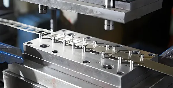
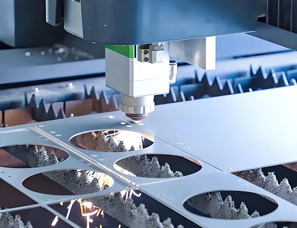
Sheet metal design for manufacturability (DFM) is the process of optimizing part geometry, material selection, tolerances and assembly features so a design can be manufactured consistently, economically and reliably. It considers laser cutting, CNC bending, punching, stamping, welding and surface finishing before production begins, rather than after a first article fails.
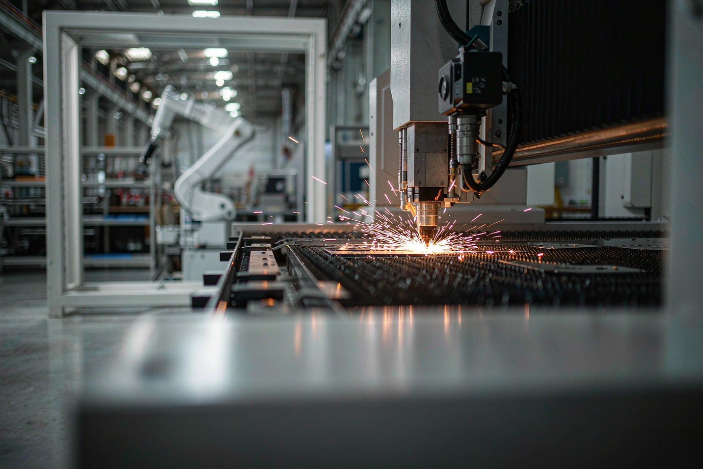
Xiamen Goldcattle provides custom sheet metal fabrication and engineering support for OEM customers. Our manufacturing capabilities include fiber laser cutting, CNC bending, stamping, punching, TIG/MIG welding, surface finishing and assembly. We review customer drawings to identify potential manufacturing, quality and cost issues before fabrication. DFM is not a checklist we hand over and forget — it is the engineering conversation that turns a drawing into a part that is practical to make.
The Sheet Metal DFM Checklist
The features an engineer actually checks are concrete: material and thickness, bend radius and flange length, hole and slot position relative to bends and edges, relief at corners, tolerance by function, weld access and sequence, fastener type and edge distance, and finish compatibility. The schematic below shows where these features sit on a typical bent part.
Material & Thickness Selection
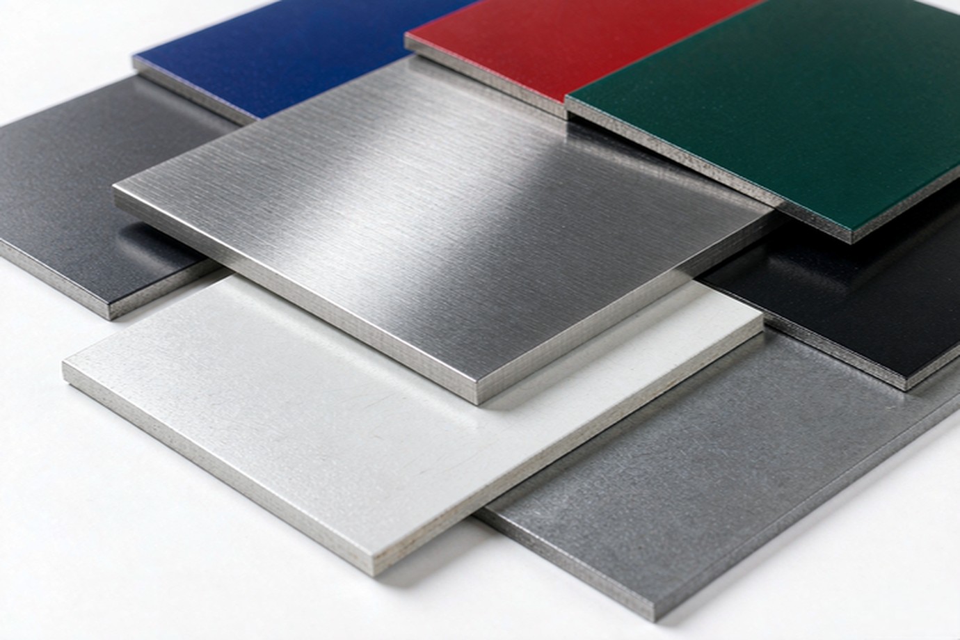
Material choice decides whether a design bends without cracking, welds cleanly, finishes well and stays affordable. We weigh strength and rigidity, ductility and formability, thickness and weight, material and processing cost, weld and finish compatibility, and supply stability for volume production.
| Material | Typical DFM consideration | Common application |
|---|---|---|
| Cold rolled steel | Forming, welding, corrosion protection | Enclosures, brackets |
| Stainless 304 | Ductility, springback, work hardening | Equipment housings |
| Stainless 316 | Corrosion resistance, forming and welding | Special-environment equipment |
| Aluminium 5052-H32 | Bend performance, springback, grain | Lightweight enclosures |
| Aluminium 6061-T6 | Larger bend radius, crack risk control | Structural brackets, mounts |
| Galvanized steel | Coating protection, weld and edge corrosion | Electrical enclosures |
Bend Radius, Bend Allowance & K-Factor
Bending is where most sheet metal DFM questions start. The inside radius, outside radius, bend allowance, bend deduction, K-factor, springback, grain direction and the air-bending versus bottoming choice all affect the flat pattern and the final part.
| Material | Initial design reference | What to watch |
|---|---|---|
| Mild steel | Around 1T | Depends on thickness and condition |
| Aluminium 5052-H32 | Around 1T | Check bend direction vs grain |
| Stainless 304 | Around 1 to 1.5T | Springback and work hardening |
| Aluminium 6061-T6 | Around 2 to 3T or more | Evaluate crack risk specifically |
T is the nominal material thickness. These are initial engineering references, not a fixed value for every part: material condition, thickness, rolling grain, die V-opening and bending method can all shift the practical minimum radius. The K-factor — the ratio of the neutral-axis distance to the inner surface, divided by the thickness — is similarly process- and material-dependent and is calibrated from bend trials rather than assumed constant.
Hole Placement & Feature Spacing
Hole-to-bend distance is one of the most searched sheet metal questions for good reason: a hole too close to a bend can elongate or distort as the material forms. The safe distance is measured from the hole edge to the bend tangent line.
| Design item | Initial reference | Purpose |
|---|---|---|
| Hole-to-bend distance | Around 2.5T + R | Reduce bend-induced hole distortion |
| Hole-to-edge distance | Around 2T from edge | Lower edge-tearing risk |
| Hole-to-hole spacing | Around 2T between edges | Keep enough material strength |
| Minimum hole diameter | Evaluated from about 1T (punching) | Avoid punch damage and quality issues |
| Slot width | Set by cutting method and thickness | Avoid unstable narrow-slot quality |
R is the inside bend radius. These are starting rules; the real distance is re-checked by material, thickness, cutting method, bending tooling and function. Laser cutting and mechanical punching are not held to the same minimum-hole rule, and we also review slots near bends, countersinks near edges, louvers and ventilation holes, cutouts near corners, and holes that span multiple bent surfaces.
Flange Length & Relief Design
Minimum flange length is not set by thickness alone — it is also governed by the die V-opening, punch, material, thickness and bending method. Too short a flange may not locate correctly, or may slip and deform during forming. As a starting range, minimum flange length is roughly 3T to 4T plus a process-dependent bend allowance; this is an early-design experience range, not a production guarantee for every machine.
Minimum Flange Height
Keep enough flange to locate and form the bend; short flanges risk slipping and distortion.
Bend & Corner Relief
Reliefs where a bend meets an edge or corner prevent tearing and let the material form cleanly.
Notch Geometry
Notch size and position affect both formability and the flat pattern; reviewed with the bend.
Hem Design
Hems add edge safety and stiffness; their radius and width are set by material and thickness.
Flat Pattern & CAD Design
A 3D model does not automatically unfold into an accurate flat pattern. If the designer's thickness, bend radius and K-factor differ from the shop's actual bending process, the blank will be off. After receiving your 3D CAD we re-check material, bend parameters and unfolding, then release the final flat data to laser cutting.
We review DXF preparation, bend lines, bend allowance, bend deduction, K-factor, corner compensation and grain direction together, and confirm the flat pattern against the fabrication process rather than copying model values blindly. This is where laser cutting and CNC bending capability connect directly to the drawing.
Tolerance & GD&T Design
Not every dimension should carry plus or minus 0.05 mm. Cutting, bending, welding and finishing each add variation — laser positional drift, thickness variation, bend-angle variation, springback, weld distortion and assembly variation all enter the size chain. Tolerances are set by function:
| Type | How to set it |
|---|---|
| Critical dimensions | Directly tied to fit and function — assign a defined tolerance |
| General dimensions | Set a reasonable shop capability, not an artificially tight value |
| Cosmetic surfaces | State surface, scratch, dent and coating requirements explicitly |
| Assembly interfaces | Control with common datums and position tolerances |
To reduce tolerance stack-up, a bracket with four bends should not locate a final hole through a chain of sequential bend dimensions. A better approach uses a common datum and GD&T by function, with assembly verification where needed. For US drawings, ASME Y14.5-2018 (R2024) defines dimensioning and geometric tolerancing; for general tolerances and geometrical specifications, ISO 22081:2021 is the current effective reference. General tolerances are defined according to the applicable drawing standard, customer requirements and functional interfaces — ISO and ASME are not treated as interchangeable.
Fastener, Welding & Assembly Design
Thin sheet may not give enough thread engagement for direct tapping; positions that are assembled and disassembled repeatedly can use self-clinching nuts, studs, rivet nuts or threaded inserts. When a design has many screw points, we review the insert hole size, required edge distance, tool access, thickness versus fastener range, pre- and post-finish dimensions, and serviceability.
For welding, design means selecting accessible joints, reasonable weld length and location, a sequence that controls distortion, and fixtures that hold the assembly. Where a large amount of continuous welding is specified, we review whether bends, hems or mechanical fastening can replace some welds without compromising strength, sealing or shielding — reducing distortion and rework. This connects directly to our TIG/MIG welding, welding fixtures and post-weld inspection.
Surface Finishing Design
Finishing is not just a list of options — the design affects whether the finish succeeds. We cover powder coating, anodizing, zinc plating, passivation, electropolishing, brushing and bead blasting, and the design points that matter: coating thickness allowance, masking areas, drainage and vent holes, weld-seam accessibility, cosmetic-surface protection and post-finishing assembly clearance.
Design for Cost Optimization
Cost is designed in. The levers are concrete and reviewable per project:
| Cost driver | DFM optimization | Value |
|---|---|---|
| Material usage | Optimize outline and nesting | Less scrap |
| Cutting time | Fewer unnecessary paths and tiny holes | Less laser time |
| Bending operations | Standardize radius and direction | Fewer setups |
| Welding | Optimize joint and weld length | Less labor and distortion |
| Tooling | Match laser, punch or dedicated tooling to volume | Right tooling investment |
| Finishing | Fewer unnecessary masks and complex surface specs | Lower finishing cost |
The savings are evaluated from the drawing, not quoted as a fixed percentage. A typical before-and-after shows a design with several separate parts, heavy welding, repeated fixturing and many assembly steps; the optimized version integrates bend structure and reduces unnecessary welding and assembly, improving repeatability. The exact material utilization, operation count and lead-time change are reported per project.
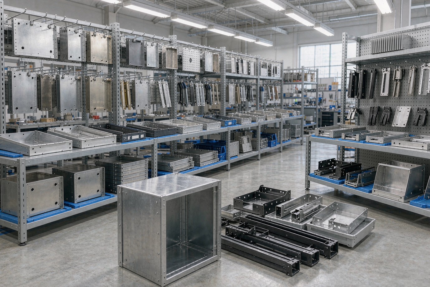
Goldcattle Sheet Metal DFM Review
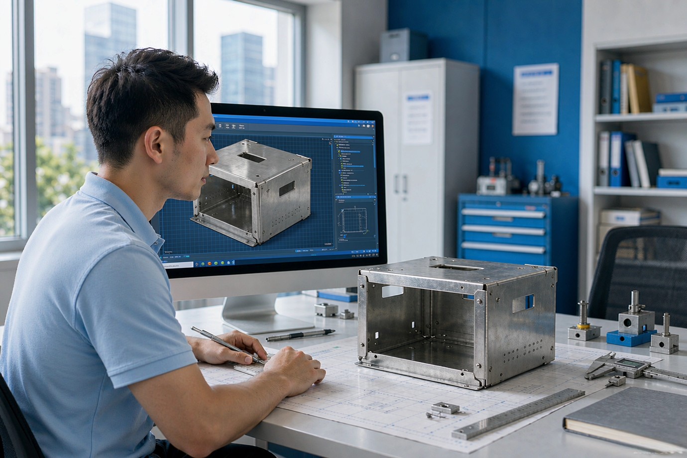
Submit your sheet metal CAD files and engineering drawings for a manufacturability review. Our engineering team evaluates material selection, bending geometry, feature spacing, tolerance requirements, joining methods and production considerations before fabrication. Reviews are carried out by our sheet metal manufacturing engineers (for example Engineer Zhang and the process team) and returned as a written DFM report.
| Review item | What we report |
|---|---|
| Material & thickness | Whether the material suits the function and volume |
| Geometry | Whether the structure is manufacturable |
| Bend design | Radius, flange and flat pattern soundness |
| Hole position | Distance to bends and edges |
| Tolerance | Fit to process and assembly |
| Welding | Joint, length and sequence |
| Hardware | PEM, nut, rivet feasibility |
| Finishing | Coating compatibility |
| Process route | Laser / punch / bend choice |
| Cost optimization | Unnecessary cost or operations |
Each finding is structured as Drawing Location → Identified Issue → Manufacturing Risk → Recommended Revision → Cost / Quality / Lead-time Impact, grouped into Critical (must fix), Major (should change), Optimization (can improve) and Accepted (currently fine). We respond to every inquiry within 24 hours; a full DFM review is returned after we receive a complete drawing package and review scope. Drawings are handled under NDA on request. For broader manufacturing capability see our manufacturing services page.
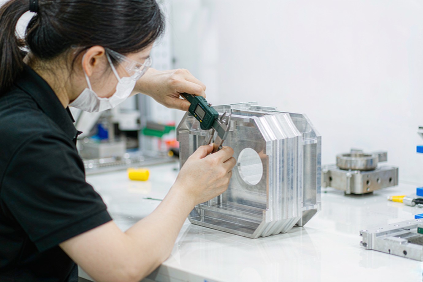
Representative DFM Case Study
Representative project — enclosure design optimization
A sheet metal enclosure arrived as several separate stamped and welded pieces with repeated fixturing and many assembly steps. The review flagged avoidable welding and a tolerance chain that risked stack-up at the final hole pattern.
- ApproachIntegrated bend structure to replace some welded joints; re-based critical holes on a common datum; standardized bend radius and direction.
- OutcomeFewer fabricated and assembled operations, improved repeatability and a clearer inspection plan. Exact savings are reported per project, not as a fixed figure.
This is a representative composite of projects we support, written without a named customer or fabricated measurements — specific results and references are shared under NDA.
FAQ
What is design for manufacturability in sheet metal?
What are the most important sheet metal DFM rules?
What is the recommended bend radius for sheet metal?
How far should holes be from a bend?
How can I reduce sheet metal fabrication costs?
How do tolerances affect sheet metal manufacturing?
What causes sheet metal bending cracks?
How do you design sheet metal parts for welding?
What files are required for a sheet metal DFM review?
Can a sheet metal manufacturer review my CAD drawing?
Submit Your CAD Drawing
What to send for a sheet metal DFM review
Required fields let us scope the review; optional fields sharpen it.
Note: drawings are handled under NDA on request. We respond within 24 hours and return a written DFM review after a complete drawing package is received. For supplier due diligence from a procurement perspective, see our how to verify a Chinese supplier guide.
Ready to review your sheet metal design?
Send the CAD and the drawing. We will return a manufacturability review and a cost and process observation scoped to your part — not a generic checklist. For the full fabrication scope, see our custom sheet metal fabrication services.
Request a DFM Review Explore sheet metal fabrication servicesXiamen Goldcattle Plastic & Metal Products Co., Ltd. — Founded in 1998 · ISO 9001:2015 certified · OEM/ODM build-to-print.