Prototype to Production Sheet Metal: One Supplier From First Sample to Scaled Volume
A practical look at how a custom sheet metal part moves from a single prototype to repeatable mass production — the processes, the DFM checks, the tolerances, and the quality gates that keep the part consistent the whole way.
At a glance
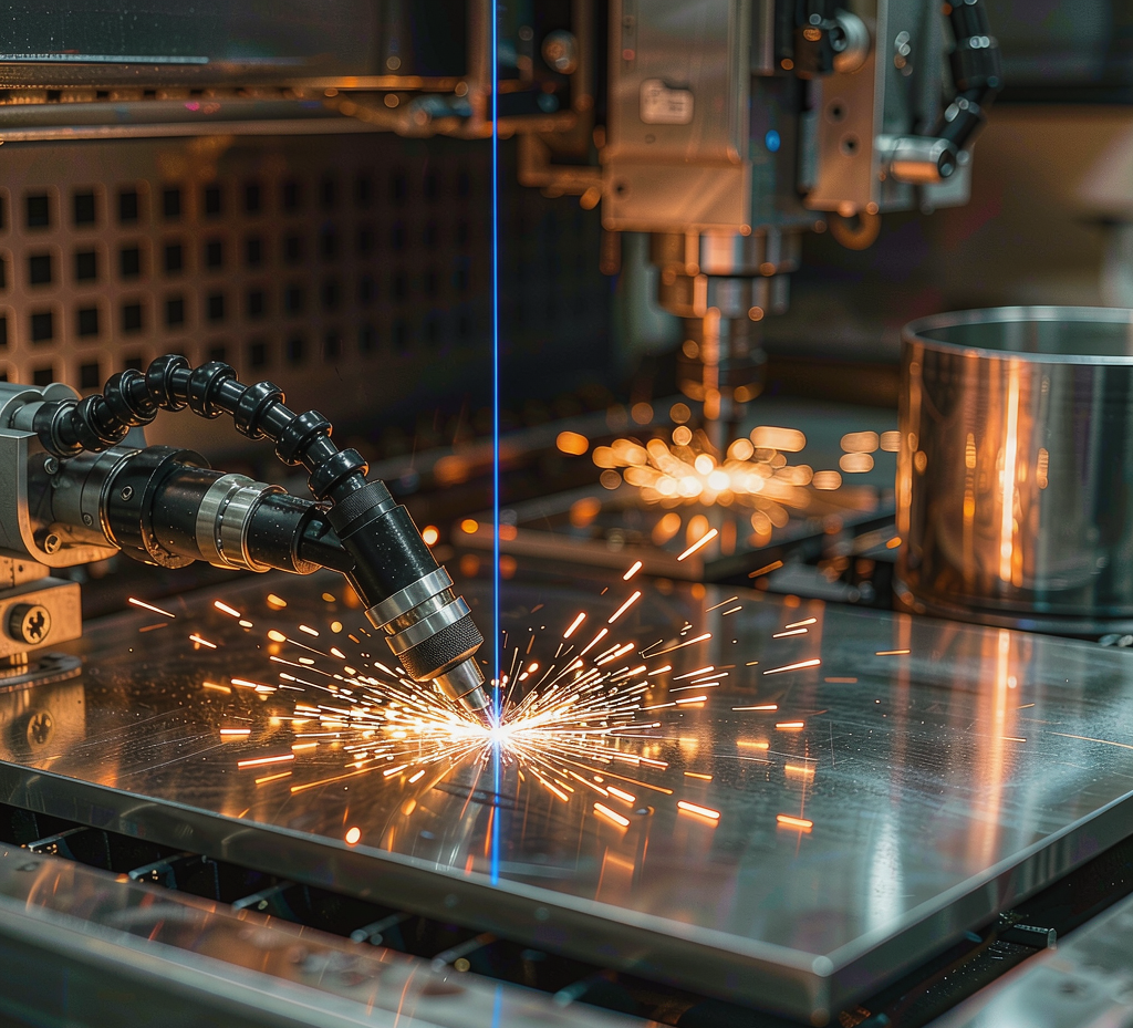
“Prototype to production sheet metal” means running the same part through one continuous pipeline — sample, design feedback, small-batch validation, then scaled volume — instead of re-sourcing at each step. The payoff is consistency: the part you approve as a prototype is the part you receive at volume, because the cutting, bending, welding, and inspection setup carry over unchanged.
Why buyers keep prototype and production with one shop
When the prototype and the production order sit with different suppliers, the production part rarely matches the sample — tooling, bend sequencing, and weld setup drift, and the first production batch becomes a second prototyping loop. Consolidating both stages removes that hand-off risk. Four points matter most to procurement and engineering teams:
One setup, same result
Cutting programs, bend schemas, and weld fixtures developed for the sample are reused in production, so dimensional behavior carries over instead of being re-derived.
DFM before cutting
A design-for-manufacture review happens on the first drawing, so expensive changes are made on paper rather than after parts are already bent and welded.
Verified at every stage
Incoming material checks, in-process inspection, and First Article Inspection let you confirm the production part against the approved sample before a full run.
From 1 piece to volume
The same line takes a single prototype and a recurring production order without re-quoting the manufacturing approach each time.
The 6-stage workflow
A custom sheet metal part does not jump from drawing to volume in one step. The path below is the same whether the order is one sample or ten thousand — only the depth of validation changes with volume.
First sample from drawing
A single part is cut and bent to prove the geometry. This is where fit, clearances, and assembly behavior are checked against the CAD intent.
Engineering feedback
Bend radii, hole-to-edge distances, weld access, and tolerance stack-up are reviewed. Minor geometry changes here prevent scrap later.
Confirmed prototype
After DFM adjustments, a revised sample is produced and approved. This approved part becomes the reference for all later inspection.
Low-volume validation
A short production run verifies repeatability, fixturing, and finishing at scale before committing to a full order.
FAI & sign-off
For higher volumes, a First Article Inspection report documents key dimensions against the control plan so production is released with confidence.
Repeatable volume
The validated setup runs the production quantity with in-process inspection, then ships against the agreed plan.
DFM review: what gets checked before cutting
Design-for-manufacture is where most sheet metal cost is won or lost. The review is a structured checklist, not a vague “we’ll see.” The items below are the ones that most often move a part from “hard to make” to “clean and repeatable.”
Match radius to thickness
An inside bend radius near the material thickness bends predictably. Radii far below the thickness crack; radii far above need special tooling. DFM sets the radius to the stock.
Keep distance from bends
Holes and slots placed too close to a bend distort when the flange forms. DFM shifts them into stable flat areas or adds relief.
Design for the torch
Weld joints need clearance for the gun and repeatable fixturing. DFM flags hidden or cramped joints and proposes accessible alternatives.
Confirm the chain
Cut, bend, and weld each add variation. DFM checks whether the specified tolerances survive the full process chain before any cutting begins.
Process by volume
The right process mix depends on how many parts you need and how fast. The same part can be made several ways; the table shows where each approach fits.
| Volume band | Typical approach | Lead time | Best for |
|---|---|---|---|
| Prototype (1 pc) | Laser cut + hand bend, DFM review | 3–7 working days | Fit checks, design validation |
| Low volume (tens to low hundreds) | Laser cut + press brake, spot/TIG weld | 7–20 working days | Pilot runs, pre-launch stock |
| Mass production (hundreds+) | Optimized nesting + repeat bending + FAI | 15–25 working days | Recurring supply, assembled units |
Lead times above start after DFM sign-off and assume standard materials and finishes. They are planning ranges, not a quotation — final schedule depends on part complexity and order volume.
Materials & finishes
Material choice drives weld behavior, corrosion resistance, and finishing options. The grades below are the ones most often specified for fabricated enclosures, brackets, and structural parts.
| Material | Common grades | Why specify it | Typical finishes |
|---|---|---|---|
| Mild steel | SPCC / CR | Low cost, easy to weld and form | Powder coat, zinc plate |
| Stainless steel | 304, 316 | Corrosion resistance, hygiene | Passivation, brushed, powder coat |
| Aluminum | 5052, 6061 | Light weight, good formability | Anodize, powder coat |
| Galvanized sheet | DX51D+Z | Pre-coated corrosion protection | as-supplied, touch-up paint |
For a broader material reference across our machining and fabrication work, see the materials overview. When a feature is better produced by machining than by forming, our CNC process guide covers process selection.
Quality & First Article Inspection
Quality is built into the run, not inspected in at the end. The control points below apply from the first sample through mass production.
Material verification
Stock is checked against the specified grade and thickness before it enters the cutting queue.
Control plan
Key dimensions are measured during the run so drift is caught before a full batch is produced.
FAI on request
A First Article Inspection report documents critical dimensions against the approved sample for production release.
Where these parts go
Fabricated sheet metal spans most industrial sectors. The list below reflects the application areas typically served.
Electrical & control
Panels, boxes, and racks for equipment housings.
Automotive & transport
Brackets, mounts, and structural plates.
Industrial equipment
Frames, guards, and machine covers.
Device structures
Cleanable enclosures and supports.
Chassis & shielding
Housings and EMI-sensitive parts.
Appliance & fixture
Formed panels and retail fixtures.
A typical project path (illustrative)
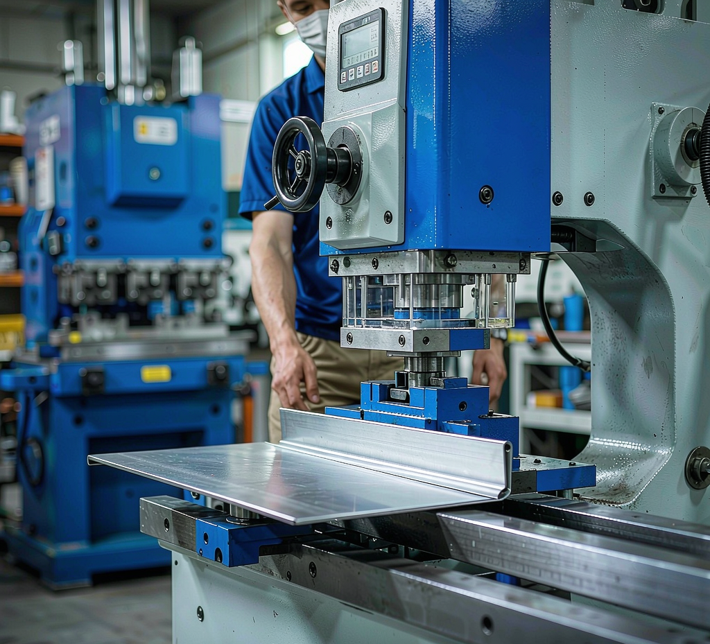
The timeline below shows how a generic fabricated bracket moves through the pipeline. It is a representative flow to illustrate staging — every real project is quoted against its own drawing, volumes, and finish.
| Step | Activity | Output |
|---|---|---|
| 1 | Drawing received, DFM review | Feasibility + change notes |
| 2 | Prototype cut & bent | First sample (≈3–7 d) |
| 3 | Sample approved | Reference part for inspection |
| 4 | Small-batch trial | Repeatability confirmed |
| 5 | FAI + production release | Signed control plan |
| 6 | Mass production & ship | Volume order (≈15–25 d) |
Cost & lead-time drivers
Two questions dominate every RFQ: “how much” and “how fast.” Both are driven by a small set of variables that are worth understanding before you send the drawing.
Complexity of form
More bends, tighter radii, and welded assemblies add setup and handling time beyond simple flat cut parts.
Grade & thickness
Stainless and thicker stock cut and form differently than mild steel, affecting both tooling and cycle time.
Coating & treatment
Powder coat, anodize, or plating add a downstream step with its own queue outside the fabrication cell.
Order quantity
Higher quantities amortize setup across more parts, but scheduling and material lead time scale with the run.
Send a drawing, get a DFM-oriented quote
Share your STEP, IGES, DWG, or PDF with material, quantity range, and finish. We return lead time and a prototype plan — and the same setup carries through to production.
Request a Quote Browse all manufacturing services →One supplier from first sample to scaled volume · DFM review included on every new part.
Frequently asked questions
What does "prototype to production sheet metal" mean for a custom order?
What lead times can I expect on a custom sheet metal order?
Which sheet metal processes are used?
What tolerances are achievable on sheet metal parts?
Which sheet metal materials can you fabricate?
Do you provide DFM feedback before production starts?
What quality controls apply to production parts?
How do I start a sheet metal quote?
Ready to move from sample to volume?
Open the quote form, attach your drawing, and note the quantity range. We will come back with DFM feedback and a prototype plan.
Start Your QuotePrototype 3–7 working days · Mass production 15–25 working days · Minimum 1 piece.