Custom cams, cam followers, roller followers, track rollers and camshafts manufactured to your drawings, samples or application requirements. We build the geometry, heat treatment and inspection around how the part actually moves and loads.
Cam follower cutaway: outer ring rides the track, needle rollers carry the radial load, stud or yoke fixes the mounting.
We do not sell off-the-shelf catalog part numbers. Each cam, follower or roller is built to a drawing, sample or defined motion requirement.
Disc cams, plate cams, cylindrical and barrel cams, and other custom profiles machined to a specified lift and motion law.
Stud-type and yoke-type roller configurations with cylindrical or spherical outer rings, seal and lubrication options.
Cylindrical or crowned rolling elements sized to the track geometry, contact width and expected misalignment.
Machined shafts integrating one or more cam profiles, with journals and mounting features.
Cam plus roller or follower pairs built to defined contact conditions where the interface matters.
Reverse-engineered replacements from worn or discontinued samples where no current drawing exists.
These names are sometimes used interchangeably. For a quotation it helps to know which role the part actually plays.
| Component | Primary job | Typical interface |
|---|---|---|
| Cam | Converts rotary motion into a defined follower motion | Contacts the follower roller |
| Cam Follower | Rolling element that follows a cam or track while carrying radial load | Bears against cam or track |
| Roller Follower | Rolling guidance against a cam plate or track | Track surface |
| Track Roller | Supports guided linear or rotary motion along a track | Raceway / track |
A cam is defined by how the follower moves, not by a single material or hardness number. The geometry below drives both the design and the machining route.
The rise-dwell-return schedule the follower must follow: uniform, harmonic, cycloidal or a modified profile chosen for acceleration and noise.
The smallest radius of the cam. It sets the starting geometry and influences overall size and pressure angle.
Maximum follower displacement from the base circle. Rise, dwell and return angles define the timing.
The angle between the normal to the profile and the follower travel. A high angle raises side thrust and can destabilize the follower.
The roller radius must be compatible with the profile curvature to avoid undercutting and excessive contact stress.
The local radius of curvature controls contact stress, roller diameter choice and finish requirements.
Send these parameters with your drawing or sample. They determine the geometry, internal arrangement, seal and material route.
| Feature | Cylindrical outer ring | Spherical outer ring |
|---|---|---|
| Contact | Larger, well-defined contact line | Better accommodation of angular conditions |
| Typical use | Rigid, precisely aligned track | Misalignment-sensitive installations |
| Track condition | Requires controlled alignment | Can tolerate some mounting misalignment |
| Selection driver | Load and track geometry | Load plus installation condition |
A cam follower cannot be chosen by bearing dimensions alone. The mating track or cam surface sets the real load capacity and wear behavior.
Track material and hardness, surface finish, contact width, load distribution, alignment and lubrication. A soft track can wear out even when the follower itself is rated for the load.
If you are replacing an existing follower, tell us the track material and any visible wear pattern. That changes the recommended outer ring geometry and surface treatment.
Material choice follows the contact condition, speed and environment rather than a fixed matrix.
| Material category | Typical reason |
|---|---|
| Bearing / bearing steel | Rolling-contact components where hardness and wear govern life |
| Alloy steel | Camshafts, studs and structural sections |
| Stainless steel | Corrosion-sensitive or wash-down applications |
| Hardened / tool steel | Profiles subject to repeated sliding or rolling contact |
| Other engineering materials | Application-specific, evaluated case by case |
Heat treatment (quench and temper, carburizing, nitriding, surface hardening) is selected by material, contact load and wear requirement. Post-treatment grinding or finish machining compensates for dimensional change. * Specific steel grades depend on your drawing and application.
| Aspect | CNC machining | Profile grinding |
|---|---|---|
| Prototype | Strong fit | Setup-dependent |
| Complex geometry | Strong | Depends on grinding setup |
| Hardened material | Limited | Preferred after hardening |
| Fine profile finish | Good | Often preferred where specified |
| Setup cost | Generally lower | Higher setup and tooling consideration |
The right finishing process depends on material hardness, geometry, profile tolerance, required surface finish and production volume. We choose the route during process planning, not by default.
Profile geometry, lift, phase angle, bore diameter, concentricity, runout, flatness and surface roughness.
Outer diameter, stud or bore diameter, width, roundness, cylindricity, runout and surface finish.
Rotation, clearance, contact condition, alignment and functional movement where a matched set is supplied.
Inspection uses CMM and gauging methods suited to the drawing. Tight tolerances are assigned to functional features, not applied across every dimension.
Standard catalog parts cover many applications. Custom manufacturing is usually worth it when:
- Standard dimensions do not fit the machine
- Stud length or mounting interface is non-standard
- Roller profile is shaped for a specific track
- Material must be changed for the environment
- Seal or lubrication configuration is non-standard
- An existing component is obsolete or discontinued
- A replacement must match an old sample
- Multiple parts need matched dimensions
Indexing mechanisms, transfer systems, automated assembly, tool and pallet changers.
Cam-driven indexing, filling, labeling and conveyor mechanisms.
Track systems, conveyors and linear motion guidance.
Tool changing mechanisms, rotary positioning and dedicated machinery.
Custom motion mechanisms, replacement components and obsolete parts.
Reviewed case by case against load, speed and environment.
- 2D drawing or 3D model
- Cam type and motion diagram
- Base circle, lift, rise / return angles
- Speed, load, shock load
- Material, heat treatment, surface finish
- Quantity
- Drawing or sample
- Outer diameter, width, stud size
- Load, speed and expected life
- Track material and geometry
- Seal / lubrication requirement
- Material and quantity
Don't have a complete drawing? Send the available dimensions, sample photos and application parameters. We review what is missing and tell you what else is needed before we quote.
We build from 2D drawings, 3D CAD, existing samples or defined motion requirements.
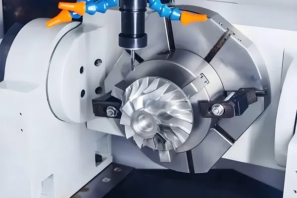
Milling, turning and multitask machining for cams, shafts and complex profiles.
Critical dimensions, profile features and runout checked against the drawing.
First-part validation followed by repeat or batch production.
Process, heat treatment and inspection planned before machining starts.
Materials selected for load, wear and environment.
What is a cam follower?
A rolling-contact component that follows the contour of a cam or track while carrying a radial load, typically built as a needle roller bearing inside an outer ring on a stud or yoke.
What is the difference between a cam follower and a roller follower?
The terms overlap. A cam follower usually means a stud or yoke style riding on a cam; a roller follower often means the rolling element directly contacting the cam profile. The correct name depends on the machine and mounting.
Can you manufacture a cam from a sample?
Yes. Where no drawing exists, we document the sample, review the mating parts and reverse-engineer the profile before production.
What information is needed for a custom cam?
A drawing or CAD model, cam type, base circle, lift, motion law, speed, load, material, heat treatment, surface finish, critical tolerances and quantity.
How do I specify a cam profile?
Define the rise-dwell-return motion law, base circle, maximum lift, rise and return angles, roller diameter and follower offset. A motion diagram or sample helps validate the geometry.
Cylindrical or spherical outer ring — which one?
Cylindrical for a rigid, well-aligned track. Spherical when some angular misalignment must be accommodated.
How is cam follower load capacity determined?
By bearing arrangement, outer ring material and hardness, track material and hardness, speed, shock load, lubrication and required life.
Does the track material affect performance?
Yes. Track hardness, finish and contact width affect contact stress and wear. A soft track can wear out even with a rated follower.
Can cam components be heat treated?
Yes. Quench and temper, carburizing, nitriding and surface hardening are chosen by material and duty. Finish machining or grinding after treatment compensates for dimensional change.
Can you supply the cam and follower as a matched set?
Yes. Where the contact interface is critical, we manufacture both parts to defined mating conditions.
Can you make obsolete or discontinued parts?
Yes. Send the sample and mating-component information; we review feasibility and propose a manufacturing route.
Send your drawing, 3D model, sample or application parameters. Useful inputs: part drawing, cam profile or motion diagram, material, load, speed, critical dimensions, heat treatment and quantity.