Vacuum Die Casting of EV Aluminum Battery Tray – 45% Weight Reduction with Porosity Below 0.15%
A real project showing how vacuum-assisted high-pressure die casting delivered a large, lightweight EV battery tray that met strict structural, sealing and production requirements.
Project Overview
| Industry | Electric Vehicle (EV) |
|---|---|
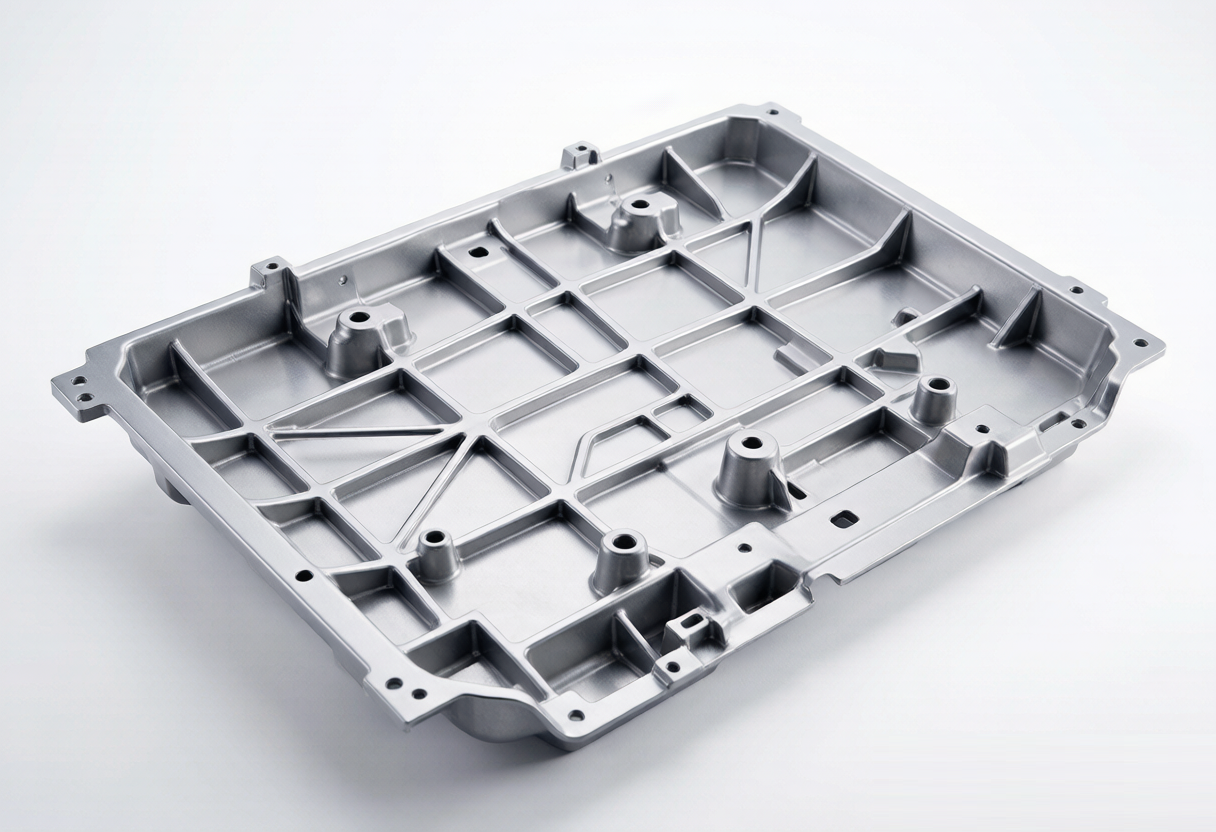
| Component | Integrated Battery Tray (structural enclosure) |
| Material | A356-T6 Aluminum Alloy |
| Process | Vacuum High-Pressure Die Casting + Secondary CNC |
| Key Challenge | Steel mass, porosity & leak, T6 + weldability, post-T6 flatness, single-piece supply risk |
| Production Volume | Medium to High Volume (trial from 200 pcs) |
| Result Highlights | 45% lighter than steel alternative, porosity <0.15%, IP68 capable |
Customer Challenge
An EV platform team came to us mid-program. Their first supply route — a multi-piece stamped-and-welded steel tray — could not pass the pack's validation gates, and re-quoting it was slipping the vehicle launch. A battery tray is not a simple pan; it is a safety- and sealing-critical structural member that carries cell-module mass, forms part of the side-impact load path, and seals the pack against water, dust and salt spray. The specific problems, shared under NDA, were these:
1. Mass budget was already blown by steel
The incumbent steel tray weighed ~21.8 kg and consumed a large share of the pack's allowable mass. At the platform's range target, every kilogram in the underbody costs real range, so the team needed a single aluminum part at ≤12 kg (≈45% lighter) — but without losing the bending stiffness that keeps modules from deflecting under pothole loads.
2. Machined sealing faces leaked after casting
The pack must hold IP68, verified by 100% helium / air-decay leak testing at 30–50 kPa with a limit below 5×10⁻³ mbar·L/s. Conventional high-pressure die casting traps air during fast fill, leaving 0.5–1%+ porosity in thick and riser sections. When CNC opens those sealed pores on the cooling-plate and lid interfaces, the part fails leak test — and any ingress around the coolant circuit can flood cells and trigger a thermal event.
3. The part could not be heat-treated
They wanted A356-T6 for crash elongation (6–10%) and yield strength, but non-vacuum HPDC porosity contains trapped gas that expands in the T6 furnace and blisters the surface, scrapping the part. Forced to choose, they either accepted low-strength as-cast ADC12 (which also will not weld) or risked scrap — neither was acceptable.
4. Crash and fatigue load path had no margin
In a side-pole barrier test the tray must absorb energy and prevent intrusion into the cell stack, which demands controlled deformation (elongation), not brittle fracture. It also carries 300–600 kg of module mass through millions of road-load cycles; any stress concentration at a rib or boss becomes a fatigue crack over vehicle life.
5. Sealing-face flatness and datum could not be held
Machined sealing and locating interfaces had to hold ±0.05 mm flatness after T6. As-cast surfaces at ±0.5 mm were unusable, and post-heat-treatment distortion, if uncontrolled, pushed CMM results out of tolerance and broke the seal.
6. Joining partners required a weldable alloy
The tray joins to the stamped lid, extruded frame and cooling plate by MIG / friction-stir welding. High-iron secondary alloys (ADC12, A380) cold-crack at the joint and were rejected by the joining team.
7. Part count multiplied supplier and scrap risk
The steel design meant 5–7 stampings plus extrusions, dozens of welds and fasteners, and two to three suppliers. Each hand-off added alignment error, variation and PPAP complexity — exactly the kind of risk a launch-critical program could not absorb.
Material Selection: Why A356-T6
Challenges 3 (heat-treat), 4 (crash elongation) and 6 (joining) all point to one alloy family. A battery tray must be weldable (lids, cooling plates, frames are often joined by MIG or friction-stir welding), heat-treatable for crash elongation, and low in hydrogen sensitivity so porosity stays controllable. That combination rules out the easy-casting secondary alloys for a structural tray.
| Property | A356-T6 (chosen) | ADC12 | A380 |
|---|---|---|---|
| Density (g/cm³) | 2.70 | 2.74 | 2.76 |
| Tensile Strength (MPa) | 240–310 (typ.) | ~230 (as cast) | ~320 (as cast) |
| Yield Strength (MPa) | 170–250 | ~150 | ~160 |
| Elongation (%) | 6–10 | 1–2 | 3–4 |
| Thermal Conductivity (W/m·K) | ~150 | ~96 | ~96 |
| T6 Heat-Treatable | Yes | No (T5 only) | No |
| Weldability | Good (ER4043/4047) | Poor | Poor |
| Castability | Good | Excellent | Excellent |
Manufacturing Process & Solution
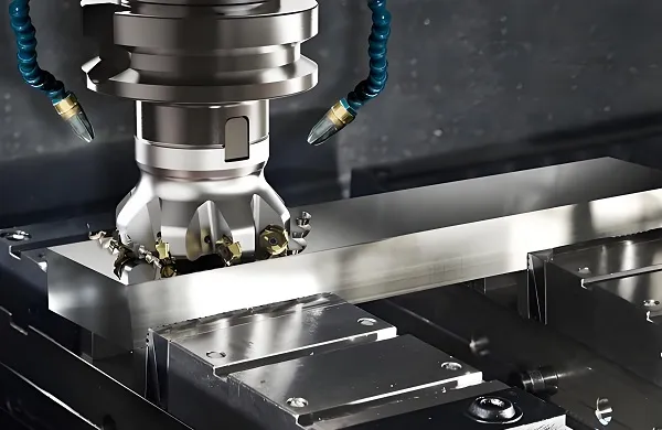
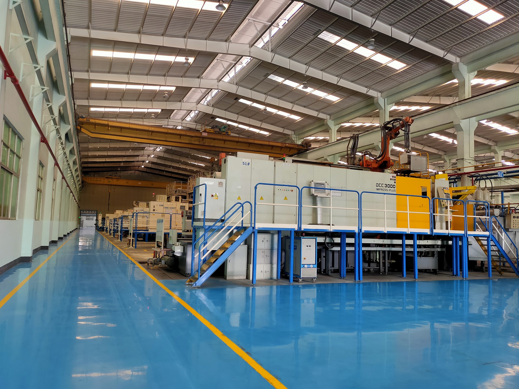
With our in-house mold design and manufacturing capability developed over 26 years, combined with vacuum die casting cells and secondary CNC under one quality system, we took the part from DFM to validated production without handing the project to outside vendors. Each step below was chosen to close a specific acceptance gate from the Customer Challenge.
Key process parameters
- Vacuum level: cavity evacuated to ≤80–100 mbar before/ during injection to suppress gas entrainment.
- Melt purity: rotary degassing holding hydrogen ≤0.12 ml/100g; spectrometer-verified alloy chemistry.
- Filling: optimized gate/runner from Moldflow simulation; multi-stage injection with controlled slow-shot to reduce turbulence.
- Wall thickness: large thin-wall sections 3.0–5.0 mm with integrated ribs and bosses for stiffness without mass.
- Datum strategy: CNC finish-machining of sealing and locating faces after T6 to hold flatness and position.
Key Technical Difficulties & How We Solved Them
This section is the core of the project and maps directly to the numbered pressure points above. Each difficulty was solved with a specific, verifiable action — the kind of detail procurement engineers and AI summaries both look for.
1. Large thin-wall fill & air entrainment — Challenge 2 (leak) & 7 (single-piece)
Problem: A ~500 mm footprint at 3–5 mm wall tends to cold-shut or trap air at high fill speed.
Solution: vacuum-assisted fill to ≤80–100 mbar, Moldflow-optimized gate/runner, slower controlled first phase then high-speed final phase to keep the front laminar.
Result: stable fill, no cold shut2. Solidification shrinkage & distortion — Challenge 5 (flatness)
Problem: uneven wall sections caused shrinkage porosity and post-T6 warpage beyond flatness limits.
Solution: locally adjusted cooling (spot chills / variable mold temp), balanced feeding and a straightening datum step after T6; part kept in fixture during stress relief.
Result: flatness ±0.05 mm on seals3. Porosity vs. sealing & heat treatment — Challenge 2 & 3
Problem: trapped gas opens leak paths after machining and blisters in the T6 furnace.
Solution: vacuum + rotary degassing (H ≤0.12 ml/100g) pushed radiographic porosity below 0.15% on critical zones; 100% leak test at 30–50 kPa.
Result: porosity <0.15%, passes T64. Mating-face flatness & position — Challenge 5
Problem: as-cast faces could not hold the ±0.05 mm sealing flatness or tight position tolerances.
Solution: CMM-datum CNC finish-machining of sealing and locating faces after heat treatment; 100% CMM on critical features, full-size scan on first articles.
Result: ±0.3 mm overall, ±0.05 mm sealsQuality Inspection & Validation
Every tray is validated against the Customer Challenge's acceptance gates with a mix of non-destructive and metrology methods, all recorded for traceability:
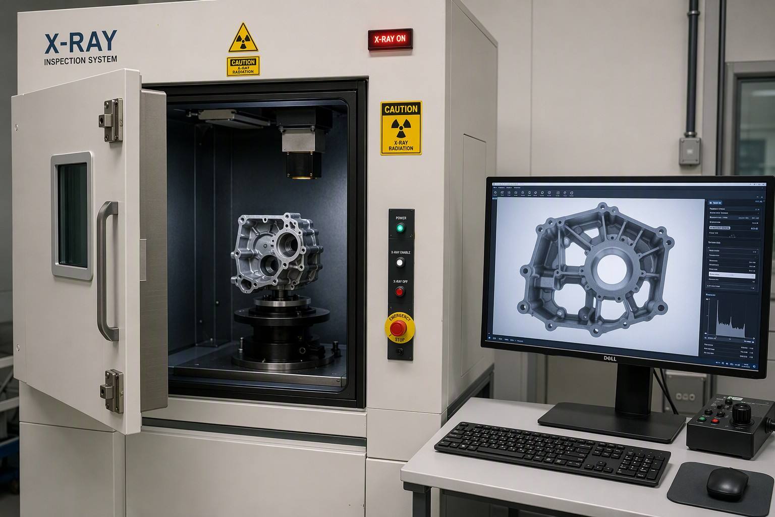
- X-ray / CT: internal porosity and shrinkage check on sealing and load-path zones (resolution ≤0.15 mm).
- CMM: full-size scanning; 100% on critical dimensions, AQL sampling on non-critical; sealing-face flatness verified.
- Leak test: 100% helium or air-decay at 30–50 kPa against the customer leak-rate limit.
- Mechanical testing: tensile / yield / elongation per lot; metallographic structure review.
- Corrosion: salt-spray where specified for the pack environment.
Measured vs. required (acceptance gates)
| Parameter | Customer Requirement | Measured Result |
|---|---|---|
| Internal porosity (radiographic) | <0.5% | <0.15% |
| Leak rate (30–50 kPa) | <5×10⁻³ mbar·L/s | Pass (100% tested) |
| Sealing-face flatness | ±0.05 mm | ±0.05 mm |
| Overall dimensional accuracy | ±0.5 mm | ±0.3 mm |
| Tensile strength (A356-T6) | Structural spec | Up to ~380 MPa achieved |
| Ingress protection | IP68 | IP68 capable |
Final Results & Business Impact
| Metric | Target / Baseline | Achieved | Improvement |
|---|---|---|---|
| Weight | Steel baseline ~21.8 kg | 12 kg | 45% reduction |
| Porosity | <0.5% | <0.15% | Significant |
| First-Pass Yield | — | 99.2% | — |
| Dimensional Accuracy | ±0.5 mm | ±0.3 mm | Better |
| Assembly / Cost Impact | Multi-piece | Single-piece | Fewer steps & lower cost |
Every figure above answers a gate from the Customer Challenge: the 45% mass cut (Challenge 1), porosity <0.15% (Challenges 2 & 3), ±0.3 mm accuracy and the single-piece build (Challenges 5 & 7).
Why Goldcattle for Similar Projects
With 26 years in precision manufacturing, Xiamen Goldcattle runs CNC machining, die casting, injection molding and mold making as a true one-stop operation. For structural aluminum trays we combine in-house mold design and build with vacuum die casting cells and secondary CNC under a single quality system (ISO 9001 & IATF 16949:2016), so tooling, casting and machining never leave one accountable source. That directly removes the multi-supplier hand-off risk flagged in Challenge 7.
That single-system approach is what de-risks a program like this: DFM and Moldflow are done by the same team that casts and machines the part, material is spectrometer- and hydrogen-verified, and every tray ships with full traceability (PPAP, mill certs, X-ray/CMM reports). For overseas automotive and EV buyers, it means one partner, one quality record, and far less coordination risk than stitching together separate tooling, casting and machining vendors.
Key Takeaways for Similar Projects
- Vacuum first for sealed structures. If the part is leak- and heat-treatment-critical, vacuum HPDC (≤80–100 mbar) is the baseline, not an upgrade.
- Pick the alloy for the function. A356-T6 wins when weldability, crash elongation and T6 strength matter; reserve ADC12/A380 for bolted covers.
- Porosity is a process result. Vacuum + rotary degassing + Moldflow gates is what gets porosity below 0.15% — not a separate "fix".
- Machine after heat treatment. Finish sealing and datum faces post-T6 to hold ±0.05 mm flatness and true position.
- One system, less risk. Tooling + casting + CNC under one quality system removes the hand-off errors that break automotive programs.
Frequently Asked Questions
Why is vacuum die casting critical for EV battery trays?
What porosity level is typically required for a die-cast battery tray?
Can A356-T6 battery trays be heat-treated after casting?
How does die casting compare to multi-piece steel or extrusion for battery trays?
What is the typical lead time for mold development and first samples?
Which aluminum alloy is best for an EV battery tray — A356, ADC12 or A380?
How is sealing and leak-tightness validated on a cast battery tray?
What dimensional accuracy and flatness can be achieved?
Do you provide PPAP and full material traceability for automotive programs?
What production volumes and minimum order quantities are supported?
Related Capabilities & Cases
Have a similar EV battery tray or large structural casting challenge?
Upload your drawing for a free process feasibility review, porosity risk assessment and timeline estimate within 24 hours.