Process selection guide · multi-material molding
Insert Molding vs. Overmolding: How to Choose the Right Process
These two processes answer different questions. Insert molding exists to put a preformed component — a threaded insert, bushing, pin or terminal — inside the plastic part, positioned and held. Overmolding exists to put a second material over a substrate so the part gains a function: grip, sealing, cushioning or protection. Choosing between them is not a matter of which is better, but of which question your part is actually asking.
At a Glance
Two usages of “overmolding” — worth settling before you compare quotations.
In the narrow sense, overmolding means loading a preformed or supplied substrate into a second mold cavity and injecting a second material over it. On this reading, overmolding and two-shot molding are different routes with different tooling architectures.
In the broad sense, overmolding covers any process that applies a second material over a substrate, which includes two-shot molding as one way of achieving it.
This page uses the narrow sense, because that is what a buyer actually has to choose between. The disagreement you may see between suppliers is usually about which sense is in use, not about the process itself. If both materials are molded in one cycle inside one tooling system, you are looking at two-shot molding — see two-shot (2K) injection molding. If a substrate is loaded into a second cavity, that is overmolding — see overmolding services.
The Quick Answer
Short answer: insert molding is chosen for what has to be inside the part; overmolding is chosen for what has to be added over it. If your requirement is a fastening point, a wear surface, an electrical contact or a locally reinforced area, start with insert molding. If your requirement is a soft or sealing surface, a different colour or texture, or a cushioning layer, start with overmolding. If you need both, the question becomes how to sequence them.
Four things decide the answer, and cost is only the last of them:
- Function — what the finished part must do that a single-material molding cannot.
- Interface — whether a preformed component must be held against load, or two materials must stay bonded to each other.
- Tooling architecture — one cavity, two cavities, or one tool with two injection systems.
- Volume — whether the accumulated quantity justifies the tooling and automation the route needs.
Route by function, not by process name
Start from the requirement in the left column. The right column is what will actually decide whether the route works.
| What the part must do | Route to evaluate first | What decides whether it works |
|---|---|---|
| Provide a repeatable threaded fastening point, or hold a bushing, pin or shaft | Insert molding | Insert geometry and its mechanical locking features; insert location in the tool; wall thickness around the insert; pull-out and torque performance. |
| Terminate or connect electrically — a terminal, contact or small board | Insert molding | Positional tolerance of the conductor, encapsulation integrity in service, and whether the insert can be loaded without damage. |
| Reinforce or armour a local area where the plastic alone is too soft or too thin | Insert molding | Whether the metal carries load or only resists wear; how the load path transfers into the surrounding polymer. |
| Provide grip, soft-touch, anti-slip or ergonomic feel | Overmolding | The substrate grade and the overmold grade as a specific pair; whether the bond is chemical, mechanical or both. |
| Seal, gasket, cushion or damp vibration | Overmolding | The interface geometry as a sealing feature; compression behaviour of the elastomer; where the material boundary sits. |
| Add a second colour, texture or cosmetic edge | Overmolding | Boundary definition and appearance acceptance; whether the look can be held across a production run. |
| Do both — an encapsulated component and a functional second material | Combined route | The sequence, the number of operations, and whether a multi-material tool is justified at your volume. |
| Nothing above, at low volume, or the design is still moving | Single material plus assembly | Accumulated cost of tooling, inserts, assembly labour and inspection against the cost of a more complex tool. |
Two clarifications that prevent most wasted engineering time. First, a metal component placed in a mold is not automatically a reliable joint — retention comes from the insert's shape and the plastic that locks around it, not from the fact that metal is present. Second, two materials from the same polymer family are not automatically compatible as grades — compatibility has to be checked for the exact grades, and where it cannot be confirmed, mechanical interlock is designed in.
What Each Process Actually Does
Short answer: both processes put two things into one part, but they put them there differently — and that difference is what drives tooling, cost and what you have to validate.
Insert molding: a component becomes part of the molding
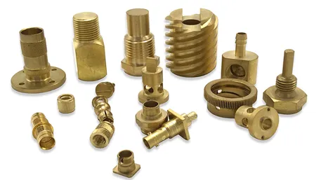
A preformed component is loaded into the mold and the polymer is injected around it, so the finished part is one piece instead of two. Retention is mechanical: the insert is held by knurling, grooves, flats or an undercut collar that the shrinking polymer grips as it cools, and sometimes by a mechanical interlock formed by the tool itself. That is why insert geometry matters more than insert material. The component can be metal — brass or steel threads, bushings, pins — but it can equally be a preformed plastic part, a composite, a ceramic or an electrical component such as a terminal or a small board.
The engineering question is not “can we put metal in the mold”, but whether the insert can be loaded repeatably, held at the right position through injection pressure, and locked well enough to carry the load the application puts on it.
Overmolding: a second material becomes a function
A substrate is placed into a second mold cavity and a second material is injected over it, so the finished part gains a surface property the substrate did not have. The bond usually comes from a combination of chemical compatibility between the two materials and mechanical interlock designed into the geometry — dovetails, holes, ribs or an undercut boundary that the overmold material flows into and grips. The substrate may be molded first in the same programme, or supplied as a bought-in part.
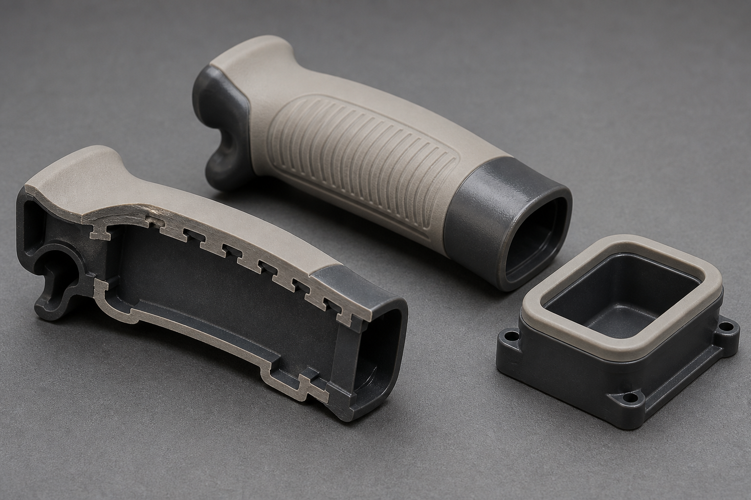
For the depth on either route as a service — material pairs, hardness ranges, surface preparation, defect modes and inspection methods — read overmolding services and two-shot (2K) injection molding. This page does not repeat them; it deals with the choice between them.
When to Use Insert Molding
Short answer: when something that is not plastic has to be in a specific place inside the part, and the part is better as one piece than as two assembled pieces.
| Requirement | Why insert molding fits | What to check before you commit |
|---|---|---|
| A plastic housing needs a threaded point that will be assembled and disassembled repeatedly | A molded thread in plastic wears out under repeated use; a metal thread does not. | Insert type and its locking features; the wall thickness and boss diameter around it; the torque the assembly operation will apply. |
| A connector or housing must carry a terminal, contact or small board in a fixed position | The insert is located by the tool rather than by a later assembly operation, which removes a positioning step and its tolerance stack. | Positional tolerance of the conductor, and whether it can be loaded into the tool without damage. |
| A locally loaded area needs metal a plastic alone cannot provide | The reinforcement is placed exactly where the load path is, without joining two parts. | Whether the insert carries load or only resists wear, because that changes how the surrounding polymer must be designed. |
| An assembly step should be eliminated to remove labour and its defect risk | The integration happens in the molding cycle rather than at a bench. | Whether the insert loading itself can be automated at your volume, or becomes a manual station with its own error rate. |
Placing metal in a mold does not create a reliable joint. Retention comes from the insert's mechanical features, the plastic that locks around them and how the part is loaded in service. An insert with a smooth cylindrical wall, a boss that is too thin, or a load applied across the parting line will move, spin or crack the surrounding polymer — and it will do so after approval, on parts that passed dimensional inspection.
When to Use Overmolding
Short answer: when the part needs a surface that behaves differently from the body of the part.
| Requirement | Why overmolding fits | What to check before you commit |
|---|---|---|
| A tool, handle or enclosure needs grip or a soft-touch surface | The elastomer is molded exactly where the hand goes, with a texture that molding can produce directly. | The substrate grade and elastomer grade as a specific pair, not as families; the boundary line; the overmold wall thickness. |
| The part must seal against another surface or keep contamination out | The seal becomes a molded feature of the part instead of a separate gasket to be fitted. | Whether the interface geometry actually forms the sealing feature, and how the elastomer behaves under compression in service. |
| The part needs cushioning, impact absorption or vibration damping | A compliant layer can be placed only where it is needed. | Service temperature and chemical exposure, which can change the elastomer's behaviour more than its hardness suggests. |
| The product needs a second colour, a different texture or a cosmetic edge | Colour and texture come from the tooling, without a painting or printing step. | How the boundary will be defined and accepted, and whether that appearance can be held across a production run rather than on a sample. |
Two materials from the same family are not automatically a working pair. Compatibility must be confirmed for the exact grades you intend to use, not inferred from names like “ABS” or “TPE”. Where chemical bonding cannot be confirmed, mechanical interlock is designed into the interface, and the result is confirmed on samples rather than assumed from a data sheet.
When You Need Both
Short answer: a part can need an encapsulated component and a functional second material at the same time. That is not a choice between insert molding and overmolding — it is a question of how to sequence them and what tooling that requires.
Typical examples include an enclosure with a metal threaded point and a soft sealing rim; a device with a connector body and a soft-touch outer surface; or a housing that must carry a metal wear surface and an elastomer gasket in the same part. The engineering tasks that have to be settled are:
- How many materials are involved, and what function each one carries. A material that carries no function is a cost with no benefit.
- Where the preformed components are located, and whether they can be loaded into the tool in the sequence the process requires.
- Which interfaces need mechanical fixing and which need a reliable material bond — they are validated by different tests and fail in different ways.
- Whether the operations can be automated, and what extra quality risk each additional operation adds to the run.
- Whether a staged sequence of operations or a single multi-material tool better suits your volume, geometry and tolerance requirements.
The value of this page here is to help you describe the requirement correctly. It is not to select the final process for you — that assessment belongs with a DFM review and, where the interface is critical, with sample testing.
Choosing the Production Route
Short answer: once the function is clear, the remaining decision is the tooling architecture — how many operations, and how much automation the volume will pay for.
| Route | How it is built | Where it stops making sense |
|---|---|---|
| Insert molding | One mold; the preformed component is loaded, usually by hand at low volume or by a feeding fixture once the volume justifies it. | When insert loading cannot be made repeatable, or when the volume is too low to justify the loading station and the tooling complexity. |
| Overmolding | A substrate plus a second cavity. The substrate is molded in a separate step or supplied; the overmold is injected over it. | When the second operation and the handling between operations cost more than the function is worth, or when the boundary cannot be held. |
| Two-shot molding | Both materials are molded in one machine cycle in one tooling system, using a rotating platen, index mold or core-back. | When the machine and tooling are not available for your programme, or when the volume does not repay the higher tooling and machine complexity. |
| Sequential or transfer overmolding | The substrate is molded, then transferred — manually or automatically — into a second mold for the overmold. | When transfer handling introduces positional variation or handling damage the finished part cannot tolerate. |
Do not assume that the most integrated route is the cheapest. A two-shot tool removes an operation but adds machine and tooling complexity, and it narrows the number of suppliers who can run it. A staged route adds an operation but is easier to start, easier to change and easier to resource. The right answer follows your volume, your geometry and how much risk the programme can absorb — not a rule of thumb about annual quantities. For how two-shot compares with overmolding on tooling and automation, see two-shot (2K) injection molding.
Tooling, Volume and Total Cost
Short answer: compare accumulated project cost, not the tooling quotation. A cheaper tool with a more expensive part, or with an extra assembly step, is often the more expensive project.
Ctotal = Ctooling + Cparts + Cassembly + Cquality + Cmaintenance
| Cost head | How insert molding changes it | How overmolding changes it |
|---|---|---|
| Tooling | A single tool, but with insert location features and usually a higher maintenance burden on the areas where inserts seat. | Either a second cavity in addition to the substrate tool, or one more complex multi-material tool; boundary definition affects tool cost. |
| Parts | Adds the cost of the insert itself and any preparation it needs, such as cleaning or surface treatment. | Adds the second material and the substrate, plus the cost of the substrate if it is bought in rather than molded in-house. |
| Assembly | Removes the operation that would otherwise fit the insert after molding. | Removes the operation that would otherwise fit a gasket, or bond, paint or apply a soft component. |
| Quality | Adds insert position and retention checks, which are not covered by ordinary dimensional inspection. | Adds bond and boundary checks; a decorative or sealing interface needs an agreed appearance or function criterion. |
| Maintenance | Insert seating areas and loading fixtures wear and need attention; wear shows up as insert movement. | The boundary edge of the overmold cavity wears, and the substrate handling equipment wears with it. |
Volume decides the route, not the process
Volume does not select between insert molding and overmolding — it selects how much integration you can afford. At low volume with a design that is still changing, single-material molding plus a pressed or heat-set insert, or a separate gasket, is frequently the correct answer, because there is no tool to change when the design moves. As volume becomes predictable and the design freezes, the integrated routes start to pay, and above that the one-cycle architectures start to compete with staged operations.
That crossover is specific to your part, so this page does not put a quantity on it. The method is the same one used for any process change: accumulate tooling, parts, assembly, quality and maintenance over the quantity you actually expect, and compare totals. For the factors that belong in a molded part price and the full cost breakdown, see the injection molding quote page.
What to Validate Before Production
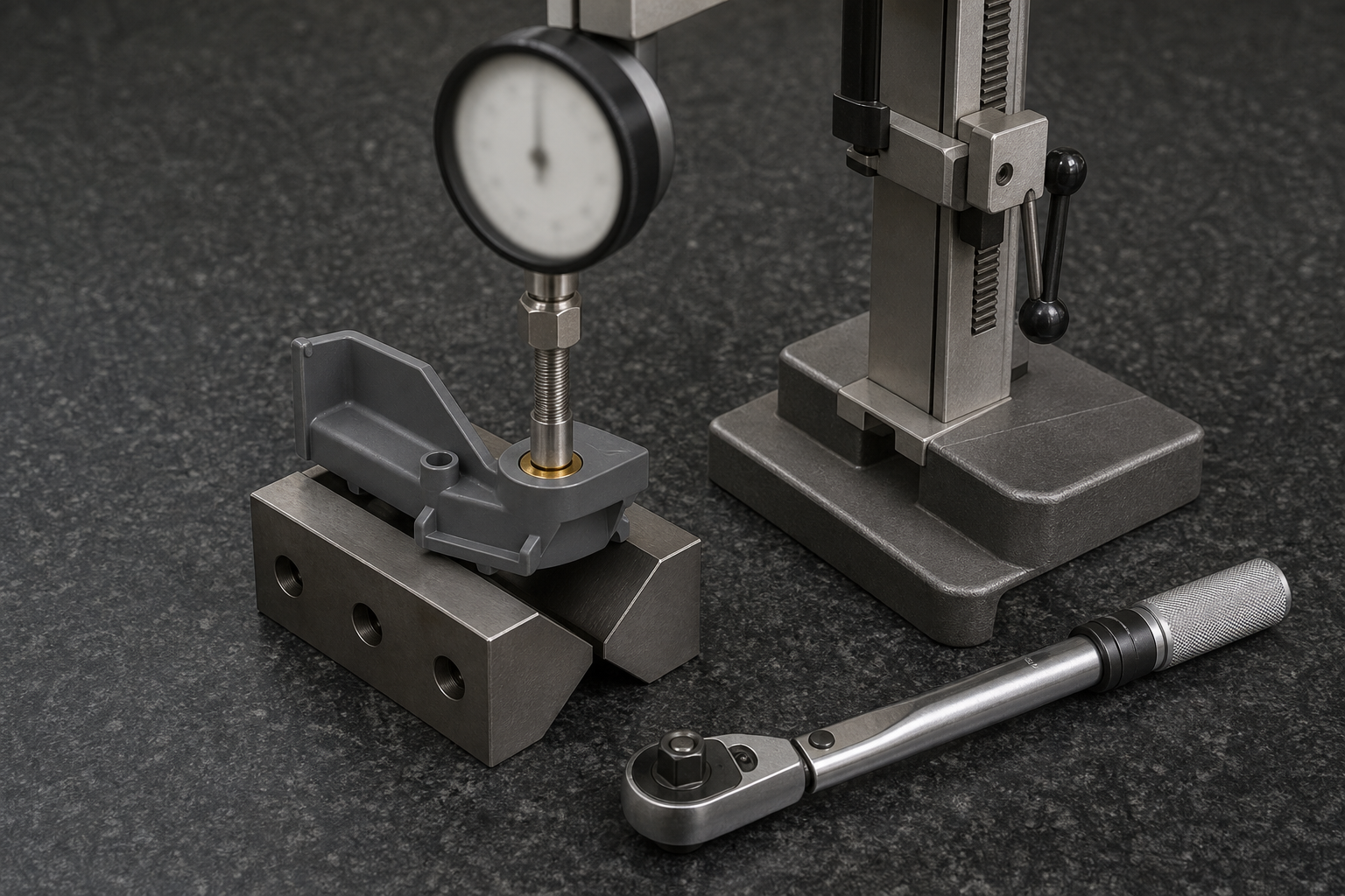
Short answer: the two routes fail in different ways, so they must be validated against different questions. Insert molding fails when the insert moves or the surrounding plastic cracks; overmolding fails at the interface, or at the boundary.
| Validate this | For insert molding | For overmolding |
|---|---|---|
| Position | Insert location in three axes against the drawing, including the effect of injection pressure on a poorly supported insert. | The position of the material boundary, and the thickness of the overmold across the functional area. |
| Load capability | Resistance to being pulled out along the insert axis, and to being turned for a threaded insert. | Bond performance at the interface, including resistance to peeling or delaminating under the load the part will see. |
| Integrity of the surroundings | Whether the polymer around the insert stays sound: no cracking, no sink, no local thinning at the boss. | Whether the substrate deforms or the overmold pulls away at corners, thin sections and the boundary line. |
| Function in service | Whether the assembly still works after the insert has been fastened and unfastened repeatedly, or after the part has seen its service temperature. | Whether a seal still seals, a grip still grips and the elastomer still behaves as intended at the service temperature and chemical exposure. |
| Process stability | Whether inserts are positioned the same at the end of a run as at the beginning, and whether any fixture wear is visible in the samples. | Whether the boundary and the bond are the same at the end of the run as at the beginning, which is where boundary drift usually appears. |
Who sets the acceptance limit. This page does not state pull-out, torque, peel or hardness acceptance values, because they are properties of your part, your insert and your application, not universal numbers. Bring the functional requirement and the service conditions; the test method and limit should be agreed against the drawing and the intended use before the tool is cut, and applied to samples rather than assumed. Where a recognised method is required, it should be named on the drawing or in the purchase specification so that both sides are testing the same thing.
For parts that combine both routes, the validation has to cover the sequence as well: whether the insert survived the overmold shot, whether the second operation moved it, and whether the finished part still meets its dimensional and functional requirements after both steps. This is where a staged route carries more risk than a single-cycle one, and where the extra checks belong.
What to Include in an RFQ
Short answer: the part definition, the materials, the function each material performs, and the volume. Without the interface requirement, a supplier can only quote a tool — not a process.
| Item | Why the supplier needs it |
|---|---|
| 3D CAD and 2D drawing with revision | To assess part structure, insert location, overmold area and the tolerances that matter. |
| Preformed insert drawing, material and any surface treatment | To judge whether the insert suits molding, how it will be located, and what holds it in place. |
| Substrate and overmold material grades | To check compatibility for the exact grades, and to assess temperature and functional requirements. |
| Annual demand, initial order and expected programme life | To compare the routes economically and to size the tool and the automation correctly. |
| Critical functional requirements | To define what has to be validated: insert retention, torque, sealing, grip, wear resistance or another function. |
| Critical dimensions, tolerances and acceptance requirements | To fix the inspection plan and the acceptance criteria before, not after, the first samples. |
| Service environment | To judge temperature, moisture, chemical contact, vibration, cleaning or sterilisation risks that affect both the bond and the elastomer. |
| Target delivery date and planned capacity | To assess the tooling route, the validation schedule and whether the volume can be run at all. |
If you have already been quoted for one route by another supplier, include it. Comparing two routes on the same part is far more informative than comparing one route against nothing — and if the scopes behind them differ, that is exactly what a review should surface. Process depth across all our molding routes is set out on the injection molding services page.
Frequently Asked Questions
When should I use insert molding instead of overmolding?
Use insert molding when a preformed component such as a threaded insert, bushing, pin, terminal or stamping has to be positioned and encapsulated inside the plastic part. Use overmolding when a second material has to add a function to a substrate, such as grip, sealing, cushioning or surface protection. The choice follows the part function, not the process name.
Is insert molding only used for metal inserts?
No. Insert molding is used with metal inserts most often, but the insert can also be a preformed plastic part, a composite, a ceramic or an electrical component such as a terminal or a small board. What defines the process is that a preformed component is loaded into the tool and encapsulated — not the material of that component.
Is overmolding the same as two-shot molding?
Suppliers use the term overmolding in two ways. In the narrow sense it means loading a preformed substrate into a second mold cavity, which is a different route from two-shot molding. In the broad sense it covers any process that applies a second material over a substrate, including two-shot. The question that decides your project is whether both materials are molded in one cycle or in a second operation.
Which process is better for threaded metal inserts?
Insert molding is normally the better fit where a threaded insert has to be positioned and held inside a molded part, because locating the insert in the tool removes a separate assembly step and lets the insert be locked by molded-in features. Post-molding options such as heat-set, ultrasonic or pressed inserts remain competitive at low volume or while the design is still changing.
Which materials can bond during overmolding?
Bonding may come from chemical compatibility between the substrate and the overmold material, from mechanical interlock designed into the geometry, or from both. Compatibility has to be checked for the specific grades you intend to use, not from the family name alone, because grades within the same polymer family can behave differently. Where chemical bonding is uncertain, mechanical interlock is designed in and confirmed on samples.
Does overmolding always require two molds?
No. In the narrow sense overmolding needs a substrate — which can be a bought-in or separately molded part — plus a second mold cavity for the overmold. Where both materials are molded in one cycle in a single tooling system, that is two-shot molding rather than overmolding in the narrow sense, and it uses one machine and one tool.
Which process is more cost-effective for low-volume production?
At low volume or while the design is still moving, neither a complex insert tool nor a two-shot tool is automatically justified. Single-material molding followed by assembly, pressed or heat-set inserts, adhesive or a mechanical joint are often cheaper to start. Compare accumulated cost including tooling, inserts, assembly, inspection and scrap rather than comparing a tooling quotation alone.
What tests should I require for insert-molded or overmolded parts?
For an insert-molded part, the questions are insert position, pull-out resistance and torque resistance for a threaded insert, plus whether the surrounding plastic stays sound. For an overmolded part, the questions are bond performance, delamination and peeling at the interface, the position of the material boundary, and the hardness or function of the overmold. Actual tests and acceptance limits should follow the part function and be agreed before the tool is cut.
Can a part combine insert molding and overmolding?
Yes. A part can carry an encapsulated insert and a second functional material at the same time. This is a sequencing and tooling-architecture question rather than a choice between the two processes: it may be built as two separate operations, or in a more complex multi-material tool, depending on volume, geometry and how much risk the programme can carry.
What alternatives should I consider if material bonding is unreliable?
Where the bond between two materials cannot be made reliable for the intended grades, the options include redesigning the interface to add mechanical interlock, selecting a different combination of grades, separating the functions into two parts joined by a mechanical joint, adhesive or a gasket, or moving to a bonded or fastened assembly. The decision should be made before the tool is cut.
Where Each Subject Lives on This Site
This page covers the choice between the routes. The subjects below are covered in depth elsewhere, and are linked rather than repeated here.
| Subject | Where to read it |
|---|---|
| Overmolding as a process: material pairs, hardness, interface defects, inspection | Overmolding for soft-touch, sealing and functional integration |
| Two-shot and 2K molding: tooling architecture, mold design and economics | Two-shot (2K) injection molding |
| All molding capabilities and tool routes | Injection molding services |
| Mold construction, steel selection and trial stages | Injection mold making in China |
| Cost factors behind a molded part price | Get an injection molding quote |
| Choosing the molding supplier and auditing the process | Choosing a China injection molding supplier |
| Supported resins and material data | Molding materials |
| Certification and quality system status | Quality certifications |
Compare Insert Molding and Overmolding for Your Part
Not sure which process fits your component? Send the part drawing, the material requirements and the expected annual volume. We will review the functional requirements, the material interfaces, the tooling options and the key validation needs before quotation.
What this page does and does not claim
- This page helps you decide which route to evaluate. It does not select a final process for you, and it is not a quotation.
- No pull-out, torque, peel, hardness or cost acceptance value is stated here, because each is a property of your part, your insert and your application. The test method and limit belong on the drawing or in the purchase specification, agreed before the tool is cut.
- The terminology section states that “overmolding” is used in two senses in this industry, and says which sense this page uses. You should confirm which sense your supplier uses, because it changes what is being quoted.
- Boundary conditions such as material compatibility, insert retention and bond performance are confirmed by engineering review and sample testing, not by material names or data sheets.
- Where this page touches a subject our other pages own in depth, it links to them rather than restating them, so that both pages give one answer.