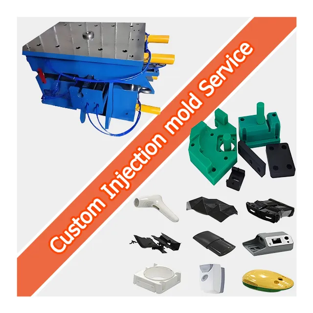
Custom Mold Tooling | Plastic, LSR & Rubber
Place of Origin : Fujian, China
Brand Name : JSD
Model Number : IM-77
Product Material : Steel
Product : plastic mold
Product Name : custom plastic mold
Shaping Mode : Plasitc Injection Mould
Material : Stainless Steel
Color : Customized Colors
Size : Customized Size
Service : OEM ODM Customized
Drawing Format : 2D/(PDF/CAD)3D(IGES/STEP)
Certification : ISO9001
Tolerance : +/-0.005mm
MOQ : 1piece
Description
Custom Injection Mold Tooling · OEM/ODM · Drawing-Based
Custom Injection Mold Tooling for Precision Plastic Parts
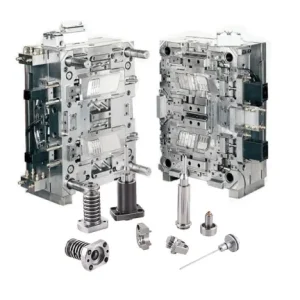
We design and build the steel tool — cavity, core, runners, cooling and ejection — that shapes every part you run. This page covers the mold itself, distinct from recurring injection molding production.
Request a Mold Quote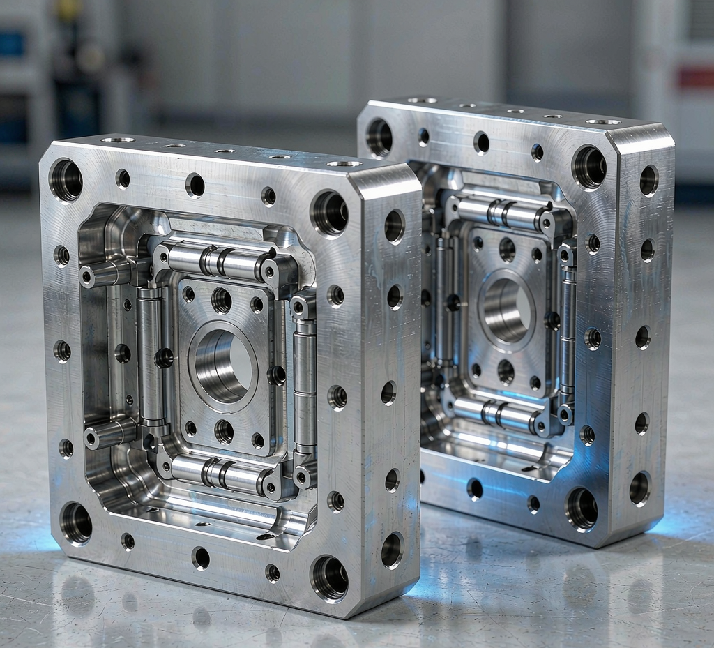
Mold Tooling, Not Just Molding
Buyers often arrive looking for "plastic injection" and mean two different things: a finished part delivered by the thousand, or the tool that makes it. They are different assets with different cost structures, lead times and acceptance criteria. Confusing them leads to quotes that cannot be compared and tools that do not fit the production plan.
Mold manufacturing (this page)
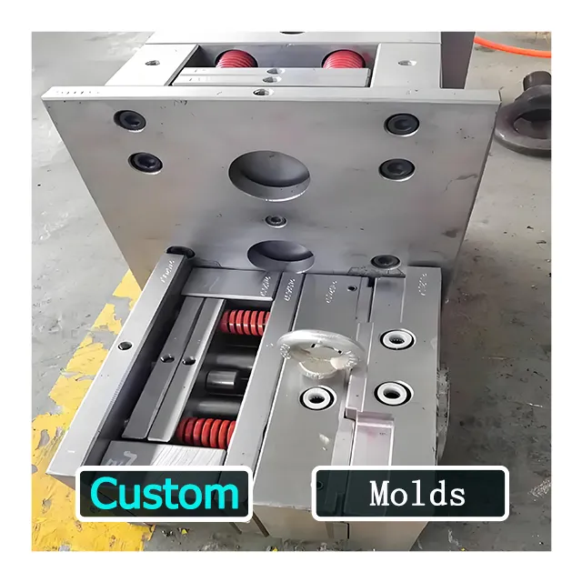
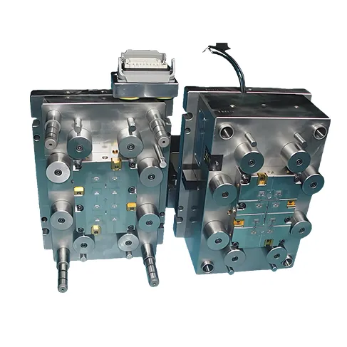
You receive a physical steel tool: machined cavity and core, runner or hot-tip system, cooling circuits, ejection and, where needed, slides, lifters or unscrewing actions. The deliverable is the qualified mold plus first-article samples.
- Deliverable: one owned tool + T1/T2 samples
- Priced on complexity, steel, cavities, finish
- Run by us, by you, or by any molder
Injection molding service
You receive molded parts by the lot. The tool may be one we built, one you already own, or a tool we help you source. The deliverable is a recurring supply of conforming parts.
- Deliverable: parts per order, not the tool
- Priced on resin, cycle, volume, logistics
- Requires a qualified mold to run
If you need both, we scope them as two line items in one project so the tool and the production plan stay aligned. If you only need the tool, the mold leaves our workshop qualified and documented.
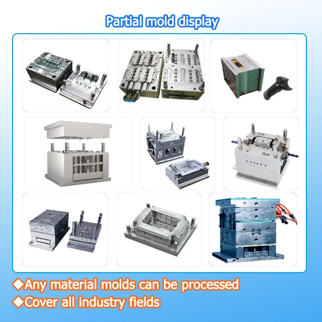
Mold Types We Build
The right mold architecture is decided by volume, part count, resin and the assembly step that follows molding. Below are the tool types we design and machine, with the conditions that favor each.
Prototype & low-volume
Soft or pre-hardened steel, simplified cooling, often single-cavity. Favored when the design is still moving and you need parts to test form, fit and function fast.
Production mold
Hardened steel, full cooling and ejection, built for the planned shot count. Favored when the design is locked and volume justifies a durable tool.
Multi-cavity
Two or more identical cavities in one tool to raise output per cycle. Favored for high-volume, tight-tolerance parts where cavity balance must be controlled.
Family mold
Different part geometries in one tool, molded in a single shot. Favored for kits and assemblies where several components share resin and color.
Insert mold
Metal or pre-molded inserts placed in the cavity before molding. Favored for threaded bushings, electrical contacts and hybrid parts.
LSR & overmold
Liquid silicone rubber molding and two-shot / overmolding of a second material onto a first. Favored for seals, grips and soft-touch interfaces.
Materials: Mold Steel and Molded Resins
Two material decisions sit in every mold project. The first is the steel of the tool; the second is the resin the tool will shape. They are independent and should not be mixed up in a quote.
Mold steel selection
Pre-hardened / economy
P20, 718 and similar for prototype and lower-volume tools where the run does not demand maximum hardness. Faster and lower cost, with good machinability.
Hardened / long-run
H13 (1.2344) and 1.2767 for abrasive resins and high shot counts. Selected when wear resistance drives the total cost of ownership.
Corrosion-resistant
S136 (1.2083) for aggressive or corrosive molding environments and LSR, where the tool must resist staining and pitting.
Mirror / optical
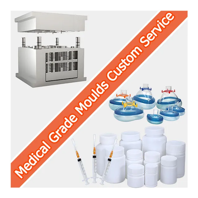
NAK80 and polished S136 for lenses, medical and cosmetic surfaces that require a high-quality molded finish straight from the steel.
Molded material families and their boundaries
The phrase "rubber and silicone" covers material families that are not interchangeable. We tool and process each by its real behavior:
- Thermoplastics (ABS, PC, PC/ABS, PA, POM, PEEK, PP, PBT) — melt, inject, solidify; recyclable through the barrel. The default for most precision parts.
- Liquid silicone rubber (LSR) — a two-part liquid cured in the mold; molded on dedicated LSR equipment with a cold runner. Used for seals, medical and high-temperature parts. This is a distinct tool and process path from thermoplastic injection.
- Thermoplastic elastomers (TPE/TPU) — processed like a thermoplastic but flexible; often overmolded onto a rigid thermoplastic. Not the same as cured rubber.
- Thermoset rubber (FKM, EPDM, NBR, silicone gum) — cross-linked and not re-meltable. Molded on different tooling and cure conditions; we treat it as a specified material path, not a generic "rubber mold."
Tell us the exact resin or elastomer and the grade, and we design the gate, vent, cure and ejection to suit — not a one-size tool claimed to "do rubber, silicone and plastic alike."
Mold Design and DFM
A mold is a system, not a block with a shape machined into it. The design phase decides whether the tool will be cheap to run and easy to maintain, or expensive to fight. Our design work covers:
Part and tool review (DFM)
Draft, wall thickness, undercuts, shutoffs and tolerance callouts are reviewed against molding reality. We flag features that will fight ejection or cause sink and warp before they reach steel.
Mold-flow analysis
Fill, pack, cooling and warp are simulated to place the gate, size runners and confirm the cooling layout, reducing trial-and-error at T1.
Gating and runner
Cold runner, hot tip or valve gate, selected for the resin, cosmetic requirements and scrap target. Gate location is decided with the part function in mind.
Cooling, ejection, actions
Cooling circuits laid for balanced, repeatable cycles; ejection planned for the geometry; slides, lifters and unscrewing actions detailed where the part demands them.
How We Build the Tool
Building a mold is a sequence of controlled steps. Each one is checked before the next begins, so a problem is caught in the step that caused it rather than at final tryout.
- Steel preparation. The block is selected, verified against the certificate and pre-machined to rough stock.
- CNC of cavity and core. The shape is machined to the design, leaving stock for EDM and polish where needed.
- EDM. Fine details, deep pockets and sharp internal corners that cutting tools cannot reach are eroded to form.
- Grinding and fitting. Datums, parting lines and mating surfaces are ground for accuracy and repeatable assembly.
- Polishing and surface. The cavity is polished to the specified finish; texturing or coating is applied where the part calls for it.
- Heat treatment. Hardening and stress relief are applied per the steel plan, then verified.
- Assembly. Cooling, ejection, guide and action components are built into the set and checked for fit and travel.
- Tryout (T1). The mold is mounted and sampled; parts are measured and the tool is adjusted until it conforms.
Tolerances, Scoped Honestly
Tolerance claims are where molding pages most often mislead. A single number quoted across a whole page usually cannot be true for every feature. We scope tolerance by object.
Mold (the tool)
Cavity and core features are machined to tight limits. ±0.005 mm describes qualified features cut under controlled conditions — not a promise applied to every pocket, thread or textured surface. We state which features are held to which limit on the drawing.
Molded part
The part dimension is the cavity dimension plus resin shrink, minus process variation. Final part tolerance depends on material, gate, wall and process window. We confirm achievable part tolerance during engineering review and reference it to ISO 20457 / DIN 16742, not as a blanket figure.
If a page tells you it holds ±0.005 mm on "everything," ask which object the number describes. The honest answer separates the tool from the part, and the part from the feature.
Mold Validation and Verification
Rather than citing customer names or project stories, we describe exactly what we verify on every mold. This is the evidence a procurement or quality team can audit:
Tryout and sampling
T1 parts are produced on the actual tool. We check fill, short shots, flash, warp and cosmetic result, then adjust the tool before committing to volume.
Dimensional verification
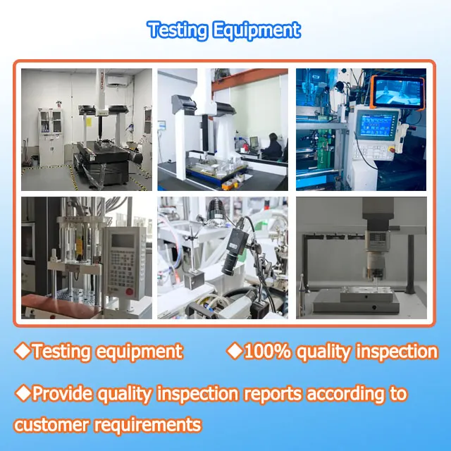
Critical and functional dimensions are checked — by CMM where the feature requires it — and reported against the drawing so conformance is documented.
Tool qualification
Fit of parting line, cooling flow, ejection travel and cycle consistency are confirmed. The mold must run repeatably, not just make one good shot.
Maintenance record
We document a maintenance plan — inspection points, wear items, recommended intervals — so the tool performs consistently across its service life.
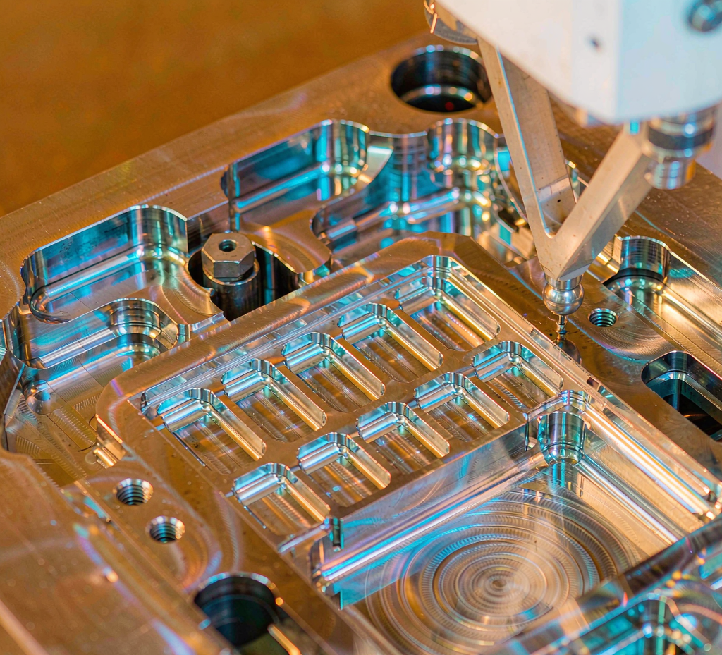
On request we supply the dimensional report, tryout photos and the steel certificate so your incoming inspection has the same evidence we used to release the tool.
Inspection and Quality System
Quality is built into the steps, not bolted on at the end. Controls we apply through the build:
- Incoming verification of mold steel against its certificate
- In-process checks at CNC, EDM, grinding and assembly stages
- Dimensional measurement of sampled parts (CMM where the feature requires it)
- Final tool qualification and sample approval before shipment
- Records retained so a repeat order or a spare component can be matched to the original
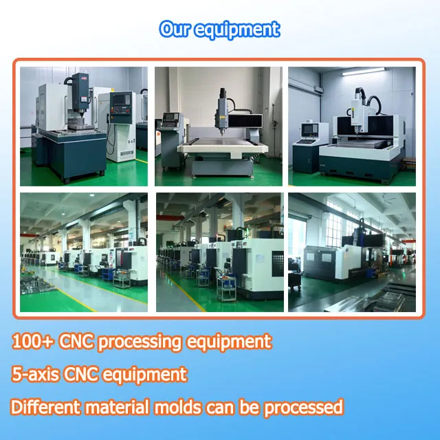
We do not publish a single fixed machine specification; capability is confirmed through engineering review against your part and resin.
Lead Time, MOQ and Starting an RFQ
A mold is a single engineered asset, so the commercial terms are simple: you order one tool, and we plan production parts separately if you want them molded.
MOQ: 1 piece
One custom mold, built to your part. There is no minimum batch of tools; production part quantity is planned per your forecast.
Lead time by plan
Prototype and low-volume tools are faster; hardened production tools with texturing or multi-cavity layouts take longer. We confirm a T1 date in the project plan.
What to send
3D model (STEP/IGES), target resin and grade, annual volume and cavities, critical dimensions with tolerances, and the application environment.
The more precisely you define the part and its function, the more accurate the DFM and the quote. A 2D drawing helps but is not required to begin.
Request a Mold QuoteFrequently Asked Questions
What is the difference between mold manufacturing and injection molding service?
Mold manufacturing is the engineering and machining of the steel tool itself — the cavity, core, runners, cooling and ejection that shape every part. Injection molding service is the recurring production of parts by running that tool on a molding machine. We provide both, but this page covers the tool: you receive a qualified mold, and you can run it at our plant, at your facility, or with another molder.
What tolerance can you hold on the mold and on the molded part?
On the mold, ±0.005 mm applies to qualified cavity and core features machined under controlled conditions — not to every dimension of every part. The molded part tolerance is a process outcome that depends on resin shrink, gate location, process window and part geometry, and is normally referenced to ISO 20457 / DIN 16742. We confirm achievable part tolerance during the engineering review, not as a blanket promise.
Do you make LSR (liquid silicone) and rubber molds? How are they different?
We build molds for thermoplastic injection, for liquid silicone rubber (LSR) two-shot and overmolding, and for thermoplastic elastomers (TPE/TPU). True thermoset rubber (FKM, EPDM, NBR) is molded on different tooling and process conditions; we handle it as a specified material path rather than a generic rubber mold. Tell us the exact elastomer and we will design the tool and process to match.
What mold steel do you use, and how is it selected?
Selection follows the production plan: P20/718 for lower-volume and prototype tools, H13 (1.2344) and 1.2767 for higher wear and longer runs, and corrosion-resistant S136 (1.2083) or mirror-grade NAK80 for optical, medical and LSR applications. We recommend steel based on expected shot count, resin aggressiveness and surface finish, and we supply the steel certificate on request.
What do I need to send for a mold quotation?
Send a 3D model (STEP/IGES), target resin and any specified grade, annual volume and cavity count, critical dimensions with tolerances, and the application environment. A 2D drawing helps but is not required. The more precisely you define the part and its function, the more accurate the DFM and the quote.
What is your typical mold lead time and T1 sample time?
Lead time depends on complexity, steel availability and surface treatment. Prototype and low-volume tools are faster; hardened production tools with texturing or multi-cavity layouts take longer. We quote a committed timeline after DFM and confirm the T1 sample date in the project plan — we do not publish a single fixed number that would not fit every tool.
What is your minimum order quantity for a custom mold?
MOQ is one piece — one custom mold built to your part. Production part quantity is separate and planned per your forecast; the tool itself is a single engineered asset you own.
How do you verify mold quality before shipping?
Every mold goes through T1 tryout, dimensional checking of the sampled parts (CMM where required), verification against the drawing, a mold qualification check (fit, cooling, ejection, cycle), and a sample approval step. We can supply the dimensional report and photos, and we document a maintenance plan so the tool performs consistently over its life.