
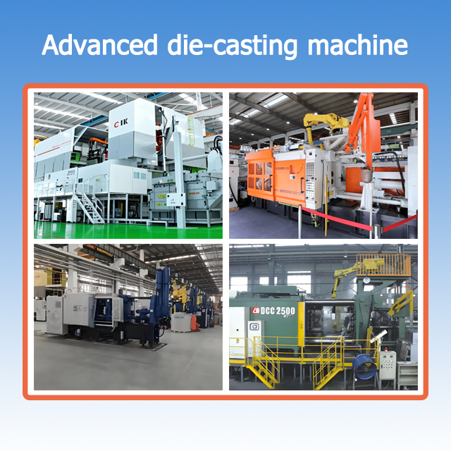
Die-Cast Equipment Bases | Medical & Beauty Trolleys
| Attribute | Details |
|---|---|
| Product Type | Custom Die-Cast Bases & Metal Parts |
| Application | Beauty Trolleys, Medical Trolleys, Portable Trolleys |
| Customization | Available (Size, Shape, Surface Finish) |
Description
Custom Die-Cast Equipment Bases for Medical & Beauty Trolleys
Structural die-cast bases and metal support components built to your drawing for medical equipment trolleys, beauty and aesthetic equipment trolleys, and portable equipment supports. Mounting interfaces, secondary CNC machining, surface finish and inspection are defined with your engineering team before tooling.
What a die-cast equipment base actually does
A mobile equipment base is a structural component, not a trim part. It transfers the weight of the equipment and column into the casters, keeps the assembly stable while it is moved, and provides repeatable locating surfaces for everything bolted to it.
Custom die-cast equipment bases are structural metal components manufactured to support medical, beauty and portable equipment assemblies. Their design typically considers equipment mounting interfaces, structural stiffness, caster attachment, dimensional accuracy and surface finishing requirements. At Goldcattle they are built to the OEM drawing rather than supplied as a fixed catalog item.
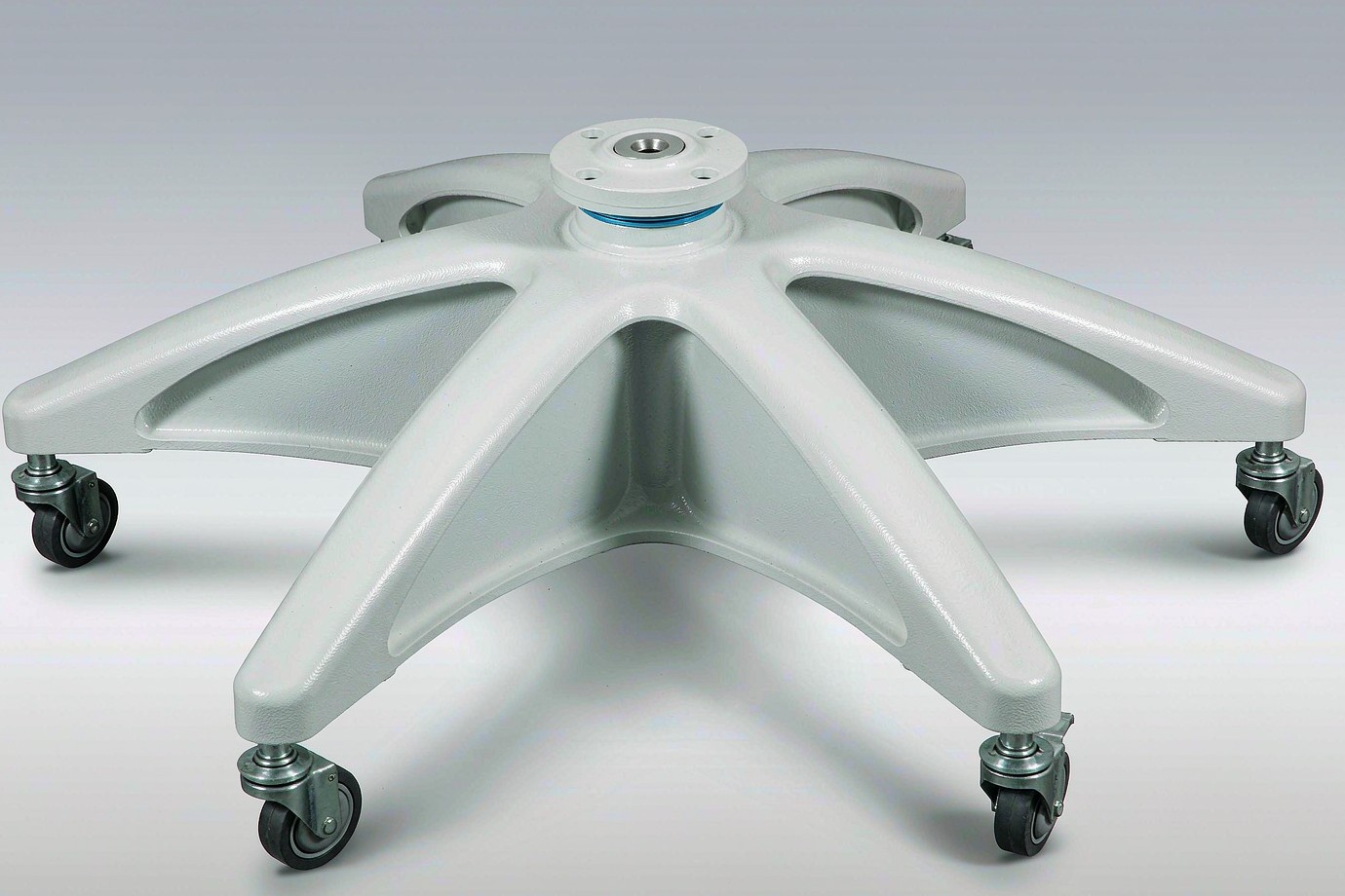
The existing product page identifies this item as Custom Die-Cast Bases & Metal Parts, used on beauty trolleys, medical trolleys and portable trolleys, with size, shape and surface finish open to customization. The published product image shows a five-arm star configuration with caster wheels and a central column interface.
| Function in the assembly | What the drawing has to define |
|---|---|
| Carry the column and equipment | Central bore or flange, bolt circle, locating features, axial load path |
| Transfer load to the casters | Leg count, span, caster pad geometry, hole pattern, thread |
| Resist bending and twist | Rib layout, wall transitions, section changes, fillet radii |
| Locate mating parts | Machined mounting faces, datums, position tolerances |
| Present a clean visible surface | Cosmetic faces, coating area, masking of functional features |
The process chain behind this product is described on our die casting services page. This page starts from the base structure and its interfaces instead of repeating the general process overview.
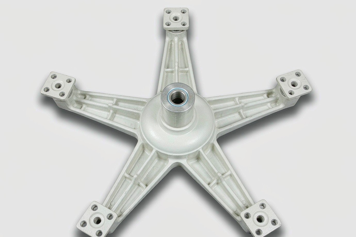
Product fact boundary. The existing product page does not publish an alloy grade, overall dimensions, part weight, load rating, wall thickness, tolerance values, coating specification, inspection reports or product-level certifications. This page therefore explains how each of those inputs is defined, reviewed and verified per project; it does not invent values for them. All product and process imagery on this page is illustrative of the configuration and manufacturing route, and is not a photograph of a specific customer order.
Base forms we can review against your drawing
The five-arm star is the configuration shown on the existing product page. Other structural forms are engineering options to evaluate, not stocked variants.
Distributed caster support
Radiating legs place casters away from the centre to increase the support polygon. Leg count, span and included angles come from your stability and clearance requirements.
Compact, symmetric footprint
A continuous ring or disc can simplify the visible form and the mould parting line, but needs careful rib design to keep stiffness without adding mass.
Ribbed for higher bending loads
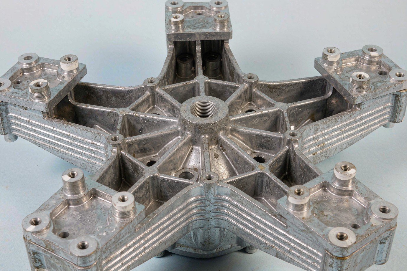
Underside rib networks, locally thickened bosses and smooth section transitions carry the load path from the column to each caster pad.
Defined interface pads
Flat machined pads, counterbores, threaded bosses or insert seats to suit the specified caster fixing and swivel envelope.
Specification basis and mounting interfaces
Because this is a drawing-based component, the specification table states where each value comes from. Nothing below is a published stock dimension or a rated capacity.
| Specification | Basis for this product |
|---|---|
| Product type | Custom die-cast equipment base and metal support components |
| Application | Medical / beauty / portable equipment trolleys |
| Build basis | 2D engineering drawing and/or 3D CAD model supplied by the OEM |
| Casting material | Alloy grade agreed per drawing; the existing page states high-grade metals without naming a grade |
| Casting process | Die casting route selected after drawing and DFM review |
| Overall dimensions | Customized to drawing; no catalog size |
| Structural design | Customer-defined geometry, leg count and rib layout |
| Wall thickness | Set during DFM review against alloy, span and load path |
| Mounting structure | Column, caster and equipment interfaces per drawing |
| Mounting holes | Hole pattern, diameter, counterbore and thread per drawing |
| Critical tolerances | Per drawing and functional interface; no blanket part-wide value |
| Secondary machining | CNC face milling, boring, drilling and tapping as specified |
| Surface finish | Coating or finish agreed per project, with a masking plan |
| Inspection | Dimensional and visual inspection per agreed criteria |
| Production volume | Quoted against tooling approach and annual demand |

Load and stability: what we can and cannot state
Buyers reasonably ask about static load, dynamic load during movement, load distribution between legs, bending resistance, structural rigidity and resistance to tipping. These are properties of the assembled equipment, not of a casting on its own. They depend on total equipment mass, centre of gravity, column height, caster positions and type, accessories, maximum working load and the floor conditions in use.
| Input | Who supplies it | How it is used |
|---|---|---|
| Equipment mass and centre of gravity | Equipment OEM | Defines the load path from column to casters |
| Column height and mounted accessories | Equipment OEM | Defines the overturning moment and tipping review |
| Caster positions, rating and swivel envelope | Equipment OEM | Defines pad geometry, hole pattern and clearance |
| Maximum working load and duty cycle | Equipment OEM | Defines static and dynamic cases for structural review |
| Base geometry, ribs and alloy | Reviewed jointly | Evaluated against the cases above during DFM |
Compliance boundary. For applicable medical electrical equipment, IEC 60601-1 addresses basic safety and essential performance of the complete device, including stability aspects of mobile equipment. Conformity is verified by the equipment manufacturer against its intended use, configuration and risk assessment. A die-cast base is a component and cannot be described as holding a product-level medical electrical equipment certification. We work to the OEM technical file and to our published quality documentation; ISO 9001:2015 is our certified quality system, while AS9100, ISO 13485 and ISO 14001 are described as aligned process controls, not additional certifications.
Choosing a casting alloy for a mobile base
Alloy choice follows the drawing, the load cases and the finish. The grades below are the range listed on our die casting capability material guidance; they are options to evaluate, not a statement about which alloy this particular base is made from.
| Alloy | Characteristic to weigh | Base-selection question |
|---|---|---|
| ADC12 | Fluidity and castability for complex shapes | Does the rib and boss detail need this filling behaviour? |
| A380 | Balance of strength, casting behaviour and cost | Is a general-purpose aluminum alloy sufficient for the load path? |
| A360 | Corrosion and ductility behaviour to evaluate | Does the operating environment justify it? |
| Zamak 3 | Zinc alloy, dimensional stability and surface quality | Is the part small enough for a zinc route to make sense? |
| Zamak 5 | Zinc alloy with a different mechanical profile | Has engineering review confirmed it for this structure? |
| AZ91D | Magnesium alloy with low density | Is weight reduction worth the process and finish constraints? |
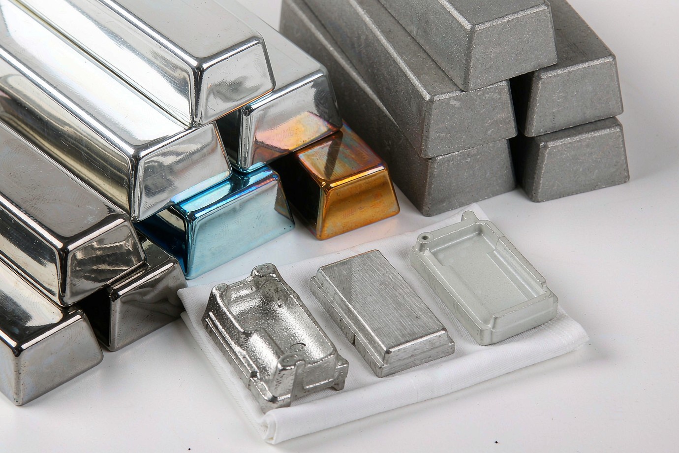
For larger mobile bases, aluminum alloys are often the first route to evaluate, but the decision also depends on stiffness, section thickness, caster loads, finish and total part weight. We do not state that one alloy is universally better than another. The wider reference is on our materials hub. Material grade, temper and mill documentation are confirmed before quotation and checked on arrival.
DFM decisions that determine whether a base casts well
Most cost and quality problems on a base are decided before the tool is cut. The items below are initial engineering references, confirmed per project; they are not fixed values or universal rules.
| Design item | What the review looks for | Why it matters on a base |
|---|---|---|
| Wall thickness and transitions | Uniform sections, gradual changes, no isolated heavy masses | Reduces sink, porosity and distortion on long radiating legs |
| Reinforcement ribs | Rib direction follows the load path, with sensible rib-to-wall ratio | Carries bending load without adding unnecessary weight |
| Mounting bosses | Boss placement, cored holes, local feed and machining allowance | Keeps caster and column interfaces sound and machinable |
| Fillets and radii | Generous internal radii, no sharp re-entrant corners | Improves metal flow, reduces stress concentration and tool wear |
| Draft angles | Draft consistent with the parting direction on legs, ribs and bosses | Allows ejection without dragging or scoring cosmetic faces |
| Parting line and slides | Parting line placed away from visible and functional faces where possible | Limits flash trim work and protects appearance and flatness |
| Machining allowance | Defined stock on faces, bores and hole patterns that are finished later | Keeps the datum scheme stable between casting and CNC |
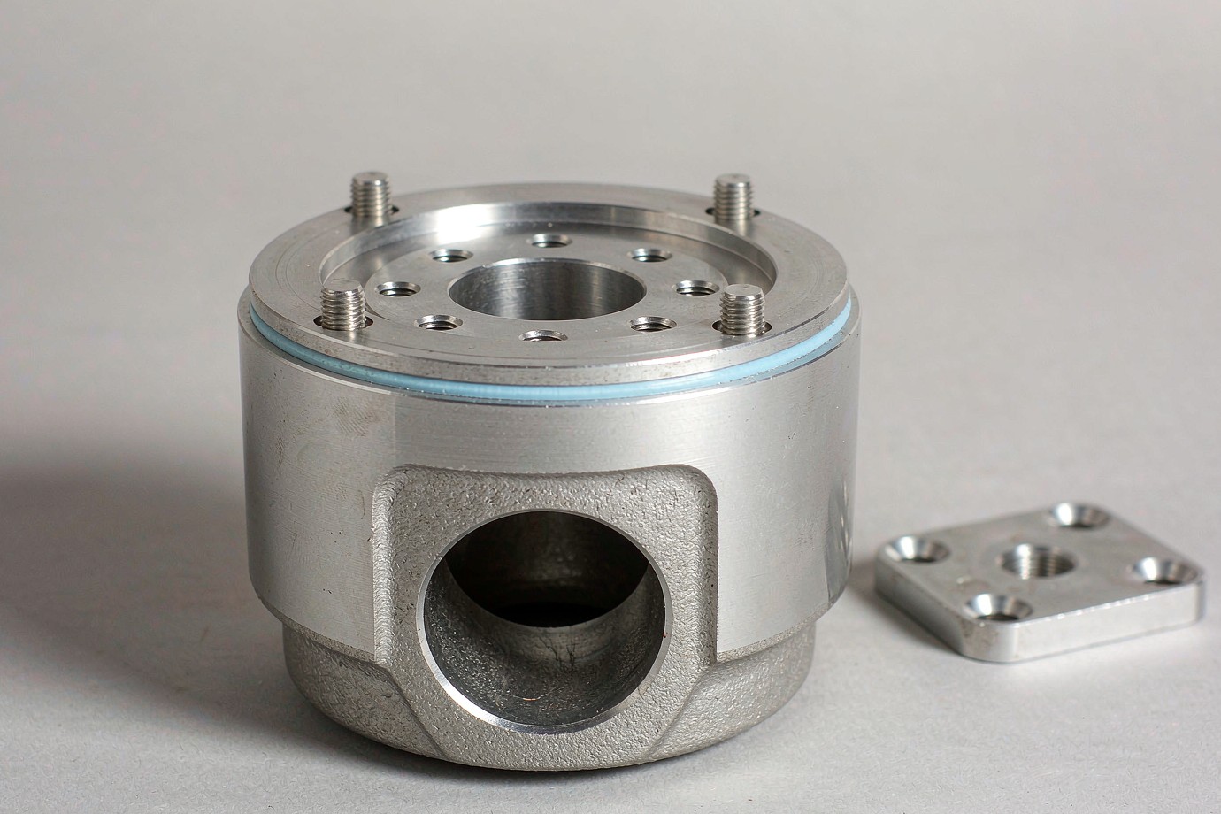
Interfaces first, geometry second
We read the drawing from the assembly outward: which face locates the column, which pads carry the casters, which holes must be positioned to a datum, and which surfaces must stay free of coating. The casting is then designed to deliver sound material at those points.
- Central mounting bore — diameter, depth, flange flatness and bolt circle.
- Caster pads — pitch, thread, counterbore and swivel clearance.
- Threaded bosses — core size, engagement length and machining access.
- Locating features — dowel holes, steps or flats to a stated datum.
- Assembly clearance — space for fasteners, brake levers and cable routing.
Any dimensional reference values discussed during review are initial engineering references, confirmed per project, and are not fixed values that apply to every base.
From casting to a machined, finished base
The casting provides the shape; secondary operations create the interfaces. Keeping both under one quality system is what holds hole position and mounting-face flatness across repeat orders.
Drawing & DFM
Geometry, alloy, interfaces and CTQ features reviewed.
Tooling
Mould design, parting line, slides and sample plan.
Casting & trim
Die casting, gate removal, flash trim and deburr.
CNC machining
Face milling, boring, drilling and tapping.
Finishing
Coating or agreed finish, with functional masking.
Inspection
Dimensional, cosmetic and final checks, then packing.
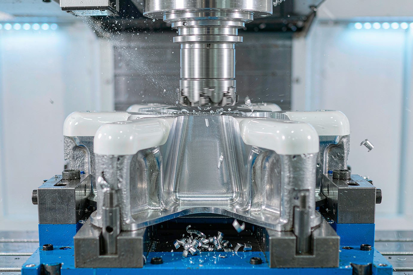
| Post-casting operation | What it controls on a base |
|---|---|
| Face milling | Flatness of the column and caster mounting faces against the stated datum |
| Boring | Central column bore size and its relationship to the locating feature |
| Drilling | Caster hole pattern position, diameter and depth |
| Tapping | Thread class and effective engagement length for caster and column fixings |
| Counterboring | Fastener head seating, recess depth and assembly clearance |
| Deburring | Edge break at hole mouths, ribs, pads and the trimmed parting line |
All six core processes — CNC machining, injection molding, mold making, 3D printing, die casting and sheet metal fabrication — are performed in-house under one ISO 9001:2015 quality system. For the machining scope see CNC machining services; for the wider custom casting route see custom die casting parts services.
Cosmetic quality and functional masking
On trolley bases the visible face is part of the product appearance, while the mounting faces are functional. Both need to be specified separately so the coating does not change a fit.
| Aspect | What to state on the drawing or specification |
|---|---|
| Cosmetic faces | Which surfaces are visible in the assembled equipment, and the accepted appearance criteria |
| Colour and texture | Colour reference, gloss level and texture expectation agreed per project |
| Masked features | Threads, bores, locating faces and earthing points that must stay uncoated |
| Coating thickness | Reviewed together with threaded and mating dimensions before approval |
| Cleaning and corrosion | Cleaning agents, disinfectants and environment the equipment will actually see |
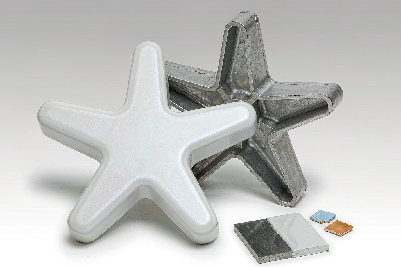
Availability is project-specific. The existing product page lists surface finish as customizable but does not name a process. Powder coating, wet painting, anodizing for suitable aluminum alloys and as-cast or blasted appearances are options to discuss; only treatments confirmed as available for the specific project are quoted. We do not publish a coating durability figure, a corrosion-test result or a colour claim on this page. Cleaning and corrosion behaviour is evaluated against the environment stated by the OEM.
Dimensional inspection and verification
A base fails quietly when a caster hole pattern or mounting face is slightly off: the trolley still assembles, but it wobbles or will not sit level. Inspection scope is therefore agreed before tooling, not after the first batch.
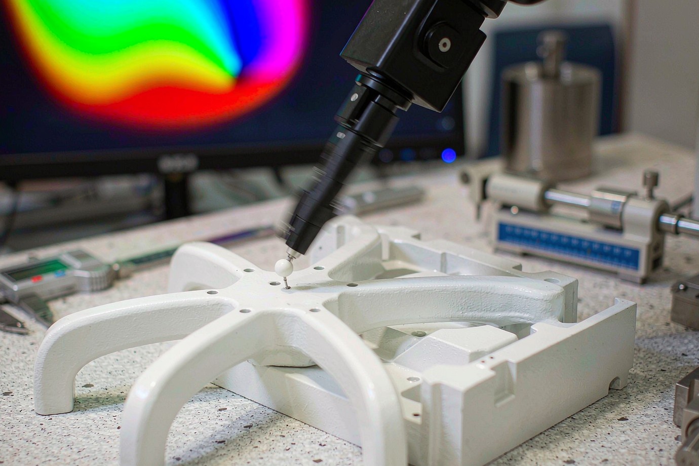
What gets checked
| Quality check | Inspection focus |
|---|---|
| Incoming material | Alloy grade and material documentation |
| First article | Drawing dimensions and critical features |
| Mounting holes | Diameter, position, counterbore and thread |
| Mounting face | Flatness against the stated datum |
| Geometric | Relevant perpendicularity and parallelism |
| Cosmetic | Surface defects, flash and coating appearance |
| Final | Critical drawing requirements and batch records |
Documentation scope. Reports, first-article inspection per AS9102, material certificates and sampling plans are available on request and scoped to the order. This page intentionally does not display sample inspection reports, process-capability indices, scrap or yield figures, load-test certificates or customer case data, because no verified source documents for this specific product were published. Where structural verification is required, we agree whether it is performed by us or by the equipment OEM as part of whole-device validation. Tolerance and datums follow ASME Y14.5-2018 (R2024) or ISO GPS / ISO 22081:2021 as stated on the drawing; the two systems are not interchangeable.
Three procurement contexts, one component family
These markets share a base architecture but do not share the same evaluation criteria. The notes below describe what each buyer typically asks us to define first.
Stability and repeatability
Mobile diagnostic and instrument carts, monitor stands and treatment trolleys. First questions: caster interface, column mounting, load cases specified by the OEM, cleaning environment and dimensional consistency across repeat orders.
Appearance plus structure
Beauty machine trolleys and skin-care equipment stands. First questions: visible-face finish, colour consistency, lightweight feel, ease of cleaning and the balance between cosmetic form and structural rigidity.
Weight and transport
Portable instrument stands and compact mobile frames. First questions: part weight, envelope, transport stability, mounting compatibility and durability of the finish in transit.
Related die-cast components and the product family are listed in the die casting product category. This page stays focused on the base structure and its interfaces rather than repeating those listings.
From drawing to repeat orders
Three common entry points: a new base for a new device, a replacement or redesign of an existing base, and a drawing-based cost review before committing to a production tool.
| Stage | What happens | What you receive |
|---|---|---|
| 1. Technical review | Drawing, CAD, interfaces, alloy, finish, quantity and CTQ features reviewed | Scope confirmation and open questions before quotation |
| 2. DFM and tooling proposal | Parting line, ribs, draft, machining allowance and tool concept evaluated | DFM feedback and a tooling approach agreed per project |
| 3. Sample | Tooling, sample casting, secondary machining and finishing | Sample parts for fit and appearance evaluation |
| 4. Approval and production | Drawing revision, inspection criteria and finish reference frozen | Batch production to the agreed baseline |
| 5. Repeat orders | Same revision, same inspection criteria, same finish reference | Consistent parts with controlled change management |
Prototypes are typically 3-7 working days, low-volume 7-20 working days and production 15-25 working days after file and quote confirmation; dates are confirmed per order. MOQ is 1 piece. We do not promise a specific price or delivery date before engineering review, and shipping terms are confirmed per order rather than published as a general condition of sale.
What to send for a base quotation
The list below is the information that lets us quote the casting, tooling, machining and inspection accurately. There is no input form on this page — use the button to open our secure quote window.
Information checklist
Send your 2D drawing and 3D CAD model with as many of the following as are already defined. Missing items become review questions rather than assumptions.
Note: this page intentionally carries no input form. Click Send Your Base Drawing for Review to open our secure quote window and attach your files with the details above.
We review the casting route, interfaces and inspection scope before returning a quotation.
Frequently asked questions
Can you manufacture custom die-cast equipment bases from engineering drawings?
Which materials are suitable for medical or beauty equipment bases?
Can die-cast equipment bases include caster mounting holes?
Can you machine the mounting faces after casting?
What dimensional tolerances can be achieved on a die-cast base?
What surface finishes are available for equipment bases?
Do you provide load ratings or stability certification for the base?
How is tooling cost handled for low-volume projects?
Can you support prototypes, low-volume and repeat production orders?
What information is required for a die-cast equipment base quotation?
Have a base drawing to review?
Send the drawing and we will review the casting route, caster and column interfaces, machining scope, finish and inspection plan before quoting — from one sample to repeat production.
Xiamen Goldcattle Plastic & Metal Products Co., Ltd. — Founded in 1998 · Customers in 100+ countries · ISO 9001:2015 certified.