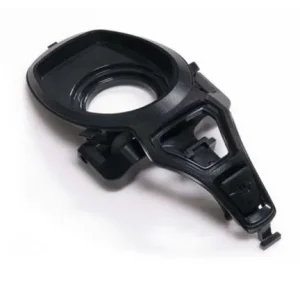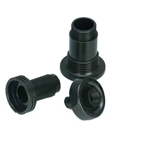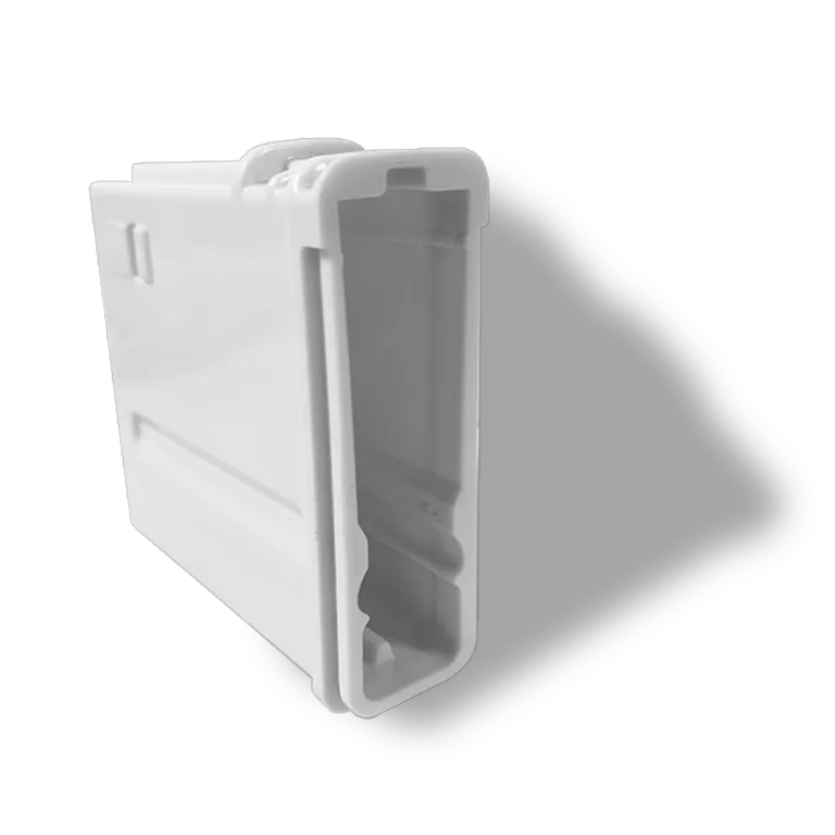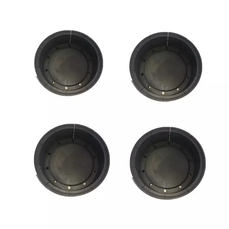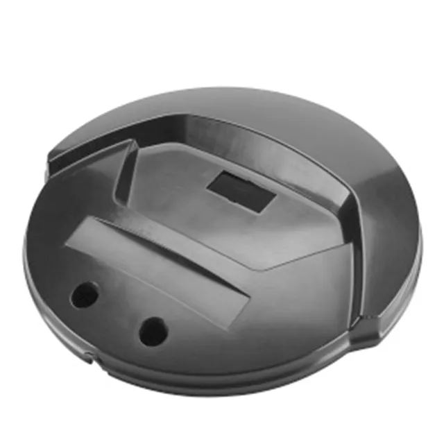


Precision PC Injection Molding | Electronic Parts
Brief specification of custom injection molded parts
Place of Origin : XiaMen, China
Brand Name : JSD
Model Number : Custom
Product Material : Plastic
Product : Plastic Parts
MOQ : 1Piece
Lead time : Sample: 7day; Production: 10-20 days.
Trade Terms : EXW / FOB / CIF
Drawing format : .pdf / .dwg / .igs / .stp / x_t.
Tolerance : +/-0.005mm
Payment Terms : 50% desposite, 50% before shipping
Quality Control : 100% inspection before shipping
Packing : Custom
Shipment Terms : Express /Air freight /Sea freight
Description
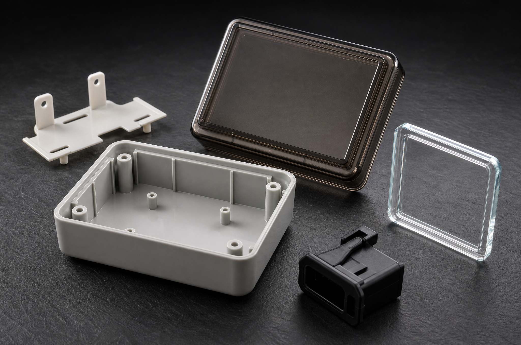
Injection Moulding · Polycarbonate (PC)
Custom Polycarbonate (PC) Injection-Molded Parts for Electronic Products
Enclosures, covers, bezels, windows, internal frames and connector bodies, moulded to your drawing in PC, glass-filled PC or PC/ABS.
- Polycarbonate (PC)
- ±0.05 mm general
- Clear, tinted or opaque
- Tooling 3–6 weeks
- Written for electronic-product parts — not a general injection-moulding page.
- Grade, wall, gate and appearance are reviewed together, because a clear part and an opaque part are different projects.
- No tolerance, rating or lead time is quoted here without the part it applies to.
What this part is, and what the page is for
This is a build-to-drawing part, not a catalogue item. The material is polycarbonate, the geometry is yours, and the three things that decide whether it works — grade, wall and appearance — are settled before a tool is cut.
What we mould
Enclosure halves and covers, face bezels, transparent and tinted windows, light-pipe covers, internal mounting frames and brackets, connector bodies, battery compartment parts and button caps — the structural and cosmetic plastics inside an electronic product rather than its electronics.
Parts are quoted from a STEP model plus a dimensioned drawing. Where the drawing has no cosmetic class, no critical-dimension list and no grade, the DFM review says so before tooling rather than after T1.
What this page is not
It is not a general moulding capability page, and it does not re-explain clamping force, tool steel or the moulding workflow. Those sit on the injection moulding services page, together with the published process envelope this page quotes.
It is also not a materials catalogue. PC is one resin family with several quite different grades, and the differences that matter to an electronic product are the ones on this page.
Specification
Ten parameters are fixed for this part family and eight are set by your drawing. Keeping the two apart is what stops a quotation being built on an assumption.
- Product
- Custom PC injection-moulded parts for electronic products Fixed
- Process
- Thermoplastic injection moulding, single-shot; insert and two-shot where the project needs them Fixed
- Base material
- Polycarbonate (PC) Fixed
- General tolerance
- ±0.05 mm on general dimensions; ±0.02 mm on precision features, confirmed per feature Fixed
- Wall thickness envelope
- 0.4–4.0 mm process range; the nominal wall for a given part follows the grade and the flow length Fixed
- Clamp range
- 50–650 T, selected by projected area and cavity count Fixed
- Drawing formats
- STEP, IGES, STL, DWG, DXF, PDF. The dimensioned 2D drawing is the controlling document Fixed
- Quality system
- ISO 9001 Fixed
- Trade terms
- EXW, FOB, CIF Fixed
- Payment terms
- 50% deposit, 50% before shipment Fixed
- PC grade and supplier
- Grade designation, supplier and data sheet — generic "PC" is not a specification Drawing
- Critical dimensions
- Which features are toleranced, at what value, measured from which datum Drawing
- Optical requirement
- Transparent, translucent or opaque; colour and tint; permitted haze level for a window Drawing
- Flame retardancy
- Rating and the wall thickness it was tested at, where FR is required Drawing
- Surface and texture
- SPI polish grade or VDI texture, and which faces are cosmetic, functional or hidden Drawing
- Tooling route and cavity count
- Rapid or production tooling; cavities sized to the annual volume Drawing
- Assembly features
- Snap fits, screw bosses, heat-stake posts, insert positions and their tolerances Drawing
- Inspection and documents
- Which characteristics are measured, by what method, at what rate, and which reports ship with the order Drawing
Polycarbonate materials and grade selection
Polycarbonate is chosen for three properties: impact strength, heat resistance and dimensional stability. Which grade delivers them depends on the part, and every grade that improves one of the three takes something back somewhere else.
| Grade family | What it buys | What it gives up |
|---|---|---|
| General-purpose PC | High impact, heat resistance, low and predictable shrinkage, good dimensional stability | Notch sensitivity; limited resistance to alkalis and many solvents; must be dried before processing |
| Optical / transparent PC | Clarity for windows, light covers and display bezels; can be tinted or smoked | Every flow mark, weld line and gate blush is visible; needs a polished cavity and a hot mould, and the cosmetic yield is lower |
| Flame-retardant PC | A UL 94 rating at a defined thickness, for parts inside equipment that must meet a flammability requirement | Impact and flow typically drop, the part is usually opaque, and the additive package is a separate compliance conversation |
| PC/ABS blend | Better flow than PC, easier moulding, improved resistance to some chemicals, lower cost per part | Lower heat resistance and lower impact than PC; not transparent; not a drop-in for a PC specification |
| Glass-filled PC | Higher stiffness and lower thermal expansion, for frames and structural brackets | Anisotropic shrinkage that complicates flatness; matte fibre-revealing surface; reduced impact; faster tool wear |
| UV-stabilised PC | Colour and impact retention on parts that see daylight | Higher material cost, and it delays rather than prevents yellowing; a hard-coated or film surface may still be needed |
The chemical limit that catches electronics projects
Polycarbonate is attacked by alkalis, ammonia and amines, and it stress-cracks under load when it meets many solvents, adhesives and cleaning agents. The failure rarely appears during moulding. It appears weeks later as a network of fine cracks around a boss or along a snap-fit, and the moulding process is then blamed for something an assembly chemical caused.
For that reason the review asks what the part will meet after it leaves the tool: the cleaner used on the line, the adhesive or gasket that touches it, the conformal coating, the solvent in the label, the hand cream on the operator. Where any of those is incompatible, the answer is usually a PC/ABS blend, a different adhesive, or a protective geometry that keeps the stress below the cracking threshold — and it is far cheaper to decide that before the tool exists.
Why polycarbonate behaves differently from ABS or PP
Six characteristics separate a PC project from the same part in a commodity resin. Each one moves a decision that would otherwise be routine.
1. High melt viscosity
PC resists flow more than ABS or PP, so filling the same wall needs more pressure and a hotter melt. That pushes the tool towards generous gates, hot runners and stiffer plates, and it makes a thin wall with a long flow the first thing to check rather than the last.
2. Moisture sensitivity
The resin must be dried and kept dry through the hopper. A wet shot looks acceptable on an opaque part and is visibly streaked on a clear one — which is why the same drying rule matters far more on a window than on a bracket.
3. Notch sensitivity
A sharp internal corner, a deep gate mark or a gouge from an ejector pin is a crack starter in PC. Radii at rib bases, boss roots and snap-fit hinges are not cosmetic; they are what keeps the part from failing in a drop test.
4. Frozen-in stress
Fast filling and uneven cooling leave stress in the part. On an opaque part it shows as warpage; on a clear part it shows as birefringence and, later, as crazing. A stress-relief anneal can be specified where the application justifies it, and it is a process step, not a material property.
5. Visible flow history
On a transparent part, the gate area, the weld line and the last point to fill are all readable. There is no hiding them with texture. Gate position, gate size, melt temperature and cavity polish are the four levers, and all four are fixed before the first shot.
6. Shrinkage is low, not zero
PC shrinks less than a semi-crystalline resin, which is why it holds dimensions well — but it still shrinks, and differently along and across the flow. A tool cut to nominal will not produce a nominal part, and the difference is what the tolerance conversation is actually about.
Design for manufacturability: what the review checks
The DFM review is not a courtesy. On an electronic part it is where the assembly tolerances, the cosmetic faces and the tooling cost are decided, and every item below is cheaper to change on a screen than in steel.
| Feature | What the review checks | Why it matters here |
|---|---|---|
| Wall and ribs | Nominal wall against flow length; rib thickness as a fraction of the wall; transitions stepped rather than abrupt | A sink on the outside face of an enclosure is a cosmetic reject; a rib that is too thick also warps the face it was meant to stiffen |
| Screw bosses | Boss wall thickness, root radius, depth, and whether the boss can be cored or gusseted | Bosses are the thickest section on most enclosures, so they sink, crack at the root, or distort the mating face |
| Snap fits | Cantilever length to thickness, allowable deflection strain for PC, and where the beam root sits | PC tolerates more deflection than a brittle resin but less than a soft one; a beam designed for ABS will either not latch or break |
| Draft | Taper on every vertical face, increased where texture is specified | Textured PC releases harder than polished PC, and a dragged wall shows as a scuff on a visible side |
| Undercuts | Whether the feature can be formed by a lifter, a slide or a bump-off, and what that does to tool cost | Internal clips and connector latches are usually undercuts; the choice between a slide and a bump-off is a cost decision |
| Gate position | Distance from the cosmetic face, vestige location, and whether a hot tip can be used | On a clear part the gate is visible; on an opaque one the vestige can still interfere with a mating surface or a label |
| Parting line | Whether the line falls on a hidden edge, and how it aligns with the texture direction | Two halves that part on a visible face show a line no polishing removes, and the customer sees it before the moulder does |
| Tolerance stack | Which dimensions drive assembly — boss pitch, snap engagement, window aperture, connector position | Moulded tolerances have to be allocated across the stack; asking every feature to hold the same band raises cost without improving fit |
Appearance control: surfaces, transparency and colour
An appearance specification is a document, not an adjective. "Good finish" cannot be inspected, and it is the single most common reason a sample is rejected after the tool has been built.
| Class | Where it applies | What is normally accepted |
|---|---|---|
| A — cosmetic | Faces visible on the assembled product: front cover, bezel, top surface | No visible flow marks, no gate blush, no ejector witness, no scuff. Weld lines only where a drawing shows them |
| B — functional | Mating faces, seal lands, sliding surfaces, label areas | Flow marks permitted; gate vestige flush and within a stated height; flatness and texture governed by function, not gloss |
| C — hidden | Internal surfaces, ribs, bosses, areas inside the closed product | Short-shot-free, structurally sound, no flash that interferes with assembly. Cosmetic defects accepted |
Marking the drawing with A, B and C does two things at once. It tells the toolmaker where to polish and where not to spend time, and it gives the inspector a rule that does not depend on opinion. A part with one A face and the rest C is a much cheaper part than the same geometry with every face called cosmetic, and the difference is decided before the steel is cut.
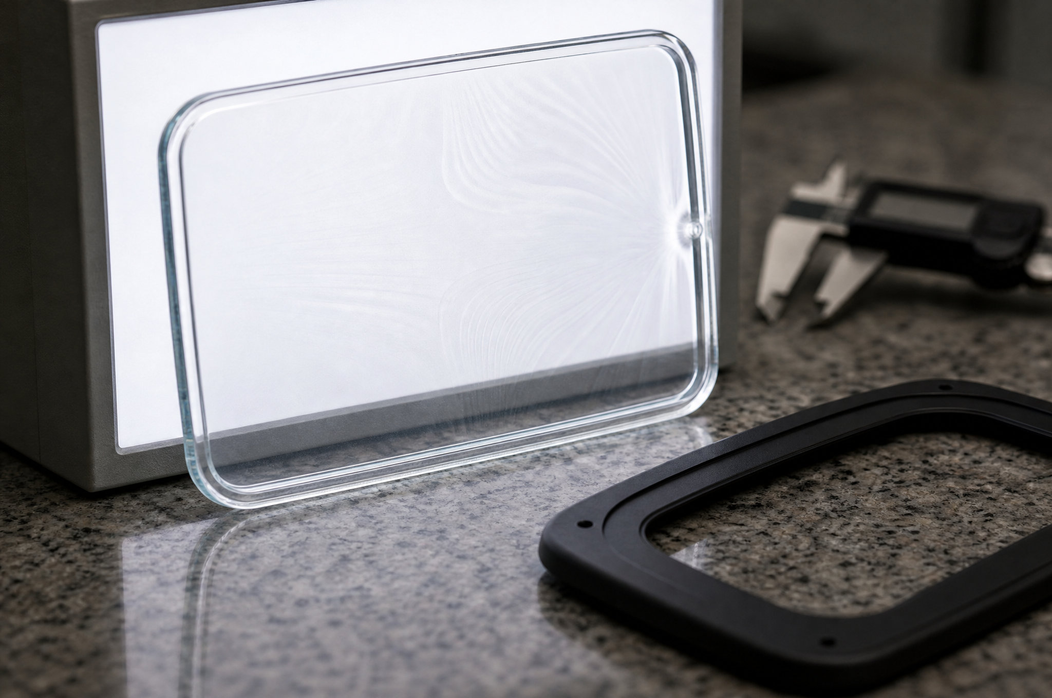
Transparent PC is an appearance specification
For a window or a light cover, the requirement is not "clear" but a combination of light transmission, haze, tint and permitted defects inside a defined aperture. Four things decide whether you get it: the grade, the cavity polish, the gate position and the melt temperature. A polished cavity on a cold mould still produces a hazy part; a hot mould with a small gate produces a halo at the gate.
Weld lines are the usual argument. A clear part with a single gate has one flow front and no weld line; a part with a hole in the middle splits the front and has one, in a place the geometry chose. If the drawing has a window in the centre, that weld line is a design consequence, so decide early whether it is acceptable, whether it can be hidden behind a bezel, or whether the aperture has to move.
Tooling routes, cavity count and mould ownership
The mould is the largest single cost in the project and the one variable that changes the unit price most. Which route is right depends on what the tool has to prove, not on what it costs.
| Rapid / bridge tooling | Production tooling | |
|---|---|---|
| Mould construction | Aluminium or P20, single or low cavity count | Hardened steel, multi-cavity, hot runner where the volume justifies it |
| Purpose | Prove form, fit and function, or bridge to launch | Run the programme at volume with stable yield |
| Published life | Short-run, suited to validation quantities | 100k to 1,000k+ shots depending on steel |
| Economical from | Roughly 1,000 parts | Roughly 5,000 to 10,000 parts upward |
| Best used when | The design is not frozen, or the market has not been tested | The design is approved and the annual volume is known |
Cavity count is a volume decision with a technical floor. One or two cavities keep the tool cheap and the validation simple, which suits a low volume or a large part. Four to eight cavities are the common production answer for a hand-held enclosure. Beyond that the tool needs a balanced hot runner, a stricter cooling design and a part-weight check across every cavity, because an unbalanced multi-cavity tool produces parts that are dimensionally identical and functionally different.
The mould is the customer's asset. It is stored and maintained here, and can be shipped on request. That matters for an electronic product because a programme usually outlives its first tool: the enclosure is revised, the connector changes, the product moves to a second generation. A tool that cannot be transferred is a tool that cannot support that.
Inspection: what is measured, how, and how often
"100% inspection before shipping" names a rate without naming a characteristic. An inspection plan names the characteristic, the method, the record and the rate — and those four are what a supplier quality engineer will ask for.
| Characteristic | Method | Rate |
|---|---|---|
| Critical dimensions | CMM or dedicated gauge, measured from the stated datum | Full first article at T1; sampling in production, expanded where capability is thin |
| General dimensions | Calipers and gauges | Sampling per lot |
| Assembly features | Check with the mating part or a gauge modelled on it | At T1, and at each production start |
| Cosmetic surfaces | Visual against the approved sample, under defined lighting, at a stated distance | 100% on Class A faces where the order specifies it |
| Colour | Against an approved chip under a stated light source | At start-up and on colour change |
| Material identity | Grade and lot recorded against the order; declaration on file | Every lot |
| Part weight | Per cavity, recorded during sampling | At T1, and on request in production |
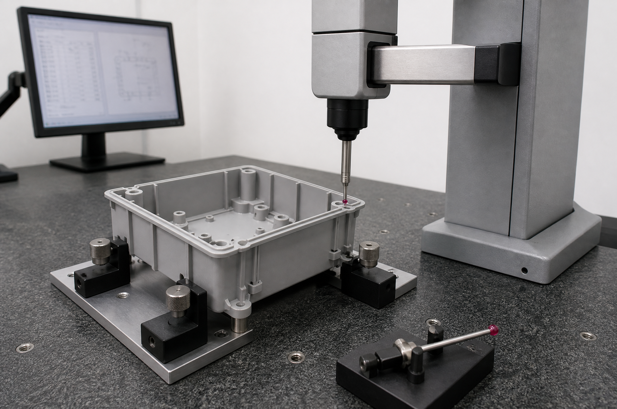
The documents that normally ship are a first-article report, a dimensional report, an inspection record and the material declaration for the grade used. If your quality function needs a different format or an additional record, it has to be named on the enquiry, because it changes what is arranged during production rather than after it.
Material compliance, and where our statement stops
Compliance attaches to the finished electrical equipment, not to a bag of moulded parts. What we can supply are the material declarations that feed your file, plus a statement about the parts we made.
| Requirement | What it covers | What we can provide |
|---|---|---|
| RoHS | Restricted substances in electrical and electronic equipment under Directive 2011/65/EU as amended, assessed at homogeneous-material level | The material declaration for the specified grade, and a statement for the parts we mould. Conformity of the finished device remains the equipment producer's |
| REACH | Substances of very high concern in articles above 0.1% by weight, with an information duty to the recipient | Supplier declarations for the resin, colourant and any additive package, so the substance position can be assembled |
| UL 94 | Flammability of a plastic specimen at a defined thickness, recorded on the material's yellow card | The grade's rating and the thickness it applies to. A rating does not transfer to a wall thinner than the one tested |
Two boundaries are worth stating plainly. First, a flame-retardant grade is not a flame-retardant part: the rating belongs to a specific grade at a specific thickness, and a 1.5 mm wall in a grade rated at 3.0 mm is not rated at all. Second, a declaration of material composition is not a conformity assessment of the product. We are not the equipment manufacturer, we do not place the product on the market, and we cannot sign the declaration of conformity that goes with it.
From drawing to production
Six stages, each with a decision that has to close before the next one starts. The dates that matter are the gate dates, not the total.
RFQ
Model, drawing, grade, volume. The reply states what is missing before it states a price.
DFM review
Wall, bosses, snap fits, draft, undercut, gate and parting line, each flagged with the reason.
Mould design
Cavity layout, runner, cooling, ejection and the cosmetic faces the tool must protect.
Tooling
Typically three to six weeks for a standard tool, longer for multi-cavity or complex action.
T1 and approval
First shots measured against the drawing, corrected, then sampled against the agreed cosmetic standard.
Production
Validated tooling, in-process checks, final inspection and the documents named on the order.
Two timing questions are worth asking at quotation rather than at shipment. What does the sample date count from — mould completion, T1, or sample approval? And how many modification rounds are included before the schedule is re-planned? A supplier who answers both has thought about the project; one who quotes a single number has not.
Typical PC parts in an electronic product
Suitability for a specific product, environment or standard is confirmed per project. The list shows the part types the process suits, not a stock range.
- Enclosure halves
- Front bezels
- Display windows
- Smoked covers
- Light covers
- Internal frames
- Mounting brackets
- Connector bodies
- Button caps
- Battery covers
- Terminal blocks
- Sensor housings
Polycarbonate injection moulding FAQ
The questions that come back most often from design engineers and sourcing teams working on electronic parts.
Can you mould custom polycarbonate parts from a drawing?
Yes. The part is quoted from a 3D model or a dimensioned 2D drawing, with the PC grade, critical dimensions, cosmetic requirements and volume reviewed before tooling. Where the drawing is incomplete, the DFM review states what has to be settled first.
Is polycarbonate the right material for an electronic enclosure?
It suits enclosures where impact strength, heat resistance and dimensional stability matter, and where a transparent or translucent cover is wanted. It is a poor choice where the part will be exposed to alkaline cleaners, ammonia, amines or aggressive solvents, because polycarbonate stress-cracks under those conditions.
Can PC moulded parts be transparent?
Transparent grades exist, but optical result depends on more than the grade: cavity polish, gate position and size, melt temperature, drying, and where the weld lines land. A clear part is an appearance specification, not a material property.
What tolerance can a PC moulded part hold?
The published capability is plus or minus 0.05 mm on general dimensions and plus or minus 0.02 mm on precision features, confirmed per feature during the engineering review. Polycarbonate shrinks less than a semi-crystalline resin but it still shrinks, and moisture, mould temperature and packing all move the final dimension.
Does PC moulding need drying?
Yes. Polycarbonate absorbs moisture from the air, and if it is processed wet the melt hydrolyses. The visible result is silver streaking and splay; the invisible result is a drop in impact strength that shows up later in the field.
Can you supply flame-retardant PC parts?
Flame-retardant grades are available, but a rating belongs to a specific grade at a specific thickness, not to polycarbonate as a material. The grade designation, the rating and the wall thickness it was tested at have to be agreed before the drawing is released.
What is the minimum order quantity?
It depends on the tooling route rather than on a single number. Rapid or bridge tooling supports runs from roughly 1,000 parts; production tooling becomes economical from roughly 5,000 to 10,000 parts. A one-piece sample can be taken from a tool, but that is a sampling step, not a production order.
How long does a PC part take to sample?
The sequence is tooling, T1, measurement, then sampling and approval, so the date depends on the mould rather than on the part. Standard tooling is typically three to six weeks, longer for multi-cavity or complex tools, and each modification round after T1 adds time.
Do you provide RoHS or REACH documentation?
Material declarations are available for the specified grade, and a statement can be issued for the parts we mould. RoHS and REACH obligations attach to the finished electrical equipment and to its articles, so the declarations we supply are inputs to your file rather than a substitute for your own conformity assessment.
What should I send for a PC injection moulding quote?
A STEP model and a dimensioned drawing, the PC grade or the performance requirement, the critical dimensions and cosmetic class, any transparency or flame-retardancy requirement, the annual volume and order pattern, the tooling route you expect, and the inspection documents you need.
Send the part, not the keyword
A STEP file and a drawing are enough to start. The reply tells you which grade fits, which features will drive the tool cost, where the cosmetic risk sits, and what the drawing still has to define before a tool can be cut.
Request a PC Parts QuoteSTEP or IGES · grade or performance requirement · critical dimensions · cosmetic class · annual volume
Related
The published process envelope this page quotes: clamp range, wall range, tolerance bands, tooling and workflow
ProcessInsert moulding and overmouldingWhere a PC housing needs threaded inserts, a metal bushing or a soft-touch grip
AdjacentThin-wall plastic housingsWall-to-flow limits, mating halves and seam stack-up for slim enclosures