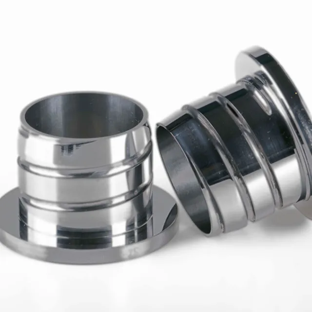


Stainless Steel Pipe Connector | Build to Print CNC
Place of Origin : XiaMen, China
Type : Broaching, DRILLING, Etching / Chemical Machining, Laser Machining, Milling, Other Machining Services, Turning, Wire EDM, Rapid Prototyping
Micro Machining or Not : Micro Machining
Model Number : CNC-11
Brand Name : High End OEM Service
Materials Avaliable : stainless steel,Aluminum, Copper
Manufacture Processing : External/Internal/Thread Turning Tool, Tooling/Molding Stamping,
Surface Treatment : Anodizing, Sandblasting, etc,
Quality control : 100% Inspection Berore Shipment
Facility Certificates : ISO9001:2015/IATF6949/ROHS/SMETA/ISO14001
Accept Drawing : PDF file,JPG,2D file,3D file,etc
Industrial Experience : 25+ Years
MOQ : Small Orders Accepted
OEM Service : Support Full Customizing
Processing Tolerance : +/- 0.05mm
Description
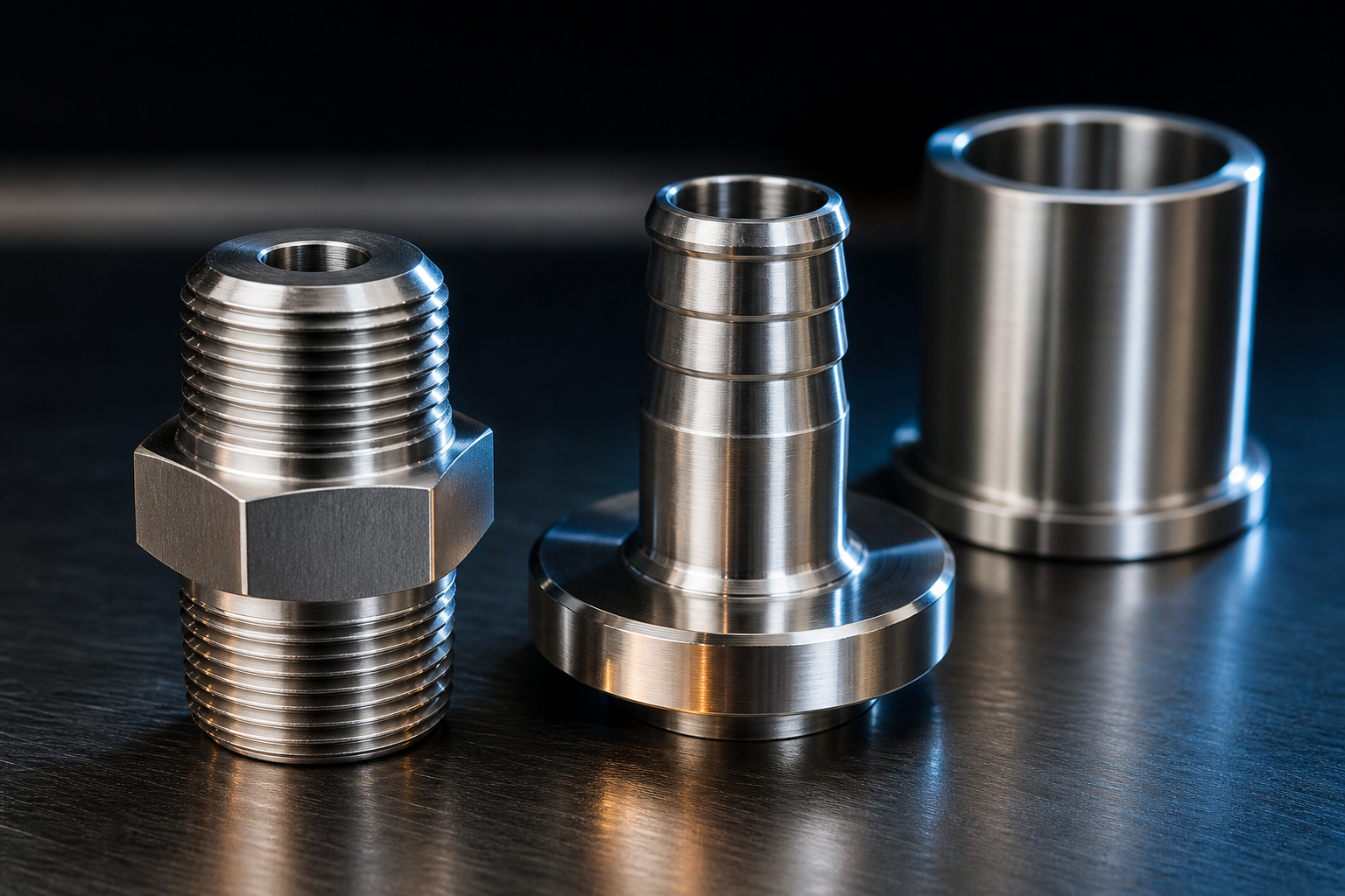
CNC Machining · Fluid Connectors
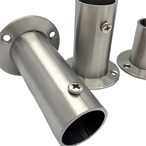
Custom CNC-Machined Stainless Steel Pipe Connector
Threaded, flanged, barbed or weld-prep ends machined from bar to your drawing. Model reference CNC-11.
- Stainless 304 / 316L
- +/- 0.05 mm general
- Two different ends
- Small orders accepted
- End form is a drawing decision — the two ends need not match.
- Seal face, thread and bore are called out separately from the general tolerance.
- No pressure rating is published: containment follows the joint, not the alloy.
What this part is, and what it is not
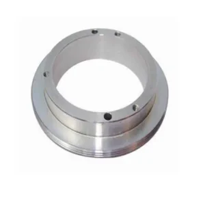
A machined stainless connector joins two elements of a fluid circuit: a tube to a port, a hose to a tank outlet, a sensor to a manifold. Both ends are produced from your drawing, so the part is defined by its interfaces rather than by a stock size.
Five interfaces decide whether the joint works: the end form, the thread, the seal face, the bore and wall, and the material condition. Each is a separate tolerance with its own inspection gate, and each is specified on the drawing rather than assumed from the catalogue reference.
Three things this product is not. It is not a stocked fitting catalogue — there is no size list to order from. It is not pressure-rated as a loose part — containment is a property of the assembled joint and the test performed on it. And it is not made pressure-tight by the alloy: a 316L body with an out-of-square seal face leaks exactly like a 304 one.
What the shop contributes is the machining sequence that makes the thread, bore and seal face concentric, and an inspection plan that checks each interface against the drawing instead of reporting a single final pass.
Specification
Six parameters are fixed for this item and six are set by your drawing. Keeping the two apart is what stops a quotation being built on an assumption.
- Model reference
- CNC-11 Fixed
- Base materials
- Stainless steel, aluminium, copper Fixed
- General machining tolerance
- +/- 0.05 mm on general dimensions Fixed
- Surface treatment options
- Anodising (aluminium), sandblasting; stainless fluid service uses passivation Fixed
- Accepted drawing formats
- PDF, JPG, 2D and 3D files. The dimensioned 2D drawing is the controlling document. Fixed
- Order quantity
- Small orders accepted Fixed
- End form, each end
- Threaded, flanged, barbed or weld preparation Drawing
- Thread specification
- Series, nominal size, pitch, tolerance class, hand, depth, inspection datum Drawing
- Seal geometry
- Face, groove or taper; flatness; finish; squareness to the thread axis Drawing
- Bore and wall
- Diameter and tolerance, roundness, concentricity, minimum wall at the thinnest section Drawing
- Material grade and certificate
- Grade named on the drawing; certificate requested on the order Drawing
- Pressure rating
- Not published for this part family — follows the specified joint and its proof test Drawing
End forms and where each one seals
The end form decides where the seal happens and what carries the load. Only a tapered thread seals on the thread itself; everything else carries clamp load and seals somewhere specific.
1Taper thread
Seals on the thread itself, by flank interference, with sealant filling the helical gap.
Drawing must fix: thread form, pitch diameter, engagement length, wrench feature
2Parallel thread, face seal
The thread only clamps. The seal is a gasket or bonded washer compressed on a flat shoulder.
Drawing must fix: seal face squareness, flatness, finish, seat undercut
3Flanged
A gasket or O-ring is compressed between two flange faces; bolts carry the load.
Drawing must fix: face flatness, groove concentricity, bolt circle, face finish band
4Barbed spigot
The hose wall is compressed onto the barb crests by an external clamp.
Drawing must fix: crest diameter, barb profile, lead-in chamfer, wall under the root groove
5Weld preparation
Sealed by fusion. There is no elastomer and no clamp load to control.
Drawing must fix: bevel angle, root land, gap, post-weld cleaning and passivation
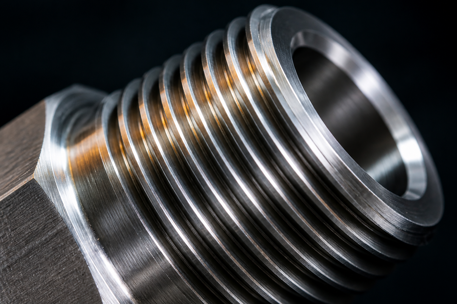
The five interfaces
One part, five separately specified zones. Only the end form is visible in a catalogue photograph; the four that decide whether the joint holds are inside the drawing.
| Interface | What it controls | What the drawing must state |
|---|---|---|
| 1. End form | How the part attaches and how load is carried | Type on each end, nominal size, engagement, wrench feature, orientation |
| 2. Seal face | Whether the joint seals, and at what clamp load | Face, groove or taper; flatness; finish band; squareness to the thread axis |
| 3. Bore | Flow area and whether a probe or mating tube passes | Diameter and tolerance, roundness, straightness, concentricity, burr limit |
| 4. Wall and body | Strength and stiffness under clamp load | Minimum wall at the thinnest point, body across flats, relief, thread run-out |
| 5. Material and surface | Corrosion resistance, galling, cleanliness of the wetted path | Grade and condition, stock form, passivation, freedom from free iron |
Material and condition
The word stainless describes a family, not a specification. Three decisions have to close before the material is defined: grade, stock condition, and whether the part will be welded.
| Decision | Why it matters to the joint | Where it bites |
|---|---|---|
| Grade | Sets corrosion resistance in the actual medium, not in general | Chloride service or a stagnant wetted path where a general-purpose grade pits |
| Stock condition | Cold-drawn bar machines cleaner and holds a better bore than hot-rolled or forged stock under the same cut | Finish inside a small bore, and dimensional drift between the first and last part of a bar |
| Free-machining grade or not | Improves chip control and finish, but carries a corrosion and weldability penalty | A part specified for machinability that then has to be welded |
| Galling resistance | Austenitic stainless cold-welds against itself under load; a thread can seize before it seats | Repeated make-and-break joints, and first assembly in the field rather than at the bench |
| Weldability | Decides whether a weld-preparation end suits the chosen grade | A weld end on a grade needing a filler and post-weld treatment nobody budgeted |
How it is made
Turned first, milled second. The sequence is not a preference: concentricity between the thread, the bore and the seal face is created by the setup, not inspected into the part afterwards.
Bar prep
Cut, faced and centred. Establishes the first datum and removes the saw burr.
First turning
OD, bore, seal face, thread and grooves in one chucking. Every feature shares one axis.
Second turning
Part reversed for the other end, only where the drawing states a permissible runout.
Milling / mill-turn
Cross holes, wrench flats and bolt circles, after the turned features are finished.
Deburr
Bore transitions, thread starts, groove edges. A burr surviving here becomes a leak path.
Passivate, inspect, pack
Free iron removed, gates checked per interface, threads protected in transit.
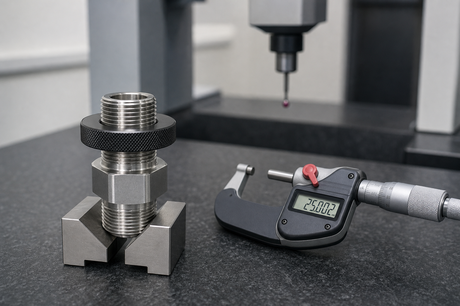
Inspection, one gate per interface
An inspection plan names the characteristic, the method, the record and the rate. A claim that names only a percentage names none of those.
| Interface | Characteristic | Method |
|---|---|---|
| End form | Thread form, pitch diameter, engagement, hand | Ring or plug gauge; thread measuring system where a value is reported |
| End form | Barb crest diameter and groove position | Micrometer or profile measurement across crests |
| Seal face | Flatness and squareness to the thread axis | Indicator on a surface plate against the nominated datum; optical flat where tight |
| Seal face | Finish in the seal zone | Stylus roughness measurement in a stated direction, with cut-off recorded |
| Bore | Diameter, roundness, straightness | Bore gauge at defined stations, three orientations, values per station |
| Bore | Concentricity to the drawing datum | Mandrel and indicator, or coordinate measurement |
| Wall and body | Thinnest wall section, body across flats, length | Micrometer and calliper at points identified on the drawing |
| Material | Grade of the stock actually used | Certificate review, plus positive material identification where required |
Where it is used
Fluid circuits that need a machined interface rather than a cast or stocked fitting. Suitability for a specific medium, pressure or cleanliness class is confirmed per project against the alloy and the joint design.
- Hydraulic power units
- Instrumentation panels
- Water treatment skids
- Chemical dosing lines
- Cooling circuits
- Compressed air distribution
- Process skids
- Tank outlets
- Test benches
- Marine deck systems
Frequently asked questions
Can you machine a stainless steel pipe connector from a drawing?
Yes. The part is quoted from a 2D drawing, a 3D model or a physical sample, with the connection interfaces, alloy and inspection requirements confirmed before tooling.
Which stainless grade should a pipe connector use?
Grade follows the fluid, the environment and the joint design. 304 covers general service; 316L is chosen where chlorides or a welded or aggressive circuit makes molybdenum content matter. The grade is fixed on the drawing, not implied by the word stainless.
Is a stainless connector automatically suitable for high pressure?
No. Pressure containment is a property of the whole joint: thread engagement, seal geometry, wall section, material condition and the test performed. No pressure rating is published for this part family; the rating follows the specified joint and its proof test.
How is the thread specified?
By thread series, nominal size, pitch, tolerance class, hand, depth and the datum the thread is checked from. A drawing that says only the nominal size leaves the fit undefined.
What tolerance applies to a machined connector?
The general machining tolerance stated for this part family is +/- 0.05 mm. Seal faces, thread engagement and bore concentricity are called out individually, because a single general tolerance cannot govern features that decide whether the joint leaks.
How do you prove the bore and seal face are correct?
The bore is checked for diameter, roundness and straightness; the seal face for flatness, surface finish and squareness to the thread axis; the thread with a ring gauge or thread measuring system. Each is recorded against the drawing.
Do you supply material certificates?
A material certificate for the heat used is supplied when the order asks for one. What the certificate proves is the chemistry and mechanical properties of the stock, not the dimensional conformity of the finished part.
What causes a leak at a machined connector?
Most leaks trace to the seal interface rather than the thread: a face that is not square to the thread axis, a surface finish that prevents the seal seating, insufficient or uneven clamp load, or a burr at the bore transition.
Can the connector be supplied with a flange or a hose barb instead of a thread?
Yes. End form is a drawing decision: threaded, flanged, barbed or weld preparation, and the two ends need not match. Each end form has its own critical features and inspection method.
What should I send for a connector quotation?
A 2D drawing with the interface callouts and datums, a 3D model if available, the alloy and condition, the fluid and service environment, the expected pressure and temperature, the required inspection and documentation, and the annual quantity.
Have a connector to develop?
Send the drawing, the alloy, the mating interface and the service conditions. The review covers the five interfaces on this page and returns a list of anything the drawing leaves open before a price is quoted.
Request a Connector Quote2D drawing, 3D model or sample · alloy and condition · medium, temperature and pressure · inspection and documentation level
Related
Pressure rating, leakage rate and certificate list are not published on this page, because each follows the specified joint, the test performed and the order documentation rather than the part family. Dimensions, thread and seal geometry are confirmed against the customer drawing.