Packaging · Thin-Wall Injection Moulding
Thin-Wall Packaging Injection Molding: The Interfaces Decide
A thin-wall packaging part rarely fails in the middle of a wall. It fails at the rim where the lid seats, at the base radius where it warps, at the stack step where the load transfers, and at the gate where the part leaves the core. Thickness is the number everybody measures; the interfaces are what the buyer actually experiences.
Written for buyers and packaging engineers specifying containers, tubs, cups, trays and lids. Where a figure would be a capability claim we cannot verify for a given part, this page states the condition to be checked instead of asserting the result.

What This Page Is, and What the Pages Beside It Already Answer
The site already carries both of those. There is a long technical guide on length-to-thickness ratio, filling, gating, venting, cooling and defect mechanisms, and there is a general injection-moulding service page covering capability, materials and the DFM workflow. Between them they answer why a thin wall is hard to fill. Neither answers the question a packaging buyer actually arrives with, which is will this container hold my product, take my lid, stack in my pallet and be legal in my market.
That second question is not a flow question. It is an interface question, and it is the reason this page exists as a separate document rather than another chapter on the flow guide. A part can fill beautifully and still fail, because the lid leaks, or the base rocks on a filling line, or the stack collapses in the top layer of a pallet, or the declaration the retail buyer asked for cannot be issued.
"Thin Wall" Is a Ratio and a Function, Not a Millimetre Value
The older version of this page defined thin-wall moulding as producing parts with a wall of 0.5 mm or less. That sentence has been removed, because it is wrong in both directions. It excludes large tubs with 0.9 mm walls that are genuinely difficult, and it includes small pots with 0.5 mm walls that fill comfortably because the flow is short. The number alone does not predict anything.
| Definition | What it captures | Where it breaks down |
|---|---|---|
| Absolute thickness | A single drawing value that is easy to write on a purchase order | Ignores part size entirely; a common value is trivial on a sauce pot and severe on a tray |
| Length-to-thickness ratio | The actual difficulty: distance travelled through a narrow channel | Needs a gate position to compute, so it cannot be evaluated before the tool layout exists |
| Functional definition | What the wall has to do — hold 500 ml, carry a stack, take a snap bead, survive freezing | Cannot be checked without the pack and its use, so it needs the buyer's input, not the supplier's |
In practice all three are used together and the order matters. The functional requirement sets the target; the ratio tells you whether the target is reachable in that resin from that gate; the absolute number is what finally appears on the drawing and on the inspection report. Starting from the third one, as most enquiries do, produces a number that either over-engineers the part or buys a tool that cannot fill it.
A Packaging Part Is Four Interfaces and One Declaration
| # | Interface | What decides whether it works | How it is proved |
|---|---|---|---|
| 1 | The product | Fill volume and headspace, filling temperature, fat and acid content, contact time, storage and reheat conditions | Fill trial under the real conditions, then the migration test set that matches them |
| 2 | The closure | Seal geometry, bead engagement, rim flatness and width, closing force, film seal window | Leak or decay test on the assembled pack, plus lid removal force |
| 3 | The stack | Where the load path runs, nesting interference, assembled height, pallet pattern | Top-load test on the assembled pack, and a real pallet stack |
| 4 | The mould | Draft, ejection area, shrink onto the core, gate vestige | Weight per cavity, ejection marks, dimensional report at trial |
| 5 | The declaration | Resin grade, additives and colour, article structure, conditions of use, destination market | Supplier declarations for each input, and article-level testing where required |
The order is deliberate. Most packaging projects start at number two, because the lid is the part everyone can see and the leak is the failure everyone fears. But a leak is often number one expressing itself: a hot-fill container that has shrunk after filling will not take its lid the way it did at room temperature, and no amount of lid tuning recovers that.
Which Packaging Parts This Route Suits, and Which It Does Not
The families below are organised by the geometry that decides them, not by product category. Two cups in the same category can land on different sides of the line if one has a moulded thread and the other has a plain wall.
| Family | Typical route | The feature that decides it |
|---|---|---|
| Rectangular meal and takeaway containers | Injection, usually with a separate or hinged lid | Rim flange with a snap bead, stacking step, integral divider walls |
| Round tubs and pails | Injection | Outward rim bead that the lid skirt engages under, and a deep straight side |
| Sauce and portion pots | Injection, sometimes thermoforming | Small size and high cavity count; film seal land on the rim |
| Yogurt, dessert and dairy cups | Either, decided by features | Film seal land and print quality favour sheet; a moulded rim bead favours injection |
| Prepared-food and meat trays | Thermoforming, mostly | Large area, shallow depth, no integrated closures |
| Lids and closures | Injection | Plug seal or bead, flatness across the whole face, IML where required |
| Non-food industrial packaging | Injection | Wall thickness set by drop and stack loads rather than by fill time |
Two cautions on using that table. First, it is a default, not a rule — a shallow tray with a snap-on lid becomes an injection part, and a deep cup with no features can be thermoformed. Second, the route decision changes the drawing. A thermoformed tray is designed from a sheet with a known gauge and a known draw ratio; an injection-moulded tray is designed as a solid with a wall map. Redrawing for the other route is not a translation, it is a new design.
The Wall Map: Why One Thickness Number Is Not a Specification
The reason this matters commercially is that the first inspection usually goes wrong here. A buyer measures the rim with an ultrasonic gauge, gets 0.85 mm against a 0.7 mm callout, and concludes the part is out of specification. It may not be: the rim is a bead, not a wall, and no drawing ever said the 0.7 applied to it. The argument that follows is about the drawing, not about the moulding.
| Zone | What governs its thickness | How to write it on the drawing |
|---|---|---|
| Side wall, mid-height | Flow length and required stiffness; the primary fill path | Toleranced wall, measured at defined stations |
| Base panel | Top-load stiffness for the stack, and flatness for stability | Toleranced wall plus a flatness callout on the seating ring |
| Base-to-side radius | Flow restriction, stress concentration, ejection stress | Nominal reference — a nominal thickness here is not a specification |
| Rim and bead | Bead engagement and seal geometry, not flow | Datum-defined profile, with the seal land toleranced as a face |
| Gate area | Gate size and packing; often locally thicker by design | Excluded from the wall callout, with the vestige specified separately |
| Ribs and divider walls | Stiffness per gram; sink risk on the opposite face | Own thickness, expressed as a fraction of the nominal wall |
How the wall is actually measured
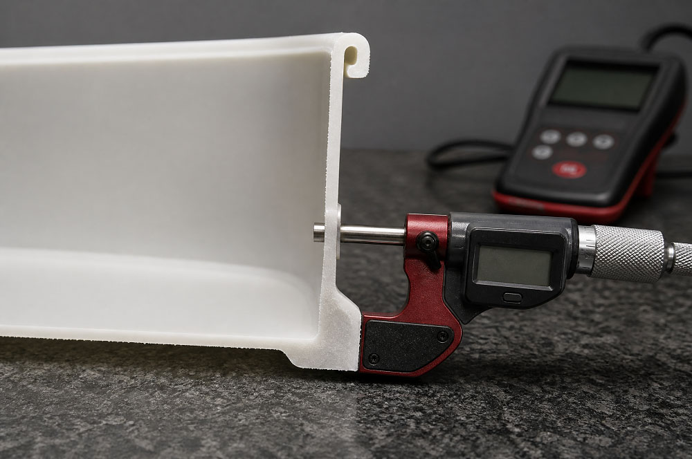
An ultrasonic wall-thickness gauge is the production instrument: fast, non-destructive, and workable on a curved surface with the right transducer. It has two weaknesses worth knowing before a dispute. It needs the correct speed of sound for the specific resin, and the figure drifts between grades and with glass or mineral filler. And it reads the first strong echo, which on a rib, a radius or a double wall can be the wrong surface entirely.
The referee method is sectioning. Cut the part at defined stations — a quadrant of the side wall at three heights, the base centre, the corner radius, the rim — mount it, and measure the cut edge under magnification. It is slower and it destroys the sample, which is exactly why it is used at trial and at first article rather than at every batch. A programme that only ever uses the gauge has no independent check on the gauge.
Resin by Function: What Each Family Buys and What It Costs
| Resin | What it buys | What it costs |
|---|---|---|
| PP homopolymer | Stiffness, heat resistance, low density, low cost per part | Brittle at low temperature; high and predictable shrinkage; hazy unless clarified |
| PP impact copolymer | Toughness at chill and freezer temperatures; survives drops and handling | Lower stiffness and heat resistance than homopolymer, so the wall or the rib design has to compensate |
| PP random copolymer | Better clarity and a lower, wider sealing window for film lids | Lower stiffness and a lower softening point, which limits hot-fill use |
| HDPE | Chemical resistance, toughness, good flow in thin sections | Lower stiffness than PP, so top load falls off quickly with wall reduction |
| GPPS and HIPS | Clarity (GPPS) or toughness and opacity (HIPS); low shrinkage and easy dimensional control | Poor solvent and fat resistance; brittle; not suitable for hot fill |
| PET and rPET | Clarity, gas barrier, established recycling stream | Moisture-sensitive, needs drying; crystallinity has to be controlled; reheat behaviour differs for rPET |
| PLA and other compostables | A compostability claim, where the destination market has the collection route to support it | Low heat resistance, moisture sensitivity, and a much shorter processing window |
What melt flow rate does, and what it does not
Melt flow rate is measured under a fixed load and temperature — for polyolefins the familiar condition is 230 °C at 2.16 kg — and it ranks resins by how freely they flow. In thin-wall work it is the first filter, because a grade that cannot flow will not fill no matter how the tool is designed.
It is a poor second filter. Flow is usually bought by lowering molecular weight, and molecular weight is where toughness, stress-crack resistance and melt strength come from. A high-flow grade that fills a difficult part and then cracks at the hinge in a chilled distribution chain has not solved the problem, it has moved it downstream. This is why the resin is chosen against the service requirement first and the flow requirement second — never the other way round.
The Food-Contact Declaration: What a Moulder Can Sign and What It Cannot
The legal structure differs between the two markets this page is written for, and the differences change what a buyer has to ask for.
| European Union | United States | |
|---|---|---|
| Framework | Regulation (EC) No 1935/2004, which requires materials not to transfer constituents in quantities that endanger health or alter the food | Food-additive regulations under 21 CFR Part 177, plus effective food-contact notifications for substances not already listed |
| Plastics instrument | Regulation (EU) No 10/2011: a Union list of permitted substances, specific migration limits, and an overall migration limit of 10 mg/dm² of contact surface or 60 mg/kg of food | 21 CFR 177.1520 for olefin polymers, which sets permitted base polymers and specifies extractables limits and conditions of use |
| Documentation | A declaration of compliance is required at every stage of production and marketing except retail, supported by the underlying test data | A letter of guarantee or compliance statement from the supplier, citing the applicable regulation or notification |
| What sets the test | Food simulants and test conditions selected from the food type, contact time and contact temperature | Conditions of use defined in the regulation, matched to the actual application by the user |
Read the first row of that table again, because it contains the sentence the whole chapter turns on: 10 mg/dm² of contact surface. That is a limit on the finished article. It cannot be demonstrated on a pellet. Between the pellet and the article sit the colourant, the masterbatch carrier, any additive package, the label, the adhesive on the label, and the sealing film if there is one. Each of those is a separate input with its own compliance position, and any one of them can fail a migration test that the base resin would pass on its own.
What the moulder contributes
- Material identity. The exact grade, the supplier, and the declaration that came with it — not a generic "PP" statement.
- Additive disclosure. Colourant and masterbatch supplier and their declarations, including the carrier resin, which is often overlooked because it is a small fraction.
- Process statement. No prohibited substances on the machine, regrind policy and the maximum regrind fraction if regrind is used at all, and the cleaning regime between materials.
- Article structure. What the finished pack consists of — body, lid, label, film — so that the buyer can see which inputs still need their own declaration.
What the moulder cannot contribute
It cannot state that the article is suitable for a specific food at a specific temperature for a specific duration, because that conclusion comes from migration testing under conditions of use that only the brand owner knows. It cannot state that the pack is microwave-safe, because that is a claim about the finished pack and the way a consumer will use it. And it cannot state that the pack is recyclable in a given country, because recyclability is a property of the collection and sorting system as much as of the material.
Recyclability Is a Claim About the Whole Pack, Not About the Resin
The regulation was published in January 2025 and has applied generally since August 2026, with the performance grading of recyclability following on a later timetable. The practical consequence for a packaging project is that material choice is no longer only a cost and performance question: a pack that cannot be sorted into an existing stream is a compliance problem, and the design decisions that determine sortability are made at the drawing stage.
| Decision | Who makes it | What it changes |
|---|---|---|
| Base resin and colour | Buyer, with the moulder | Whether the pack enters a mono-material stream; carbon black defeats near-infrared sorting |
| Barrier layers and coatings | Buyer, by specification | Whether the pack counts as mono-material or as a multi-material structure |
| Label material and adhesive | Buyer, or the IML supplier | A PP label in an PP body is compatible; a paper or metallised label is a contaminant |
| Wall thickness and weight | Moulder, within the flow limit | Material per pack, and the mechanical yield of the recycling process |
| Collection and sorting | Nobody in this chain | Whether the pack is actually recycled, as opposed to being recyclable in principle |
The row that surprises buyers is the last one. Recyclability is a design property; recycling is a system outcome. A pack can be perfectly designed for recycling and still go to energy recovery in a municipality that does not sort that polymer. A supplier who claims a pack is "recycled" because it is mono-PP has made a claim about infrastructure it does not control.
The Lid Interface: Why Leaks Are a Stack-Up, Not a Tolerance
This is the single most expensive confusion in packaging projects, because it sends buyers looking for a tolerance to tighten when the real answer is a feature to redesign. Four closure systems behave in four different ways, and only one of them is a mechanical snap.
| System | How it holds | How it seals | Typical failure |
|---|---|---|---|
| Snap-over-flange with bead | Lid skirt hooks under an outward rim bead | Only if a land or plug feature is also present; the bead alone is retention | Lid holds but weeps; the bead is blamed for a seal that never existed |
| Plug seal | Friction and a bead interfering with the bore | Radial interference between the plug skirt and the container's inner wall | Over-interference bows the skirt, opening a gap at one point of the circumference |
| Liner or gasket seal | Thread or clamp | Compression of an elastomer against the rim plane | Rim flatness, not rim diameter; a warped rim leaks whatever the elastomer |
| Heat-sealed film | Nothing mechanical | A seal layer fused to the flange under pressure, temperature and dwell | Product on the flange, or a flange too narrow for the seal bar |
The stack-up that decides whether a pack is tight
Take a snap lid on a round tub. Whether the pack seals depends on the rim's outer diameter, the rim's flatness, the width of the sealing land, the height of the bead above the land, the lid's skirt diameter, the bead engagement depth, the lid's own flatness across the seal face, and the force the closing equipment applies. That is seven variables from two tools and one machine, and they all move with shrinkage.
Tightening any single one of them in isolation usually makes the pack worse. Reduce the skirt diameter to increase interference and the skirt bows outward between the bead and the top face, lifting the seal land at the point of maximum bow. Increase the bead engagement and the lid becomes hard to close, so the closing equipment distorts the rim instead. The fix is almost always to give the seal a defined feature with its own datum, and to let the retention bead do only the job of retention.
Film seals are a system, not a surface
Where the lid is a heat-sealed film, the flange is the seal. Its width sets how much seal area exists; its flatness sets whether the seal bar can apply uniform pressure; its cleanliness sets whether anything is trapped in the joint; and its resin sets the temperature window, because the seal is formed by melting the film's seal layer into the flange surface. A wide sealing window is the outcome of matching film, flange and sealer — it cannot be bought by specifying a tighter tolerance on the flange diameter.
This is why a film seal is never proved on a tub alone. The film structure, the seal bar geometry, the pressure and dwell settings and the filling line's flange condition all belong to the same test, and the test has to be run on a filled pack with the real product, because a splash of oil on the flange will defeat a seal that passed on an empty one.
'Stacking and Nesting: Two Different Tests, Often Confused
Where the load actually travels is the part most drawings never say. In a well-designed tub the base of the upper container lands on a stacking step in the rim of the lower one, so the load passes through the side wall column of each container in turn. In a badly designed tub the upper base lands on the lid, and the lid — which is a thin disc with a skirt, designed to be removed by hand — becomes a structural member it was never meant to be.
| Test | What it measures | What it does not |
|---|---|---|
| Top load on an empty container | The container's own column strength between platens | Anything about the assembled pack, or about the lid |
| Top load on the filled, closed pack | The real load path, including whatever the lid is doing | Long-term behaviour, because it is usually a short-duration test |
| Pallet compression over time | Creep, and how the stack behaves with the outer cartons removed | Nothing about single packs, and it is expensive to run |
The distinction matters because plastic creeps. A container that carries 20 kg for a minute and a container that carries 8 kg for three months are not making the same claim, and the second is what a warehouse in summer actually demands. Temperature belongs in the test too: a polypropylene stack that is stable at 20 °C loses stiffness as it warms, and a trailer in August is not a laboratory.
Nesting is a logistics decision made at the drawing stage
Empty containers ship as a nested column. The taper that lets them nest is the same taper that lets them release from the core, which is why a change of a fraction of a degree can move both the moulding and the freight cost. Nesting ratio — how many containers fit in a given height — drives carton size, pallet count and container load, and it is decided long before anybody prices the freight.
The counter-requirement is de-nesting. A filling line has to separate one container from the column at speed, and if nesting is too tight the line jams, or the separation mechanism crushes the rim. If it is too loose the column collapses in transit. There is a band, and it is narrow, and it is set by the interference between the outer wall of one container and the inner wall of the next — not by the nominal taper angle alone.
Demoulding a Thin Wall: Why the Weakest Moment Is the Last One
The common belief is that thin walls need less draft because they are short. The opposite is true in practice: a thin wall has little rigidity, so it deforms rather than slides if it is gripped, and a tall thin side with no draft will scuff, stress-whiten or tear on the way off. Draft is what converts friction into sliding.
| Decision | What it controls | What goes wrong if it is wrong |
|---|---|---|
| Draft on the core | Whether the wall slides or is dragged | Scuffing, stress whitening, and a wall that thins at the base as it is stretched off |
| Ejection method | Where the force is applied | Ejector pins on a thin base leave witness marks and dish the base; a stripper ring spreads the load |
| Ejection temperature | Whether the part is still soft when pushed | A base that rocks, a rim that is oval, a wall that bows and stays bowed |
| Core cooling | How quickly the inside of the wall sets | A wall that is surface-set but molten at the core, which distorts on ejection and creeps afterwards |
For a container, the part shrinks onto the core because the core is on the inside. That single fact drives most of the tool design: the core has to be tapered and polished in the draw direction, the base needs enough radius to survive being pushed, and the ejection system has to apply force around the base perimeter rather than at its centre. A stripper ring, or air assist behind the base, is the usual answer for a thin-wall tub; ejector pins are the usual cause of a base that no longer sits flat.

Gating and the Vestige Nobody Budgeted For
Flow length is the constraint that decides whether the part fills at all, and the gate position is the only variable that changes flow length without changing the part. Move a gate to the centre of a rectangular tray and the longest path halves; the flow length that made the part impossible becomes comfortable. That is why gate layout belongs in the DFM review and not in the toolmaker's discretion.
| Gate | Buys | Costs |
|---|---|---|
| Centre gate on the base | Radial balanced flow, no weld line on a round part, short flow | A visible vestige on the base — which is also the stacking face |
| Edge gate | Flow from the perimeter inward, useful where the base must stay clean | Long flow path on a large part, an unbalanced fill, and a mark on the side wall |
| Hot tip | No runner to trim, short cycle, high cavity counts | A small gate mark plus a frozen pip; drool and stringing if the tip temperature drifts |
| Valve gate | Clean vestige and positive shut-off, best control on multi-cavity balance | Tooling cost and maintenance; a valve pin leaves its own small disc |
| Tunnel or submarine gate | Automatic degating on ejection | A witness mark on a side face, and a gate that can shear and block |
Gate freeze and packing
A thin-wall gate has to be large enough not to freeze before the cavity is packed, and small enough not to leave a mark that has to be trimmed. That window is narrower than it looks. If the gate freezes early, the part is under-packed: it shrinks more, it weighs less, and the weight varies from cavity to cavity. The symptom appears as a sink at the gate, a base that rocks, or a rim that is oval — three different complaints, one cause.
Which is why part weight per cavity is the most useful single number in a packaging trial. It is cheap to measure, it is sensitive to gate freeze, to hot-runner imbalance and to cooling differences, and it moves before the defects become visible. A tool that produces parts of visibly equal quality but uneven weight is a tool that will produce scrap as soon as the ambient conditions change.
Cooling: Where the Cycle Actually Goes
A container is cooled from both sides: the cavity side cools the outside, the core cools the inside. For a cup or a tub, the core is a slender steel form inside the part, and getting water to its tip is the hardest cooling problem in the tool. A simple straight bubbler cools the lower part of the core well and the tip poorly, which is exactly where the base sits. Baffles, bubblers and, increasingly, conformal inserts in the core are all attempts to move coolant closer to the base.
| Region | Why it lags | What it causes if it lags |
|---|---|---|
| Base centre | Furthest from any cooling channel; the thickest section in most containers because it carries the stack load | Base that rocks, dished or domed base, sink on the underside |
| Base-to-side radius | Thick, and in the shadow of both the core tip and the cavity wall | Local shrinkage that pulls the wall in, reducing the stack step and changing nesting |
| Rim bead | Thick by design, and at the edge of the cooling circuit | Ovality, which changes lid fit around the circumference rather than uniformly |
| Side wall | Thin, so it sets quickly — but it is also where differential cooling shows first | Bowing toward the hotter side, and a taper that is no longer the drawn taper |
Why cycle claims need three numbers
A cycle time quoted on its own is meaningless, because it can always be shortened by accepting more scrap, a heavier part, or a smaller cavity count. The three numbers that make a cycle claim comparable are the cycle time, the number of cavities, and the part weight with its tolerance. Seconds per cycle divided by cavities gives seconds per part; multiply by the cavitation and the uptime and you get capacity. A quote that gives only the first number is not a capacity statement.
In-Mould Labelling in a Thin Wall
The mechanical sequence is straightforward: a printed film with a heat-activated lacquer on the reverse is picked from a magazine, presented into the open cavity, held against the wall by vacuum or static, and the mould closes onto it. On ejection the label is integral. What is not straightforward is what happens to the wall behind it.
| Effect | Mechanism | What to do about it |
|---|---|---|
| Local cooling changes | The film insulates the wall from the cavity steel, so that region cools more slowly and shrinks differently | Expect a different local wall and a possible step at the label edge; agree the tolerance before trial |
| Cycle penalty | Label placement and pick-up take time inside the cycle | Cost it as part of the cycle, not as a separate decoration charge |
| Registration tolerance | The label position depends on placement accuracy, not on print accuracy | Specify registration against a moulded feature, and give it a realistic band |
| Material composition | The pack is now body plus film plus lacquer plus ink | Use a compatible label film if recyclability matters; a paper label in a PP body is a contaminant |
| Corner and radius behaviour | Film does not stretch like melt; it wrinkles where the geometry turns tightly | Keep the labelled area away from tight radii, or accept a design feature that hides the turn |
The recyclability row is the one that gets decided last and costs most to change. A mono-material PP pack with a PP label is a mono-material pack. The same pack with a paper label, or a metallised film, or a full-body sleeve in a different polymer, is a multi-material pack — and the design-for-recycling assessment changes accordingly. That decision is made when the artwork is commissioned, which is usually months before anybody asks the moulder about materials.
Defects, and the Variable That Actually Controls Each One
| What you see | What is usually happening | The variable that controls it |
|---|---|---|
| Short shot at the last corner | The flow front froze before the cavity filled; the corner is the furthest point from the gate | Gate position and size, injection speed, venting at the corner, resin flow |
| Base that rocks on a flat surface | Differential cooling or packing between the base centre and its rim | Core-tip cooling, packing pressure and time, ejection temperature |
| Lid that does not seat | Rim ovality, or a bead that sits at the wrong height after shrinkage | Rim bead geometry, cavity balance, mould temperature uniformity around the circumference |
| Flash along the flange edge | Cavity pressure has deflected the plates or opened the shut-off | Tool stiffness and support, clamp force, injection pressure profile |
| Sink at the gate | The gate froze before the section was packed | Gate cross-section, hold time, melt temperature |
| Stress whitening at a hinge | The living hinge was flexed while still cold, or the melt orientation across it is wrong | Hinge geometry, gate position relative to the hinge, ejection temperature |
| Wall that scuffs or tears at the base | The part gripped the core and was dragged off | Core draft, core polish, ejection area, ejection temperature |
| Weight varying between cavities | Unbalanced melt delivery, or gates freezing at different times | Hot-runner balance, nozzle tip temperatures, cooling balance |
| Stringing or drool at the gate | The melt is too fluid at the tip, or the tip is too hot | Hot-tip temperature, decompression, cooling at the gate |
| Label wrinkled at a corner | Film cannot stretch to follow the geometry | Label position relative to radii, film gauge and stiffness, vacuum hold |
Two of these rows deserve a warning because they are routinely misdiagnosed. The warped base is usually blamed on the resin, and the answer is usually thermal: the base is the last region to cool and the hardest to pack, so it is where any imbalance accumulates. And the non-seating lid is usually blamed on the lid tool, when the cause is ovality in the container's rim — which is a difference of 0.1 mm around a circumference, invisible to the eye and obvious to a leak test.
Injection Moulding or Thermoforming: How the Decision Actually Goes
| Question | Points to injection moulding | Points to thermoforming |
|---|---|---|
| Are there integrated features? | Snap beads, threads, hinged lids, divider walls, ribs, tamper tabs — all moulded in one shot | Features have to be added, or formed poorly by the stretch |
| How deep is the part relative to its opening? | Depth is a flow-length question, solved with gating | Deep draws thin the wall unevenly, especially at corners and the base |
| How controlled must the wall be? | Wall is set by the cavity, so the map is repeatable | Wall is set by sheet gauge and stretch, so thickness varies by position by design |
| What is the annual volume? | Tooling is higher, so volume has to amortise it; high cavitation pays it back quickly | Lower tooling and shorter lead time suit lower volumes and design iteration |
| How big is the part? | Clamp tonnage and tool size grow with projected area | Large, shallow parts are thermoforming's natural territory |
There is also a materials dimension. Thermoforming starts from sheet, so the sheet can be multilayer — a barrier layer inside a structural skin, or a seal layer on one face. Injection moulding starts from pellets, so a multilayer structure means co-injection or an added step. Where barrier is the requirement, that can settle the route before any of the five questions above.
What to Measure, and on Which Sample
| Measurement | Sample state | What it catches |
|---|---|---|
| Wall map at defined stations | As moulded, after 24 hours | Fill problems, gate freeze, cooling imbalance; shrinkage continues for a period after ejection, so measuring immediately is misleading |
| Sealing land flatness and rim profile | As moulded | The leak cause that a diameter measurement misses |
| Assembled height and stack step | Closed pack | Whether the load path is where the drawing says it is |
| Leak or pressure decay | Filled and closed, after temperature equilibration | Seal failures that only appear once the pack has cooled or warmed to service temperature |
| Weight per cavity | Every cavity, several shots | Hot-runner and cooling imbalance, before it becomes visible scrap |
| Top load | Filled and closed, and separately empty | Column strength versus pack strength — two different numbers |
| Migration, where required | Finished article, conditions of use | Article-level compliance, which the resin declaration cannot cover |
The 24-hour note on the wall map is not pedantry. Polypropylene continues to shrink and to relax for some time after ejection, and a part measured straight off the machine is not the part that arrives at the filling line. A first-article report that was produced within the hour can be accurate and irrelevant at the same time.
Cost Drivers, and Why Price Per Part Needs a Volume Band
| Driver | What moves it | Buyer's lever |
|---|---|---|
| Resin per part | Wall map, part volume, gate and runner loss | Accept a thinner wall where the map allows, and drop the runner with a hot runner where volume justifies it |
| Seconds per part | Cycle time divided by cavitation | Cavity count; accepting a tool sized to the annual volume rather than to the first order |
| Scrap and start-up | Process window width, which the design sets | Wider windows come from generous radii, balanced gating and realistic tolerances — all design decisions |
| Tool amortisation | Tool cost over the volume it runs | Honest annual volume; a tool sized for one order is a tool paid for by that order |
| Freight cube | Nesting ratio and carton format | Specify the nesting ratio and the pallet pattern, not just the part |
| Decoration | IML, printing, labelling, sleeving | Material-compatible label choice, which also decides recyclability |
This is why a single unit price is close to meaningless for packaging. The same drawing can be quoted at very different prices depending on whether the buyer's 200,000 pieces a year are ordered in four runs of 50,000 or in twelve runs of 17,000, because set-up, start-up scrap and colour changes are per run, not per piece. A quote should therefore come with the volume band it assumes and the order pattern it assumes.
What to Send for a Thin-Wall Packaging Quote
| Item | Why it belongs in the first message |
|---|---|
| 3D model and a drawing with the wall map | Geometry decides gate position, cavity layout and ejection; the wall map decides whether the tolerances are achievable |
| Resin grade, colour and any recycled-content requirement | Sets the flow, the shrinkage and the documentation trail; recyclate is a sourcing question before it is a moulding one |
| Fill volume and headspace | Determines the cavity, and whether the pack will be filled hot enough to change its own dimensions |
| Lid, closure or film specification | The seal is half the pack; a quote for the container alone cannot be validated |
| Food-contact market and conditions of use | Food type, temperature, contact time and destination decide which declarations are needed and which tests apply |
| Annual volume and order pattern | Sizes the tool and the cavity count, and is the difference between two very different unit prices |
| Decoration, carton and pallet format | IML needs cavity space and cycle time; the carton sets the nesting ratio the design has to deliver |
If the design is not finished, that is not a reason to wait. A reference sample, a competitor pack that works, and a statement of what the pack has to do are enough to start a DFM conversation, and starting it before the drawing is frozen is cheaper than starting after.
Where Each Question Is Answered
This page is one node in a set. Following the right one avoids reading two documents that say the same thing.
L/T ratio, flow, gating, venting, cooling, parameters and defect mechanisms in depth
The general moulding and tooling capability, materials and DFM workflow
Enclosures rather than packaging: seam stack-up, cosmetic grades and mating halves
Appliance components: bins, ducts, liners and the injection-versus-forming boundary
Where thick sections and handles make conventional packing impractical
Where a pack needs a soft-touch grip, a seal or a metal insert
Frequently Asked Questions
What is thin-wall packaging injection molding?
It is injection moulding of packaging components whose walls are thin relative to the part's size and flow length — typically containers, tubs, cups, trays and their lids. The distinguishing problem is not the number on the drawing but the fact that the melt has to travel a long way through a narrow channel before it freezes.
Is there a standard wall thickness for thin-wall packaging?
No. Feasibility depends on the resin, the flow length from gate to the last point to fill, the geometry, the cooling, and the machine's speed and pressure. A thickness that is routine in a small sauce pot can be impossible in a large tray in the same resin.
Which is better for packaging, injection molding or thermoforming?
They suit different parts. Injection moulding suits parts with integrated features — snap beads, ribs, threads, hinged lids, divider walls — and repeatable geometry. Thermoforming suits large, shallow parts made from sheet, where tooling cost and lead time matter more than feature integration.
Does a food-contact resin make my container food-contact compliant?
No. A resin declaration covers the resin grade. The finished article adds colourants, additives, the lid, any sealing film, the processing history and the actual conditions of use — food type, contact time and temperature. Compliance of the resin does not by itself establish compliance of the container.
Why does my container leak even though the lid dimensions are in tolerance?
Because a seal is an interference between two parts, not a dimension on one part. The rim flatness, the rim width, the lid skirt diameter, the bead engagement, the resin shrinkage and the closing force all move together. Two parts that each pass their own drawing can still fail to seal as a pair.
How is wall thickness actually checked on a thin-wall container?
An ultrasonic gauge is used in production because it is fast and non-destructive, but it needs the correct speed of sound for the resin and it reads local features such as ribs and radii badly. The referee method is sectioning the part at defined stations and measuring the cut edge under magnification.
What causes a warped base on an injection-moulded tub?
Most often differential cooling or differential packing rather than the resin itself. The base is the last region to cool and the hardest to pack, so a hot ejection, an unbalanced cooling circuit or a gate that freezes early will all show up as a base that rocks.
Can a thin-wall container be made from recycled PP?
It can, subject to two conditions. The recyclate has to be characterised by grade and source so that flow and impact can be assessed, and for food contact the recycling process must be authorised for that use in the destination market. Recycled content is a supply-chain and regulatory question before it is a moulding question.
What does IML do to a thin-wall part?
An in-mould label becomes part of the wall rather than a film on top of it. It adds a thermal layer that changes local cooling and shrinkage, so the label area can pull differently from the unlabelled area. The label also becomes part of the pack's material composition, which matters for recycling.
What should I send for a thin-wall packaging quote?
The 3D model and drawing, the resin grade and colour, the fill volume, the lid or seal type, the stack height, the food-contact market and conditions of use, the annual volume with an order pattern, the decoration required, and the carton or pallet format.
Next step
Have a packaging drawing and an unresolved interface?
Send the model and whatever part of the specification is already settled. The review returns the wall map zones that need a tolerance, the seal features that need a datum, the gate position the flow length requires, and the declarations the destination market will ask for.
Request a Packaging Moulding QuoteModel and drawing · resin and colour · fill volume · lid or film · conditions of use · annual volume
How this page was written. The food-contact section describes Regulation (EC) No 1935/2004, Regulation (EU) No 10/2011 — including its overall migration limit of 10 mg/dm² of contact surface or 60 mg/kg of food and its declaration of compliance requirement — and 21 CFR 177.1520 for olefin polymers, each as published. The recyclability section refers to Regulation (EU) 2025/40, in force since 11 February 2025 and applying generally from 12 August 2026. No cycle time, minimum wall thickness, cavity count, tonnage or production capacity is claimed anywhere on this page, because each of those depends on a specific tool and a specific part.