Case Study — Medical / Surgical Instrument
316L Thin-Wall Drill Guide — Tight-Tolerance CNC
A surgical drill guide with a 0.4 mm wall, machined in 316L stainless steel across a 5,000-piece production run. The wall thickness defines the drill clearance inside the guide bore, which defines how straight the drill runs in surgery — which defines whether the screw lands where the surgeon planned.
- Part
- Drill guide
- Material
- 316L SS
- Process
- CNC + EP
- Workholding
- Soft jaws
- Lead Time
- 10 bus. days
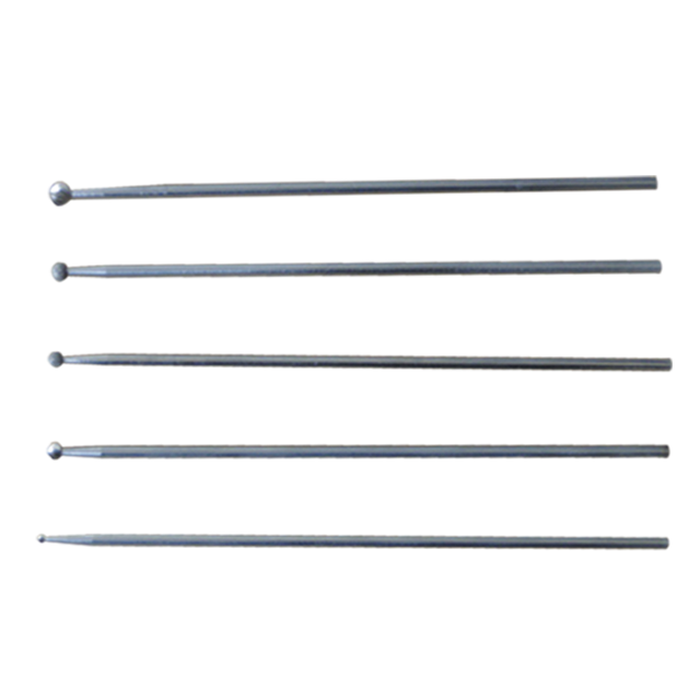
A drill guide is a positioning tool, not a structural part — the geometry exists to guide
In orthopedic trauma surgery, a drill guide sits on the bone surface and directs the drill bit to a planned position and angle before a screw is placed. The drill guide's hole position, hole diameter, and the perpendicularity of the bore to the bone-contact face all directly govern where the screw lands. A deviation of 0.1 mm at the guide translates to a mis-placed screw in the patient.
For this part — a single-barrel drill guide with a 0.4 mm wall around the guide bore — the wall itself does almost nothing mechanically. It exists only to constrain the drill bit. That changes every manufacturing decision: the wall has to be held within tolerance without being deformed by the workholding, and the bore has to be smooth enough not to deflect the drill bit as it passes through.
This page is written as an engineering record. If you are evaluating whether the same discipline can be applied to your own thin-wall surgical component, the Inspection & Verification and Final Result sections are the ones that matter.
Xiamen Goldcattle Plastic & Metal Products Co., Ltd. has been manufacturing custom precision components since 1998, operating under an ISO 9001:2015 certified quality management system.
What the customer specified on the drawing and in the RFQ
The reference everything downstream was measured against. Tolerance callouts that govern drill guide function are listed first.
- Part description
- Single-barrel surgical drill guide, trauma plating instrument family
- Material
- 316L stainless steel per
ASTM F138/UNS S31603 - Quantity
- 5,000 pieces (production run, single lot)
- Critical features
- Drill guide bore diameter and position; bore perpendicularity to bone-contact face; 0.4 mm wall around guide bore
- Dimensional tolerance
- Bore position ±0.05 mm*; wall thickness
per drawing* - Surface finish
- Internal guide bore: Ra 0.2 µm (post-electropolish)
- Inspection
- Pin gauge + optical comparator on every part; CMM on first article and every 50th part; profilometer on guide bore
- Documentation
EN 10204 3.1mill certificate;ASTM A967passivation report; dimensional inspection report per batch
* Bore position is reported as a positional tolerance on the hole axis relative to the bone-contact datum, not a profile-of-a-surface on the outer envelope. The two are not interchangeable and we report them separately. Tolerance callouts are taken from the customer drawing and confirmed at quotation.
Four constraints that determined the workholding, the cutting sequence and the finishing process
Each on its own is a known problem in drill guide manufacturing. Together, they ruled out a generic "316L parameter sheet" approach.
-
01
Problem
Wall deflection under standard clamping
A 0.4 mm wall is thin enough that a collet or standard vise applying 2 MPa or more will deform it by more than the bore-position tolerance. The deformation locks in once cutting forces are applied, and the part fails at first article inspection. The holding strategy has to be designed around the wall, not the part outline.
-
02
Problem
Chatter on the guide bore
Thin walls resonate during cutting. Chatter on the internal guide bore leaves raised ridges that scrape the drill bit as it passes through — a 5 µm ridge on the bore wall deflects the drill by tens of microns at the drill tip, which is the entire positional budget for the screw. Engagement has to stay below the resonant frequency of the wall.
-
03
Problem
Heat accumulation across a 0.4 mm wall
A 0.4 mm wall has limited thermal mass. Cutting heat accumulates faster than it conducts away, and the wall expands and contracts during the cut. Without a controlled roughing-then-finishing sequence with dwell between, the wall measures differently at the two stages and the finishing pass either removes too much material or not enough. Wall-thickness variation of ±0.01 mm on a 0.4 mm wall is ±2.5% — invisible to the eye, but the surgeon feels it as inconsistent drill resistance.
-
04
Problem
316L work-hardening on re-cut passes
316L work-hardens within seconds of tool engagement. A pass taken too lightly, or a tool allowed to dwell and rub on the bore wall, leaves a hardened layer. Re-cutting that layer produces micro-serrations on the bore surface — those serrations are what cause drill bit deflection in service. The cutting sequence has to ensure each pass removes fresh material without re-engaging a work-hardened zone.
Five steps, each traceable to one of the challenges above
The workholding came first — until the part could be held without distorting the wall, none of the cutting decisions mattered. Read the flow left to right.
-
01
Dedicated soft jaws
Soft jaws machined to the drill guide's outer profile, contact area > 60% of outer surface, clamping pressure <
2 MPa. Profile verified on first article. Standard jaws would have failed at first article. -
02
Roughing + dwell
Bulk material removed with
0.05 mmwall allowance. Dwell period between roughing and finishing to let residual stress redistribute before the final dimension is established. -
03
Parameter-locked finish pass
Slow spindle (e.g.
1500 RPMfor Ø3 mm cutter), low feed per tooth, climb milling to avoid recutting the work-hardened layer. Parameters locked in a sheet, identical across the run. -
04
Electropolish + ASTM A967
Electropolish to
Ra 0.2 µm(10–40 µm surface removal), then citric-acid passivation perASTM A967to enrich the chromium-oxide layer for corrosion resistance. -
05
In-process SPC
Pin gauge + optical comparator on every part; CMM on first article and every
50thpart; Cpk tracked across the lot. Drift caught at the next interval, not at final inspection.
Numbers shown (2 MPa, 0.05 mm, 1500 RPM, 10–40 µm, every 50th) are specific to this part's geometry and the cutter selected for it. They are not generic "316L parameters" and would be re-tuned for a different wall thickness, bore diameter or lot size.
316L stainless steel — the alloy specified for surgical drill guides and cutting
316L (UNS S31603) is a low-carbon austenitic stainless steel. It is specified for surgical instruments and implant instruments because of its biocompatibility, corrosion resistance in physiological saline, and formability. The "L" denotes low carbon content (≤ 0.03%), which reduces carbide precipitation during any subsequent welding or passivation.
For surgical instruments, the relevant compliance references are ASTM F138 (wrought 18Cr-14Ni-2.5Mo stainless steel bar and wire for surgical implants) and the biocompatibility testing framework of ISO 10993-1. Surface treatment for corrosion resistance is typically passivation per ASTM A967 — we run citric-acid passivation rather than nitric for medical parts.
316L is also what makes the part difficult to machine: the alloy work-hardens rapidly, has low thermal conductivity (heat stays at the cutting edge), and produces gummy chips. Higher forces, sharp tools required, parameters controlled to avoid dwelling in a cut.
- Designation
UNS S31603 / ASTM F138- Alloy type
- Austenitic stainless, low carbon
- Key property
- Biocompatibility; corrosion resistance in saline
- Machining note
- Work-hardens rapidly; low thermal conductivity
- Passivation
ASTM A967 citric acid (medical)- Hardness
- Per material certificate*
- Certification
EN 10204 3.1 per batch- Related alloys
- 304L, 321, Ti-6Al-4V ELI, 17-4PH
Composition (nominal, wt%)
Fe~65
Cr17
Ni12
Mo2
C≤0.03
316L (UNS S31603) is a low-carbon austenitic stainless steel. It is specified for surgical instruments and implant instruments because of its biocompatibility, corrosion resistance in physiological saline, and formability. The "L" denotes low carbon content (≤ 0.03%), which reduces carbide precipitation during any subsequent welding or passivation.
For surgical instruments, the relevant compliance references are ASTM F138 (wrought 18Cr-14Ni-2.5Mo stainless steel bar and wire for surgical implants) and the biocompatibility testing framework of ISO 10993-1. Surface treatment for corrosion resistance is typically passivation per ASTM A967 — we run citric-acid passivation rather than nitric for medical parts.
316L is also what makes the part difficult to machine: the alloy work-hardens rapidly, has low thermal conductivity (heat stays at the cutting edge), and produces gummy chips. Higher forces, sharp tools required, parameters controlled to avoid dwelling in a cut.
- Designation
UNS S31603/ ASTM F138- Alloy type
- Austenitic stainless, low carbon
- Key property
- Biocompatibility; corrosion resistance in saline
- Machining note
- Work-hardens rapidly; low thermal conductivity
- Passivation
ASTM A967citric acid (medical)- Hardness
- Per material certificate*
- Certification
EN 10204 3.1per batch- Related alloys
- 304L, 321, Ti-6Al-4V ELI, 17-4PH
Composition (nominal, wt%)
* Hardness and mechanical properties are taken from the mill certificate for the specific batch supplied, not quoted from a generic datasheet. Composition values are nominal ranges from ASTM F138; actual lot composition is on the certificate.
The four figures that define this part
All four are values taken from the drawing, not generic shop statements.
- 0.4 mmWall thickness
- 5,000Production pieces
- ±0.05*Bore position
- Ra 0.2 µmInternal guide bore
* Bore position is reported as a positional tolerance on the guide hole axis relative to the bone-contact datum — a positional callout, not a profile-of-a-surface on the outer envelope. The two are not interchangeable. Figures describe this specific part and are not a blanket guarantee for other geometries.
Three stages — each at a different point in the production flow
Often conflated in supplier marketing; they are not the same thing.
-
First article: CMM + optical comparator
The first part off the production run is measured on a coordinate measuring machine against the customer model. Bore position, bore diameter, perpendicularity to the bone-contact datum, and wall thickness are all measured and reported. Optical comparator is used as a secondary check on features that fit on its stage. First article establishes that the process is capable.
-
In-process: pin gauge + every 50th CMM
Every part is checked on a pin gauge for bore diameter (go/no-go) and on an optical comparator for bore position relative to the datum. Every 50th part is measured on the CMM in full — this is where drift between roughing and finishing would show up. Cpk is tracked across the lot. Drift caught at the next interval, not at final inspection.
-
Documentation: EN 10204 3.1 + ASTM A967 report
EN 10204 3.1 mill certificate documents composition and mechanical properties of the specific 316L batch. ASTM A967 passivation report documents the citric-acid passivation step. For surgical instruments, full batch traceability is a regulatory requirement, not an optional quality extra — every batch ships with both, plus the dimensional inspection report, linked to the parts in that batch by lot number.
Production run summary — as reported on the QC dossier
- Bore position
- ±0.05 mm*
- Bore surface finish
- Ra 0.2 µm
- Wall dimensional
- Per drawing*
- Inspection
- CMM + optical comparator
- Documentation
- EN 10204 3.1 + ASTM A967
- Workholding
- Dedicated soft jaws
- In-process checks
- Every part + CMM every 50
- Passivation
- ASTM A967 citric acid
- Lead time
- 10 business days
The 5,000-piece production run was completed to the specified drawing and inspection requirements. Results shown are specific to this project and depend on part geometry, material, tolerance and inspection requirements — they are not a blanket capability guarantee.
What a buyer can reasonably infer from this one part
Six capabilities — the ones you would ask about if you were qualifying us for a similar drill guide or thin-wall surgical instrument.
-
01
Thin-wall drilling-guide machining under SPC
0.4 mm walls held to positional tolerance across a 5,000-piece production run. The capability that matters when bore position governs screw placement — see our CNC machining services.
-
02
Dedicated soft-jaw workholding
Custom-machined soft jaws distributed clamping force across the outer profile without distorting the wall. Standard clamping would have failed at first article. We design the workholding to the part, not the part to a standard fixture.
-
03
316L cut under parameter control
Austenitic stainless steel cut with attention to work-hardening and thermal load, not just at reduced parameters. Parameters tuned to this geometry, locked in a sheet, identical across the run.
-
04
Electropolishing + ASTM A967 passivation
Electropolish to specified surface finish, followed by citric-acid passivation per ASTM A967 to enrich the chromium-oxide layer. Both steps documented in the QC dossier.
-
05
Cpk-tracked production control
First article establishes that the process can produce the part. In-process inspection at defined intervals + Cpk tracking across the lot is what keeps it there across the run. SPC report ships with the batch.
-
06
Material + passivation traceability
EN 10204 3.1 mill certificate and ASTM A967 passivation report supplied with every batch, linked to the parts in that batch by lot number. A regulatory requirement for surgical instruments, not an optional extra.
Frequently Asked Questions
Request a CNC Machining Quote
Send your 3D model and dimensioned drawing for a free DFM review and quotation — typically within 24 hours. If your part is a thin-wall drill guide or another surgical instrument in 316L or titanium, tell us in the notes; that is where we start.
Upload CAD / Request Quote →