"How Will You Prove the Finished Geometry — Can I Get a Report?"
CMM Verification, FAI Reports and Documentation for Complex 5-Axis Parts
Contoured multi-axis parts cannot be validated with callipers and micrometers alone. Surface profile, cross-face position and blade geometry require coordinate measurement referenced to your datum scheme. This page explains exactly what we measure, how we measure it, what documentation you receive, and how to specify inspection requirements that match your application's risk level.
The Short Answer
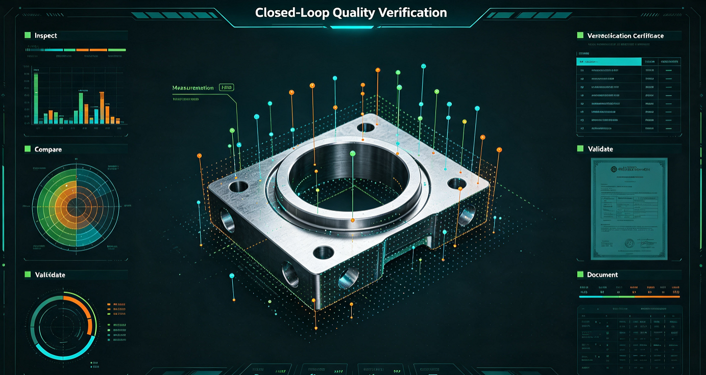
We provide multiple levels of inspection documentation depending on your requirements:
- CMM point measurement or scanning against your datum scheme (not against a convenient shop reference) — this is our baseline for all complex 5-axis work.
- First Article Inspection (FAI) report on request — standard practice for new part numbers; verifies every drawing characteristic before batch release.
- Full dimensional report against a ballooned drawing — available for any part where you need complete traceability.
- Material and surface-treatment certificates including mill test reports (MTRs), heat treatment records, and coating/plating certifications where applicable.
- Custom measurement-point programs — supply your balloon drawing or point list and we will measure to your specification.
What We Measure and How
Different feature types require different measurement methods. The table below maps each feature category to the method we use, the typical output format, and when each is applied.
| Feature Type | Measurement Method | Typical Output | When Applied |
|---|---|---|---|
| Complex surface profile (impeller blades, contoured housings, mould cavities) | CMM point measurement or scanning vs CAD nominal surface | Deviation report (point-by-point or colour-map); max deviation; profile tolerance pass/fail | All simultaneous 5-axis contoured parts; standard for FAI |
| Blade / vane contour | CMM scanning or dense-point measurement at defined sections | Profile deviation per section; leading/trailing edge analysis; thickness map | Impeller, turbine-blade and compressor-wheel components |
| Hole position across faces | CMM with datum alignment to drawing's A-B-C reference frame | True-position report per GD&T callout; deviation from nominal position; MMC bonus if applicable | Multi-face parts with cross-face positional tolerances |
| Bore diameter and form | CMM bore circle measurement or dedicated bore gauge | Diameter; roundness; cylindricity (if specified); taper check | All precision bores; bearing journals; sealing interfaces |
| Runout / concentricity | CMM radial deviation scan or indicator setup on rotary axis | Total indicated runout (TIR); concentricity value; graphical polar plot | Rotational features: shafts, hubs, flanges, bearing seats |
| Surface roughness Ra / Rz | Profilometer (contact stylus) or optical surface-measurement system | Ra value per specified area/feature; Rz if requested; traceability to instrument calibration | Where surface finish is specified on drawing (sealing faces, flow surfaces, cosmetic areas) |
| Threaded ports | Thread go/no-go gauges + CMM positional inspection of thread axis | Go/no-go result; thread-axis position relative to datum; depth verification | All threaded features where both form and position are critical |
| Thin-wall thickness | Ultrasonic thickness gauge or CMM dual-surface probing | Thickness map at defined points; min/max thickness; variation across part | Thin-wall structures (nominal wall <2 mm); lightweight aerospace-style components |
| Flatness / perpendicularity / parallelism | <CMM plane measurement with datum reference | Tolerance zone value; deviation from ideal plane/axis; graphical deviation map | Sealing faces; mounting surfaces; assembly interfaces |
Documentation Package: What You Can Request
Standard Documentation (Included)
- Dimensional inspection report with key characteristics measured
- CMM output referenced to customer datum scheme (A-B-C sequence as drawn)
- Material certificate (mill test report) confirming alloy grade and heat number
- Surface-treatment certificate where applicable (anodizing, plating, passivation record)
- Final outgoing quality confirmation before shipment
Premium Documentation (Available on Request)
- First Article Inspection (FAI) report — full AS9102-style or equivalent ballooned-drawing verification of every characteristic
- Full dimensional report against customer-supplied balloon drawing with all dimensions reported
- CMM scanning data (point cloud or colour-map deviation file) for contoured surfaces
- Customer-specified measurement points — supply your point list or balloon drawing and we measure to it
- 100% critical-dimension inspection — defined sampling plan or 100% check on flagged features (quoted separately)
- SPC trend data for production runs (Cpk analysis on key characteristics over batch)
Why Datum Alignment Matters More Than Instrument Accuracy
The most common cause of inspection disagreement between supplier and customer is not CMM accuracy — it is datum establishment methodology. Both parties may have perfectly calibrated CMM machines that produce different results because they are measuring from different reference frames.
The Problem Scenario
Your drawing defines datum A as a bore axis, datum B as a perpendicular face, and datum C as a slot. The supplier's CMM report shows all dimensions in spec. Your incoming CMM shows three holes out of position by 0.018 mm. Both CMMs are calibrated. Who is right?
Most likely answer: both instruments measured correctly, but the supplier's CMM established datums from the largest flat face (convenient for resting the part), while your CMM followed the drawing's A-B-C bore-face-slot sequence. The results are not comparable because they are measuring different things.
How to Prevent It
- Require datum sequence in the RFQ: explicitly state that CMM output must be referenced to the drawing's A-B-C datum precedence order
- Ask for the CMM program datum setup: any reputable supplier can provide the datum-establishment sequence used for their report
- Supply a balloon drawing: numbered characteristics with datum callouts eliminate ambiguity about which reference to use for each measurement
- Watch for pattern vs scatter: if all parts shift in the same direction, it is likely a datum offset; if non-conformances are scattered randomly, it may be fixture repeatability or thermal drift
What Goldcattle Does Differently
- Our CMM reports state the datum establishment sequence used for each measurement
- Default alignment follows the drawing's GD&T datum precedence (A→B→C), not the most convenient clamping face
- If the drawing has ambiguous or missing datums, we propose a scheme and include it in the DFM feedback before cutting
- For contoured surfaces, we report deviation relative to CAD nominal in the customer's datum frame, not in an arbitrary machine coordinate system
Our Quality Certifications and Traceability System
Frequently Asked Questions
Do you provide First Article Inspection (FAI) reports?
Point measurement or scanning — which do you use by default?
Can I specify my own measurement points?
Is inspection documentation included in the quoted price?
What CMM equipment do you use?
Need Specific Inspection Documentation for Your Application?
Tell us your industry (aerospace, medical, automotive, industrial automation) and documentation standard (AS9102, PPAP, ISO 13485, or internal). We will match our inspection and reporting package to your requirement and quote it transparently.
All CMM reports include datum-sequence documentation. Calibration certificates available on request.