Custom 3D Printed Automotive Bumper Accessories
Prototype and low-volume bumper brackets, clips, sensor housings, grille inserts and air ducts — printed straight from your CAD file, with no tooling and no minimum order. Send a STEP or STL file and get a physical part you can hold against the bumper in 3–5 business days.
Illustration of typical accessory locations. Send your own CAD — we print to your geometry, not to a catalogue.
What You Need to Know Before You Request a Quote
Six parameters that decide whether a bumper accessory is a good fit for additive manufacturing — and what we need from you to price it.
If a capability is not listed here, we will not claim it. Every parameter above reflects equipment and processes we run. Anything outside that scope — metal printed parts, structural crash components, certified safety parts — we will tell you up front and point you to the right process.
What Are Custom 3D Printed Bumper Accessories?
They are the plastic components that mount on, into or behind a vehicle bumper — brackets, clips, sensor housings, covers, inserts, ducts and trim — produced additively from a CAD file instead of from an injection mould.
For a procurement or engineering team, the useful definition is not about the material. It is about when printing beats tooling: the geometry is still changing, the annual volume is too low to amortise a mould, or the programme schedule cannot absorb a 15–30 day tooling lead time. In those three situations, a printed part is usually the fastest and cheapest route to a physical component you can test.
Bumper Accessories We Print
Scope boundary — read this before you send an RFQ. We supply prototype, styling and low-volume functional accessories. We do not supply crash-relevant structural bumper beams, energy absorbers, or pedestrian-impact certified components. Those remain moulded or formed parts validated by the vehicle manufacturer, and we will say so rather than quote for them.
Where Printed Bumper Accessories Are Actually Used
Five buying situations. Each one has a different reason for choosing printing over tooling — and a different set of requirements.
Prototype Development
Fit-check parts printed in days so the bumper assembly can be validated on a physical vehicle before any tooling commitment. Geometry changes cost nothing but a new file.
Typical driver: schedule riskAftermarket & Styling
Grille inserts, bezels, sensor surrounds and trim pieces produced in volumes too low to justify a mould, or for model variants that will never reach tooling volume.
Typical driver: low annual volumeMotorsport & Track
Brake ducts, camera mounts and quick-turn brackets revised between events. Design iteration is the point — printing makes each revision cost the same.
Typical driver: rapid iterationVehicle Restoration
One-off or small-run replacement clips, covers and brackets for models where the original tooling no longer exists and no spares are available.
Typical driver: obsolete partEV & Low-Volume Platforms
Sensor and camera mounts for platforms still in definition, where bracket geometry tracks with sensor selection and will not freeze for months.
Typical driver: unfrozen geometryIs 3D Printing Right for Your Bumper Accessory?
This is the question behind most enquiries we receive. The honest answer depends on quantity, geometry stability and what the part has to survive.
Choose 3D Printing
Fastest and cheapest path to a real part- You need 1–100 pieces
- Geometry is still changing between revisions
- You want to avoid tooling cost entirely
- You need a fit-check or form-study part this week
- You must validate fit before committing to a mould
- The part has internal channels or complex ducting
Consider CNC Machining
When accuracy or material wins over speed- Tolerances tighter than printing can hold
- The part has to be metal
- High-strength functional load paths
- Machined surface finish required as-supplied
- Critical sealing or bearing faces
- See CNC machining capabilities
Consider Injection Molding
When volume pays back the tooling- High annual volume with a stable forecast
- Unit cost at scale is the deciding metric
- Geometry is frozen and validated
- Production-grade resin and surface required
- Repeatability across tens of thousands of parts
- See injection molding capabilities
The usual sequence is not either/or. Most programmes print the bracket, freeze the geometry after fit validation, and then tool it. Because we run printing, CNC machining and injection molding under one roof, that handover does not mean finding a new supplier.
Material Selection for Bumper Accessories
Material choice is not about picking the strongest option. It is about matching the part to where it sits, what it survives, and how it needs to look.
| Material | Why It Gets Chosen | Typical Bumper Use | Watch Out For |
|---|---|---|---|
| ABS | Good stiffness-to-impact balance. Sands, paints, bonds and vapour-smooths easily. The general-purpose default. | Brackets, housings, trim, painted prototypes | Poor long-term UV resistance — not the first choice for parts living in direct sunlight |
| ASA | ABS-like processability with substantially better UV and weather resistance, so colour and finish hold up outdoors. | Exterior grille inserts, sensor covers, bezels | Higher material cost than ABS |
| PA12 (Nylon) | High toughness, wear and fatigue resistance. SLS and MJF parts are close to isotropic, so strength is not orientation-dependent. | Clips, snap-fits, functional brackets, ducts | Grainy as-printed surface — needs blasting or coating for visible parts |
| TPU | Elastomer with selectable Shore hardness. Absorbs vibration and seals against the bumper face. | Grommets, flexible boots, isolator pads, soft-touch trim | Flexible walls behave differently from rigid ones — geometry needs review before printing |
| PC | High heat resistance and stiffness where a part sits near lamps, radiators or brake heat. | Lamp-adjacent housings, under-bonnet ducts | Higher print cost; processing needs tighter control |
| PLA | Dimensional stability and low cost for parts that only need to look right and be measured. | Appearance mock-ups, display parts, form checks | Not suitable for functional or heat-exposed parts |
How to choose — three questions. Where does the part sit (interior, exterior UV, under-bonnet heat)? What does it have to survive (clip flex cycles, stone impact, car-wash chemicals)? What finish does it need (as-printed, painted, textured)?
If you are unsure, send the application description with your RFQ. We will come back with two recommended materials and the trade-off between them written out, rather than a single number on a quote line.
A wider list — including PETG, PP, PA12 GF/GB, PEEK, PEKK and ULTEM — is covered on our 3D printing services page.
Which Printing Technology Fits Your Part
Four processes, and the differences that actually matter when the part has to clip into a bumper and stay there.
| Criteria | FDM | SLA | SLS | MJF |
|---|---|---|---|---|
| Process | Extruded thermoplastic filament | Laser-cured liquid resin | Laser-sintered PA12 powder | Multi-jet fused PA12 powder |
| Typical Accuracy | ±0.2 mm | ±0.1 mm | ±0.15 mm | ±0.2 mm |
| Surface As-Printed | Visible layer lines, Ra 8–20 μm | Smooth, Ra 1–3 μm | Grainy, Ra 5–10 μm | Grainy, Ra 5–8 μm |
| Min Wall Thickness | 1.0 mm | 0.5 mm | 0.8 mm | 1.0 mm |
| Support Required | Depends on geometry | Yes | No — powder supports the part | No — powder supports the part |
| Strength Character | Good, but anisotropic — weakest between layers | Moderate, more brittle | Good, near-isotropic | Excellent, near-isotropic |
| Max Build Envelope | 1000 × 1000 × 1000 mm | 800 × 800 × 550 mm | 350 × 350 × 420 mm | 380 × 284 × 380 mm |
| Best For Bumper Work | Large ducts, prototype bumper sections, jigs | Grille inserts, bezels, smooth masters for painting | Functional clips, brackets, snap-fits | Repeatable low-volume production runs |
These are typical achievable figures for each technology — not a blanket guarantee on every feature. A flat, well-oriented bracket prints more predictably than a long, thin, curved duct. Final tolerance is confirmed per part after DFM review, and we will flag which dimensions are achievable as-printed versus which need a secondary operation.
Design Considerations Before You Send the File
Four checks that prevent most failed bumper accessory prints. These are the rules we apply during DFM review — knowing them up front saves a round trip.
Wall Thickness
Too thin and the feature will not survive depowdering or support removal; too thick and you pay for material and build time you do not need.
Minimum as-printed: 0.5 mm SLA · 0.8 mm SLS · 1.0 mm FDM & MJF. For a clip or bracket that takes assembly load, start at 1.5–2.0 mm.Snap-Fits & Clips
Snap-fits are the most commonly under-designed bumper feature. Failure is usually at the hinge root, and it is usually an orientation problem rather than a material problem.
Orient so the layer plane runs along the flex direction. Default to PA12 (SLS/MJF) for repeated flex. Radius the hinge root — no sharp internal corners.Mounting Holes
Small holes close up during printing and finishing. Printed holes are also rarely round enough for a press-fit bush straight off the machine.
Minimum diameter: 0.5 mm SLA · 1.0 mm SLS & MJF · 2.0 mm FDM. Where fit is critical, print slightly undersize and ream or drill to final size.Warpage & Flatness
Large flat surfaces are the primary warpage risk, particularly in ABS and PC. A bracket that bows 1 mm will not sit flush against the bumper face.
Break up large flat faces with ribs or steps; avoid long unsupported spans; expect flatness to be specified on the drawing where it matters.These are starting rules, not a substitute for printability review. Every order includes a free DFM check covering printability analysis, material recommendation and build orientation — before anything goes on a machine. If we see a feature that will not survive, you hear about it at that stage, not at delivery.
Customization Capability & CAD Requirements
Every part we print is made to your geometry. There is no catalogue — the file you send is the part you get.
Send CAD + Requirements
STEP, STP, STL, IGES, OBJ or 3MF. Native SolidWorks and CATIA files accepted. A 2D PDF or DWG can be added as reference, but not as the sole input.
Engineering Review
We read the geometry, check wall thickness, snap-fit design, hole sizes and orientation risk against the process you selected.
DFM Check & Quote
You get the printability feedback, material recommendation and a quote with process, quantity, finish and lead time stated separately.
Printing
Parts are nested into the build for best orientation and material efficiency. Standard lead time is 3–5 business days; rush and expedited options on request.
Post-Processing
Support removal, depowdering, sanding, blasting, priming, painting or dyeing — each as a defined step on the order, not a default.
QC Inspection & Delivery
Dimensional and visual inspection against the drawing, packed per part number, shipped on the carrier you nominate.
What to include in your RFQ: 3D file, quantity, material preference (or the application and we will advise), finish required, which dimensions are critical, and the delivery date you are working to. That is enough for a priced quote in most cases.
Dimensional Accuracy & Quality Control
Dimensional accuracy for a printed bumper accessory depends on four things working together: the technology (±0.1 mm SLA, ±0.15 mm SLS, ±0.2 mm FDM and MJF are typical achievable figures), the material, the geometry, and the build orientation.
We do not quote a single tolerance that applies to every feature on every part. We review your drawing, tell you which dimensions are achievable as-printed, and tell you where a reamed hole or a secondary CNC operation is the honest answer. That conversation happens before quotation, not after delivery.
What We Check
- Incoming material verification — material lot and build parameters recorded against the job
- First article inspection (FAI) — first part from a new build measured against the drawing
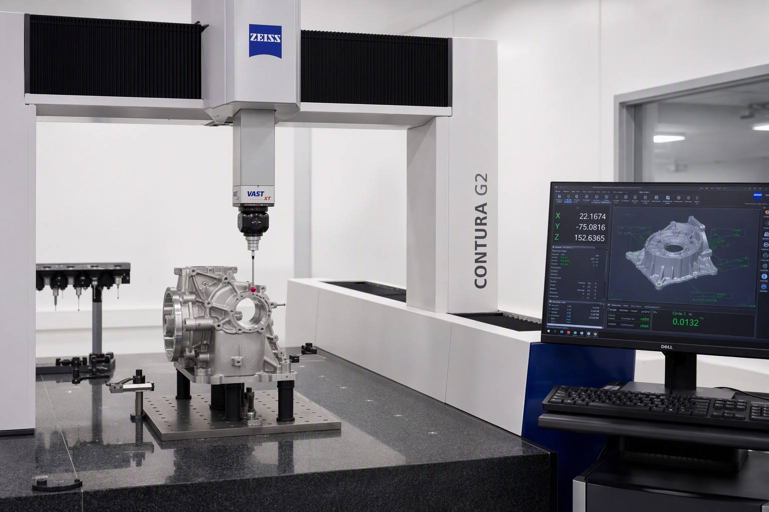
- Dimensional inspection — callipers and gauges against drawing callouts; CMM where a feature requires it
- Visual inspection — layer consistency, support marks, surface defects, colour consistency
- Functional fit check — test assembly onto the mating part or fixture when you supply it
- Final inspection before packing — quantity, finish, labelling, packaging condition
Inspection scope is agreed with you at quotation. We will not state "100% inspected" on a part unless that is what the order actually specifies and the inspection plan supports it. If you need FAI documentation, a defined AQL, or measurement reports on specific features, ask for it in the RFQ and it will be quoted as a line item.
Finishing Options for Printed Bumper Parts
Finishing is where a printed part stops looking printed. Each option below is a service we actually run — not a list of everything theoretically possible.
Sanding
Manual and machine sanding through progressive grits to remove layer lines and prepare for coating.
Bead Blasting
Uniform matte texture that removes print grain — the standard first step for SLS and MJF nylon parts.
Vapour Smoothing
Chemical smoothing that closes surface porosity and gives a near-injection-moulded gloss on compatible materials.
Priming
Spray primer applied as a defined layer so the topcoat adheres and the surface reads consistently across parts.
Painting & Custom Colour
Single or two-stage coating to a colour code you specify, with gloss level called out on the order.
Polishing
Progressive polishing for gloss or semi-gloss finishes on resin and select thermoplastic parts.
Texturing
Applied or printed texture to match adjacent moulded trim so the part does not read as an add-on.
Dyeing
Colour infusion for SLS and MJF nylon — colour goes into the part rather than sitting on top of it.
Also available: CNC secondary machining for holes and sealing faces that need a tolerance printing cannot hold, and light assembly — heat-set inserts, bushings, adhesive bonding — so the part arrives ready to fit.
Specify the finish on the drawing. "As-printed", "sanded and primed", and "painted to [code]" are three different quotes, and we price them separately rather than bundling a default.
From Printed Fit Check to Frozen Geometry
A representative project profile for a bumper sensor bracket and grille insert set.
- Parts
- Sensor mounting bracket, grille insert
- Material
- PA12 (SLS) for brackets · SLA resin for grille insert masters
- Process
- SLS + SLA · bead blasting · priming
- Quantity
- Prototype set, followed by a low-volume batch
- Application
- Front bumper assembly, exterior visible
Requirement
The bracket had to locate the parking sensor correctly against the bumper face and survive repeated clip-in cycles during assembly trials without cracking. The grille insert was exterior-visible and needed a surface that could be primed and painted to match the surrounding trim.
What We Did
Brackets were printed in PA12 by SLS so the snap features were near-isotropic and would not fail along a layer plane. Grille inserts were produced in SLA for surface quality, then primed to give the paint shop a consistent substrate. Build orientation was set to keep snap-fit flex across the layer direction.
Result
Fit was verified against the customer-supplied bumper before any tooling was committed. One clip feature was revised after the first assembly trial, and the updated file was printed and shipped without a tooling modification cost. The low-volume batch was delivered blasted, primed and labelled per part number. Geometry was frozen after validation, and the programme moved to injection molding at that point.
On numbers: the profile above describes the shape of this type of project, not a specific customer's data. We do not publish customer names or programme-specific figures. Your quantities, tolerances, lead times and inspection scope are confirmed in writing with your quotation and first-article report.
3D Printing vs CNC Machining vs Injection Molding
The three processes we run in-house, compared on the factors that decide a bumper accessory order.
| Factor | 3D Printing | CNC Machining | Injection Molding |
|---|---|---|---|
| Tooling | None | CAM programming and fixturing | Production mould required |
| Best Quantity | 1 – 1,000 pcs | 1 – 500 pcs | 5,000+ pcs |
| Typical Tolerance | ±0.1–0.2 mm | ±0.01 mm typical; ±0.005 mm on qualified features | ±0.05 mm typical; ±0.02 mm on tight features |
| Lead Time to First Part | 3–5 business days | Days, including setup and fixturing | 15–30 days including tooling |
| Design Change Cost | None — send a new file | Low — reprogram | High — mould modification |
| Material Range | Engineering thermoplastics and elastomers | Any machinable metal or plastic | Any injection-grade resin |
| Unit Cost Behaviour | Flat — the 500th part costs about the same as the first | Falls slowly with volume | Falls steeply once tooling is amortised |
| Best For | Prototypes, unfrozen geometry, low volume | Tight tolerance, metal, structural parts | Stable high-volume production |
The crossover quantity between printing and molding depends on part size, material and finish — it is not a fixed number. If your forecast sits near the boundary, send us both volumes and we will price both routes so you can see the crossover rather than guess at it.
Why Buyers Use Goldcattle for Bumper Accessories
Founded in 1998 · 100+ machines across our six core processes.
One-Stop Manufacturing
3D printing sits alongside CNC machining, injection molding, mold making, die casting and sheet metal fabrication in one facility under one ISO 9001:2015 quality system. All six core processes are performed in-house.
Prototype to Production
When the geometry freezes, the same team that printed your prototype can tool and mould it. No re-sourcing, no re-qualifying a new supplier at the point where the risk is highest.
Low MOQ
One piece minimum on printed parts. Obsolete clips, one-off restoration parts and single fit-check brackets are all viable orders — there is no volume gate to get past.
Engineering Support
Free DFM review on every order: printability analysis, material recommendation, build orientation. You get the trade-off in writing before you commit to a process.
We supply automotive parts across prototype, aftermarket, motorsport and restoration programmes. If you need a capability outside the six processes we run in-house, we will say so rather than quote for something we cannot deliver.
How to Place an Order
Send Your File
CAD plus quantity, material, finish and target date.
DFM Review
Printability, wall thickness, orientation, material advice.
Quote
Process, quantity, finish and lead time quoted as separate lines.
Confirmation
Order confirmed with inspection scope and packaging agreed.
Print & Finish
Parts nested, printed, post-processed to the specified finish.
Inspect & Ship
QC against the drawing, packed per part number, shipped worldwide.
Technical Specifications
The full parameter set for custom 3D printed bumper accessories — process, accuracy, materials, design limits, finishing and ordering. Figures reflect our in-house equipment; anything outside this table is flagged before quotation rather than assumed.
| Parameter | Specification |
|---|---|
| 1 · Product Identification | |
| Product Name | Custom 3D Printed Automotive Bumper Accessories |
| Product Category | Prototype and low-volume plastic automotive accessories |
| Typical Parts | Mounting brackets Retainer clips Parking sensor housings Tow hook covers Grille inserts Air ducts and brake cooling ducts Trim and bezel pieces Spacers and bushings Camera and radar mounts Prototype bumper sections |
| Manufacturer | Xiamen Goldcattle Plastic & Metal Products Co., Ltd. |
| Place of Origin | Xiamen, Fujian, China |
| Founded | 1998 |
| 2 · Manufacturing Process | |
| Processes | FDM SLA SLS MJF |
| Tooling | Not required — no mould, no fixture |
| Layer Height | SLA 25–100 μm SLS 100–120 μm FDM 100–300 μm MJF 80 μm |
| Support Structure | SLA: required SLS: not required FDM: depends on geometry MJF: not required |
| Build Orientation | Optimised per part during DFM review |
| Secondary Operations | CNC machining Drilling and reaming Heat-set inserts Adhesive bonding Light assembly |
| 3 · Dimensional Accuracy | |
| SLA | ±0.1 mm |
| SLS | ±0.15 mm |
| FDM | ±0.2 mm |
| MJF | ±0.2 mm |
| Basis | Technology-level typical achievable values, not a blanket guarantee on every feature Final tolerance confirmed per drawing after DFM review Critical features may require reaming or CNC secondary machining |
| 4 · Build Envelope (Max) | |
| FDM | 1000 × 1000 × 1000 mm |
| SLA | 800 × 800 × 550 mm |
| SLS | 350 × 350 × 420 mm |
| MJF | 380 × 284 × 380 mm |
| Oversize Parts | Larger parts can be printed in sections and bonded Introduces a joint line and a dimensional step — discuss before designing for it |
| 5 · Surface Quality (As-Printed) | |
| SLA | Ra 1–3 μm — smooth |
| SLS | Ra 5–10 μm — grainy |
| MJF | Ra 5–8 μm — grainy |
| FDM | Ra 8–20 μm — visible layer lines |
| After Finishing | Sanding, blasting, priming and painting to a specified Ra or appearance standard |
| 6 · Materials | |
| Standard Grades | ABS ASA PA12 (Nylon) TPU PC PLA |
| Extended Grades | PETG PP PA11 PA12 GF PA12 GB PEEK PEKK ULTEM SLA resins (standard / tough / high-temp) |
| Exterior / UV Exposure | ASA recommended over ABS |
| Flexible / Snap-Fit Features | PA12 by SLS or MJF recommended |
| Heat-Adjacent Locations | PC |
| Visual or Mock-Up Only | PLA — not for functional or heat-exposed parts |
| Selection Basis | Confirmed per application: mounting location, service load, required finish |
| 7 · Design Limits (DFM) | |
| Min Wall Thickness | SLA 0.5 mm SLS 0.8 mm FDM 1.0 mm MJF 1.0 mm |
| Recommended Wall Thickness (Load-Bearing) | 1.5–2.0 mm |
| Min Hole Diameter | SLA 0.5 mm SLS 1.0 mm MJF 1.0 mm FDM 2.0 mm |
| Max Overhang | SLA 45° (with support) SLS unlimited MJF unlimited FDM 45° |
| Snap-Fit Guidance | Orient the build so the layer plane runs along the flex direction Radius the hinge root No sharp internal corners |
| Warpage Control | Break up large flat faces with ribs or steps Avoid long unsupported spans Specify flatness on the drawing where it matters |
| DFM Review | Free with every order — printability, material recommendation, build orientation |
| 8 · Surface Finishing | |
| Available Processes | Sanding Bead blasting Vapour smoothing Priming Painting and custom colour Polishing Texturing Dyeing |
| Colour Matching | To a colour code specified on the drawing, with gloss level called out |
| Quoting | Printing and finishing are quoted as separate line items |
| 9 · Quality Control | |
| Inspection Stages | Incoming material verification First article inspection (FAI) Dimensional inspection Visual inspection Functional fit check (when the mating part or fixture is supplied) Final inspection before packing |
| Measuring Equipment | Calipers and gauges as standard CMM where the feature requires it |
| Inspection Scope | Agreed at quotation Additional documentation (FAI report, defined AQL, feature measurement reports) quoted as a separate line item '100% inspected' is stated only when the order actually specifies it |
| Quality System | ISO 9001:2015 |
| 10 · Order and Delivery | |
| MOQ | 1 piece |
| Economic Quantity Range | 1 – 1,000 pcs Above this, compare against injection molding |
| Standard Lead Time | 3–5 business days |
| Rush Lead Time | 1–2 business days |
| Expedited Lead Time | 24 hours |
| Accepted 3D Files | STEP STP STL IGES OBJ 3MF Native SolidWorks and CATIA accepted |
| Reference Files | 2D PDF or DWG accepted as reference only — not as sole input |
| RFQ Checklist | 3D file Quantity Material preference (or the application) Finish required Critical dimensions Target delivery date |
| Packing | Labelled per part number |
| Shipping | Worldwide, on the carrier nominated by the customer |
| IP Protection | NDA available before file transfer |
| 11 · Scope Boundary | |
| Supplied | Prototype, styling and low-volume functional bumper accessories |
| Not Supplied | Crash-relevant structural bumper beams Energy absorbers Pedestrian-impact certified components |
| Note | All parameters above reflect in-house equipment and processes Capabilities outside this scope are stated up front rather than quoted |
Accuracy figures are typical achievable values for each technology, not a guarantee on every feature. Final tolerance, inspection scope and lead time are confirmed in writing with your quotation. Need a parameter that is not listed? Send the requirement and we will confirm whether we can hold it.
Questions Buyers Ask Before Ordering
What file formats do you accept?
STEP, STP, STL, IGES, OBJ and 3MF. Native SolidWorks and CATIA files are also accepted. A 2D PDF or DWG is useful as reference for tolerances and finish notes, but we need a 3D file to produce a printed part.
What is the minimum order quantity?
One piece. There is no tooling to amortise, so a single bracket or a one-off obsolete clip is a perfectly viable order. That said, unit cost does fall somewhat as we can nest more parts into one build — we will show you the difference if your quantity is flexible.
Can 3D printed bumper accessories be used as end-use production parts?
Yes, in the right application — and this is where scope matters. Printed parts work well as functional accessories: brackets, mounts, ducts, clips, covers and trim that are not carrying structural crash load. They are not a substitute for a crash-relevant bumper beam, an energy absorber, or any component requiring pedestrian-impact or homologation certification. If your part sits near that boundary, send us the application and we will give you a direct answer.
What tolerances can you hold on a printed bumper bracket?
Typical achievable accuracy is ±0.1 mm for SLA, ±0.15 mm for SLS, and ±0.2 mm for FDM and MJF. That is a technology-level figure, not a promise on every feature — final capability depends on material, geometry and build orientation. We review your drawing before quoting and tell you which dimensions are achievable as-printed and which need reaming or a secondary CNC operation.
Which material is best for an exterior bumper accessory?
For parts that live in direct sunlight, ASA is usually the better choice over ABS because it holds colour and finish far better under UV. For parts that must flex — clips and snap-fits — PA12 nylon printed by SLS or MJF is the default. If the part sits near heat sources, PC is worth considering. Send the application and we will recommend two options with the trade-off written out.
Will a printed clip be strong enough for repeated assembly?
It can be, if the design and orientation are right. Most printed snap-fit failures are orientation failures, not material failures — the part splits along a layer plane. We print flexing features in PA12 by SLS or MJF, which is close to isotropic, and orient the build so flex runs across the layer direction. Radius the hinge root and avoid sharp internal corners.
Can you paint printed bumper parts to match a colour code?
Yes. We sand or bead blast, apply primer, then topcoat to the colour code you specify with the gloss level called out. For exterior parts, ASA or a primed SLA substrate gives the most consistent result. Specify the colour reference and gloss on the drawing so it can be quoted as a defined step.
How large can a printed bumper part be?
Maximum build envelope depends on technology: 1000 × 1000 × 1000 mm for FDM, 800 × 800 × 550 mm for SLA, 350 × 350 × 420 mm for SLS and 380 × 284 × 380 mm for MJF. Larger parts can often be printed in sections and bonded, but that introduces a joint line and a dimensional step — worth discussing before you design for it.
How long does a prototype bumper accessory take?
Standard lead time is 3–5 business days from confirmed order, with rush (1–2 days) and expedited (24 hours) options available depending on technology, size and finish. Finishing steps such as priming and painting add time — we quote printing and finishing separately so you can see what each costs in both money and days.
Can you print a full bumper?
A full bumper cover can be printed in sections on our FDM platform for form, fit and show purposes. It is not a roadgoing replacement part — printed sectioned covers do not have the impact performance or the surface consistency of a moulded bumper. If you need a full cover, we would normally print sections for validation and then quote tooling for the production part.
Do you sign NDAs, and how is my design protected?
Yes, we sign NDAs before file transfer if your programme requires it. Files are used only for the quoted work and are not shared outside the engineering team handling your project. We do not publish customer names, part drawings or programme details without written permission — which is also why our case studies describe project types rather than named customers.
What should I include in my RFQ to get an accurate quote?
Six things: the 3D file, the quantity, the material preference (or the application and we will advise), the finish required, which dimensions are critical, and your target delivery date. If you have a mating bumper or fixture you want the part test-fitted to, mention that too — it changes what we can verify before shipping.
Ready to Prototype Your Custom Bumper Accessory?
Send the file and the application. You will get a printability review, a material recommendation and a quote with process, quantity, finish and lead time stated separately — no bundled assumptions.