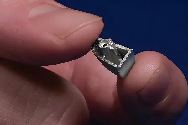
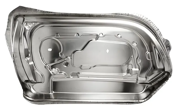
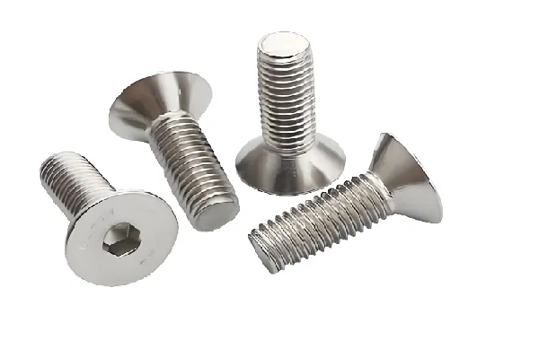
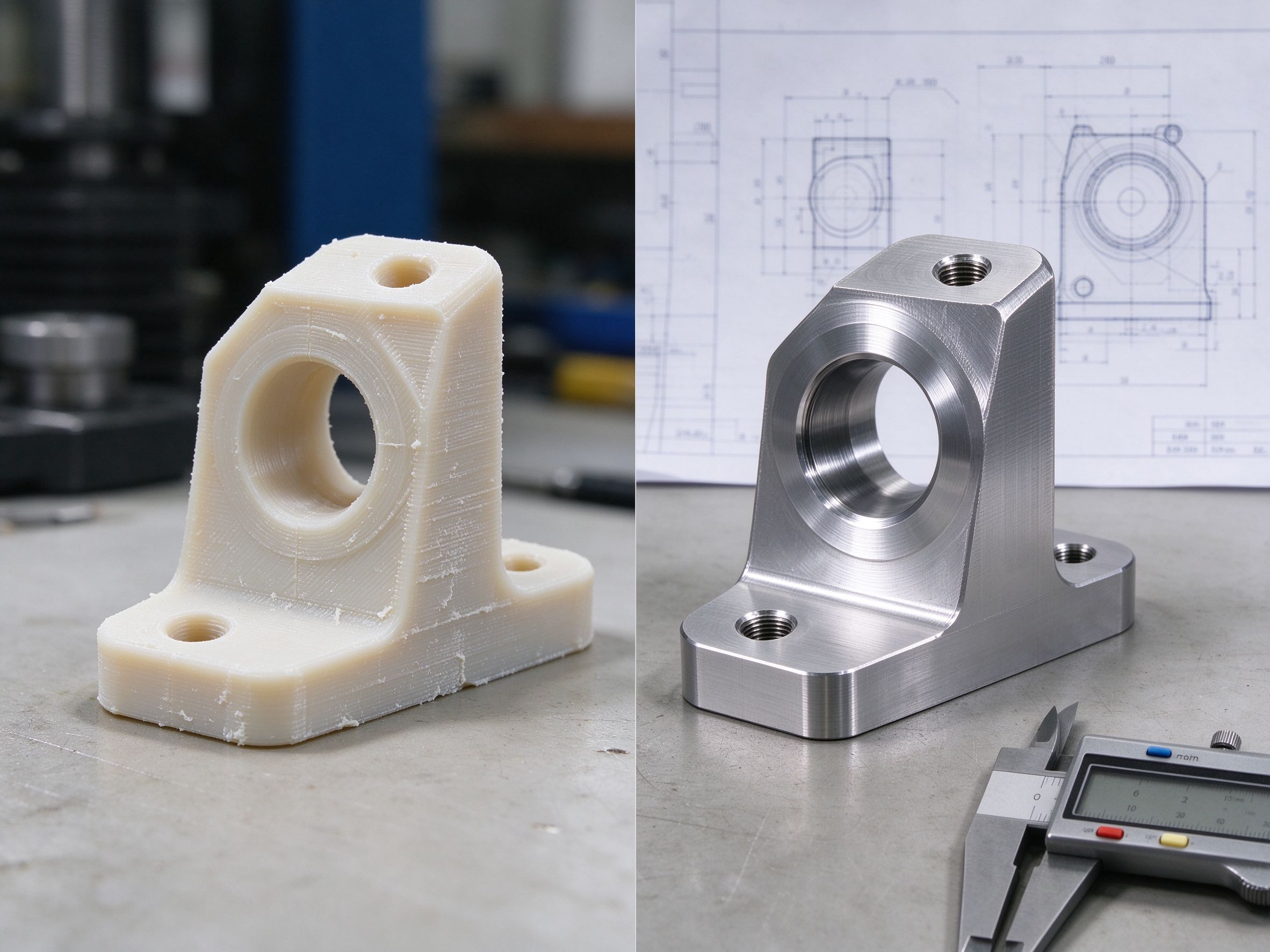
3D printing creates geometry that benefits from additive freedom; CNC machining produces the features that need controlled datums, holes, threads and finished surfaces. This page explains when to combine them, how to allocate features between processes, and how one supplier manages the whole workflow.
At a Glance
Hybrid manufacturing combines additive manufacturing (3D printing) and subtractive manufacturing (CNC machining) in one coordinated workflow. 3D printing is used where geometric freedom, part consolidation or rapid iteration helps; CNC machining is used where controlled datums, tight interfaces, holes, threads, sealing surfaces or surface finish are required. Hybrid does not automatically mean one machine — it can be a coordinated process across separate 3D printing and CNC equipment.
Hybrid Workflow vs Integrated Hybrid Machine
Two different things are called "hybrid" in industry. They are not the same, and the distinction matters when you evaluate a supplier:
| Concept | Meaning | Relevance to this page |
|---|---|---|
| Hybrid manufacturing workflow | 3D printing + CNC machining coordinated across one or more machines | The main model we describe |
| Integrated hybrid machine | Additive and subtractive operations in the same machine/work envelope | A specialized machine class, not required for hybrid workflow |
| Hybrid part finishing | Printed near-net shape, then CNC on critical features | The most common hybrid route |
| Hybrid product development | 3D printed prototype → CNC functional prototype → production | A program-level hybrid workflow |
Which Process Does What?
Hybrid manufacturing is feature allocation, not process stacking. Each feature goes to the process that manufactures it most effectively:
| Part requirement | 3D printing | CNC machining |
|---|---|---|
| Complex internal channels | Primary | Limited access |
| Lattice / lightweight structures | Primary | Difficult |
| Organic or freeform geometry | Primary | Tool-access dependent |
| Rapid geometry iteration | Fast | CAM + setup time |
| Precision holes | Post-process needed | Primary |
| Threads | Post-process needed | Primary |
| Bearing fits / mating faces | Post-process needed | Primary |
| Sealing surfaces | Post-process needed | Primary |
| Datum faces for inspection | Unreliable as-printed | Primary |
| Machined surface finish | Post-process needed | Primary |
| Part consolidation | Primary | Multiple parts instead |
Four Hybrid Manufacturing Workflows
Print → CNC finish
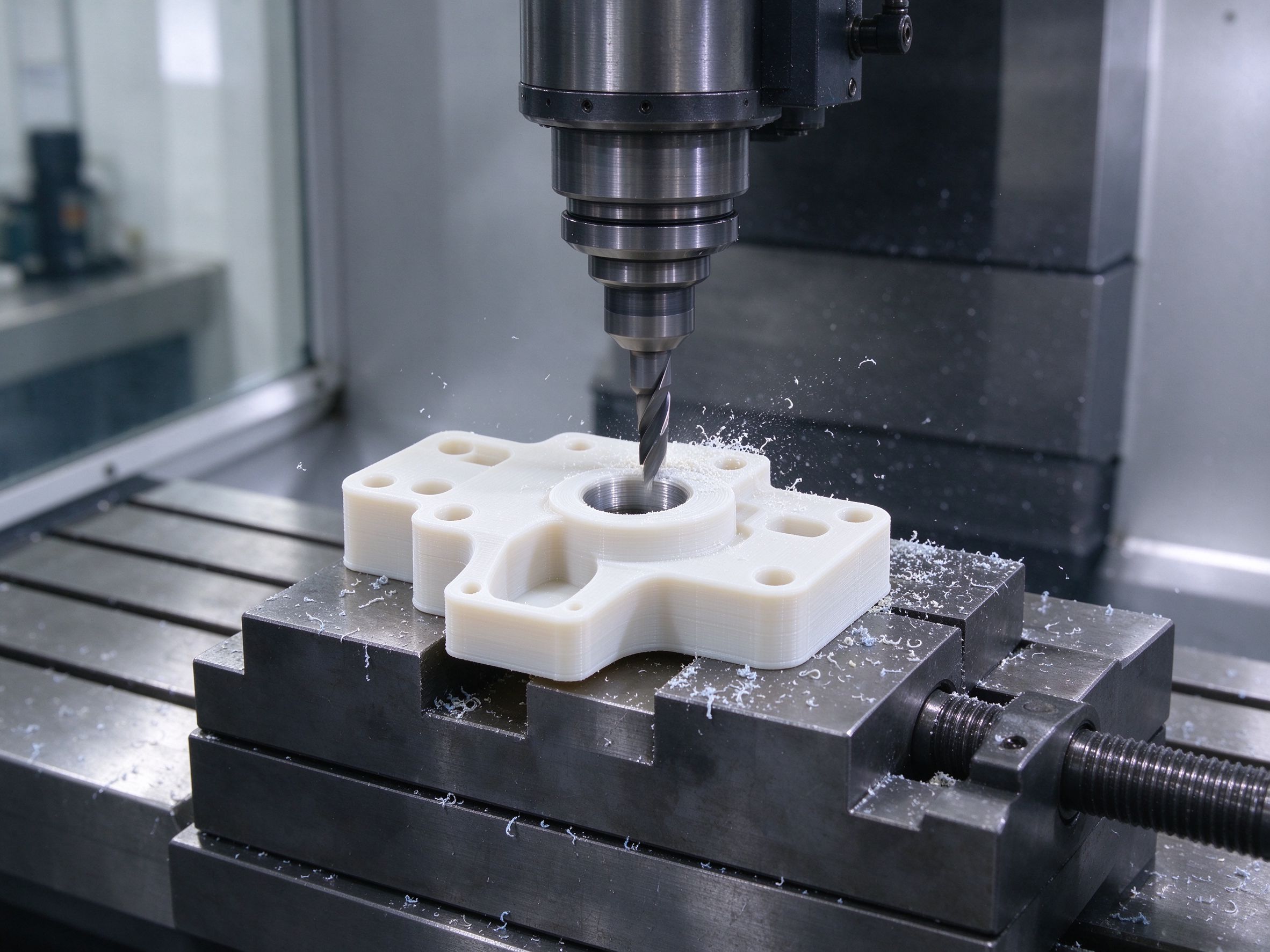
Print near-net shape, remove supports, stabilize where required, then fixture on a datum and CNC the critical features. Suits complex housings, manifolds, ducts and brackets.
Machined base + printed geometry
A CNC-machined mounting base carries a printed duct, housing or conformal feature. Feasibility depends on material and the joining method — reviewed per project.
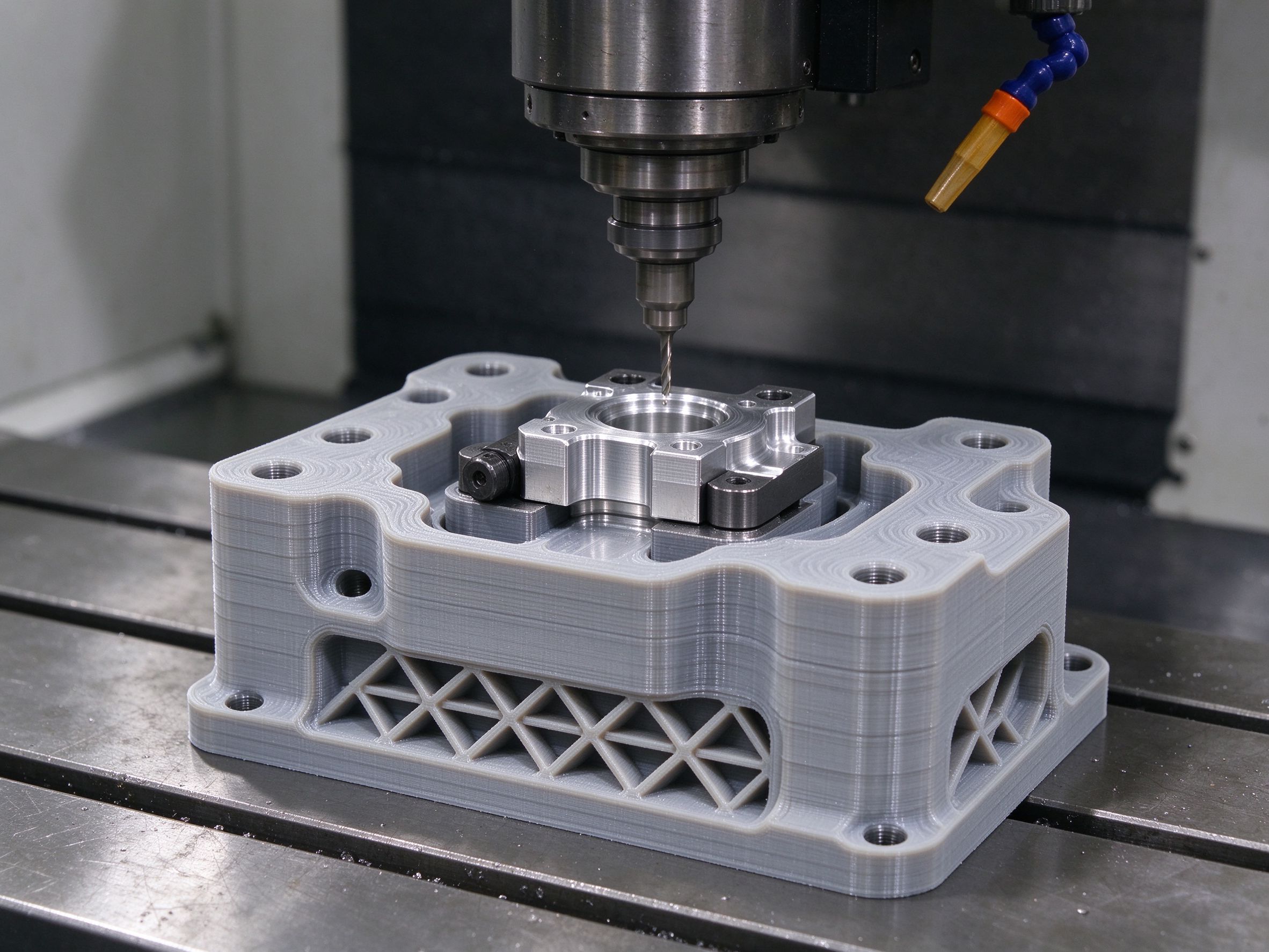
Printed fixture + CNC part
3D print the contoured fixture or nest, then CNC the production part in it. Faster fixture iteration, complex nests, lower fixture material cost.
Printed prototype → CNC functional prototype
Print to validate shape and fit while the design moves; machine when the design stabilizes and performance must be checked in production material and tolerance.
When Does Hybrid Manufacturing Make Sense?
Complex geometry + tight interfaces
The main case. Additive handles geometry; CNC handles bores, threads, faces and datums.
Internal channels + machined ports
Printed fluid or cooling channels with CNC-machined ports and sealing faces.
Part consolidation
Several components printed as one body, then mounting and interface features machined.
Topology-optimized structures
Lightweight printed structure with machined mounting datums.
Rapid functional prototypes
Print for shape and fit, machine for material, tolerance and load interfaces.
Low-volume complex end-use parts
Combining processes where dedicated tooling for high volume is not justified.
When Hybrid Manufacturing Is Overkill
Hybrid is not automatically better. The simpler process usually wins in these cases:
No complex geometry or critical interfaces beyond what one process handles.
Hybrid does not compete with injection molding at production volume.
Appearance check only, no functional machined interface.
Hybrid DFM: Design for the Finished Part
Design for hybrid means planning the printed geometry so CNC can still locate, fixture and access it afterward:
Reserve machining stock
Printed surfaces that will be machined need enough stock for clean tool engagement and final size.
Add datum features
A reference face or mounting feature that survives post-processing and carries the CNC setup.
Provide fixturing surfaces
Printed geometry must offer places to clamp or nest without crushing delicate features.
Separate cosmetic and functional surfaces
Not every surface needs machining — only the ones where machining adds value.
Plan support removal
Support contact areas must be reachable for removal before CNC setup.
Check tool reach together with build orientation
Build orientation and cutter access are planned as one decision, not two.
Datums, Workholding & Machining Allowance
After printing, a complex part has no guaranteed reference. The CNC stage needs one. Datum transfer and workholding are designed before printing, not discovered after:
Machining allowance has no universal number. It depends on printing technology, material, build orientation, expected dimensional variation, surface condition, heat treatment, stock removal and final tolerance. The allowance is defined from the final machining requirement backward, not added arbitrarily after printing.
Printed Surface vs Machined Surface
The whole part does not need to be CNC machined. A hybrid strategy is efficient when CNC is limited to the features that require tighter dimensional control or a specific surface:
| Surface | Approach |
|---|---|
| Non-functional areas | As-printed |
| Appearance / touch areas | Light post-processing where specified |
| Mounting faces, sealing surfaces, bearing seats, holes, threads | CNC machined |
| Secondary finishing | Anodizing, blasting, polishing, coating where specified |
Hybrid Quality Control
Two process stages need one common datum and one inspection logic. Quality is checked at each gate:
| Stage | What is verified |
|---|---|
| Printed part | Overall dimensions, build orientation, support/contact effects, deformation |
| Post-processing | Stress relief / stabilization where required, surface preparation |
| CNC stage | Datum setup, critical features — bores, threads, mating faces |
| Final inspection | CMM, dimensional report, surface roughness, visual, functional fit |
| Documentation | Material record, process records where required, inspection report, FAI/CoC where applicable |
Hybrid Cost Logic: Finished Part, Not Machine Stage
Compare the finished part, not the machine-hour price of a single stage:
| Route | Cost components |
|---|---|
| CNC only | Material + setup + machining + finishing + inspection |
| 3D printing only | Build + support removal + post-processing + inspection |
| Hybrid | Additive build + post-processing + fixture + CNC critical features + inspection |
Hybrid can reduce machining time, material waste or tooling commitment when the geometry justifies dividing the work between the two processes. There is no fixed break-even quantity — the economics depend on geometry, material to remove, additive cycle time, machining time, number of critical surfaces and inspection scope. Choose the lowest-risk finished-part route, not the lowest machine-stage price.
Material State Between Processes
PA12, PC, ABS, PEEK and reinforced plastics
Printed body with CNC-critical features is our standard hybrid route, aligned with our FDM, SLS, MJF and SLA capacity.
Available for selected projects
Metal 3D printing plus CNC finishing is supported on a project basis, subject to technology, material and supplier qualification. Printed metal and machined wrought stock are not treated as the same material state — porosity, residual stress, anisotropy and heat treatment are reviewed per program.
Hybrid Manufacturing by Application
| Application | Additive role | CNC role |
|---|---|---|
| Cooling manifold | Internal channels | Ports, sealing faces |
| Robotic bracket | Lightweight geometry | Mounting interfaces |
| Automotive duct | Complex routing | Mounting faces |
| Prototype housing | Fast geometry | Threads, precision holes |
| Production fixture | Complex contact geometry | Precision mounting |
| Medical component | Custom geometry | Critical interfaces |
What to Send for a Hybrid Manufacturing Review
The review decides where each process adds value — you do not need to know the final route before contacting us:
Part & design
- 3D CAD (STEP, IGES or native)
- 2D drawing with revision
- Critical dimensions, GD&T, surface finish
- Quantity (prototype / annual volume)
Material & requirements
- Preferred 3D printing material
- Critical features (holes, threads, sealing, mounting)
- Application (functional prototype, low-volume part, fixture)
- Inspection and documentation requirements
Our engineering team selects CNC, 3D printing or a hybrid route based on the part requirements — that selection is part of the service, not a question we push back to you.
Frequently Asked Questions
What is hybrid manufacturing?
Is hybrid manufacturing the same as a hybrid machine?
Can a 3D printed part be CNC machined?
Why CNC machine a 3D printed part?
Which features should be CNC machined after 3D printing?
Does a printed part need machining allowance?
Can polymer 3D printed parts be CNC machined?
Can metal 3D printed parts be CNC machined?
Is hybrid manufacturing always cheaper?
Can 3D printing be used to make CNC fixtures?
What is needed for a hybrid manufacturing quote?
Can one supplier manage both CNC and 3D printing?

Request a Hybrid Manufacturing Review
Send your CAD and drawing. We will review the geometry, decide which features should be printed and which should be machined, and return a hybrid route with fixture strategy, inspection scope and lead time.
Xiamen Goldcattle · Manufacturing since 1998 · 3D printing: SLA / SLS / FDM / MJF · CNC: 3/4/5-axis · One engineering review across both processes