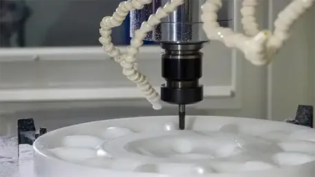
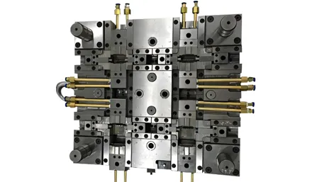
Custom injection-molded components for applications where drop impact, collision, repeated impact or sudden loading could cause cracking. Material selection and part geometry are reviewed together: a resin choice that looks strong on a data sheet can still fail at a sharp corner, a weld line or a thin section.
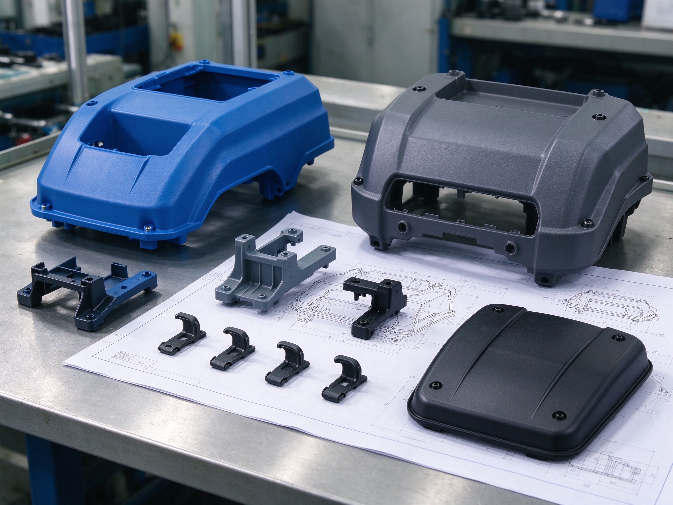
Start from how the part fails: a drop, a collision, repeated impacts, low-temperature impact or a local load at a mounting point. ABS, polycarbonate (PC) and PC/ABS blends are common candidate materials for impact-sensitive molded components; other resins may fit when the design needs flexibility, chemical resistance, wear behavior or stiffness. The choice depends on the actual resin grade, part thickness, geometry, environment and acceptance criteria. A laboratory impact value helps screening; it does not guarantee that every molded part survives a given impact.
What Impact Resistance Means for a Molded Part
Impact resistance, tensile strength, stiffness and drop performance are related but not interchangeable properties.
| Property | What it describes | Why it matters here |
|---|---|---|
| Impact toughness | Resistance to sudden loading, not slow pulling | Closest match to drops and collisions; measured on specimens under defined conditions |
| Tensile strength | Resistance to steady stretching force | A high tensile value does not prevent a brittle crack on sudden impact |
| Stiffness / modulus | How much the part deflects under load | Very stiff parts can transmit impact energy to a weak feature instead of absorbing it |
| Drop or part-level performance | Actual behavior of the finished geometry | Depends on wall shape, assembly state, temperature and contact direction, not resin data alone |
When a buyer asks whether a material "drops well," the engineering answer should combine specimen data, part geometry and any agreed sample-level testing rather than a single material number.
Why Injection-Molded Parts Crack Under Impact
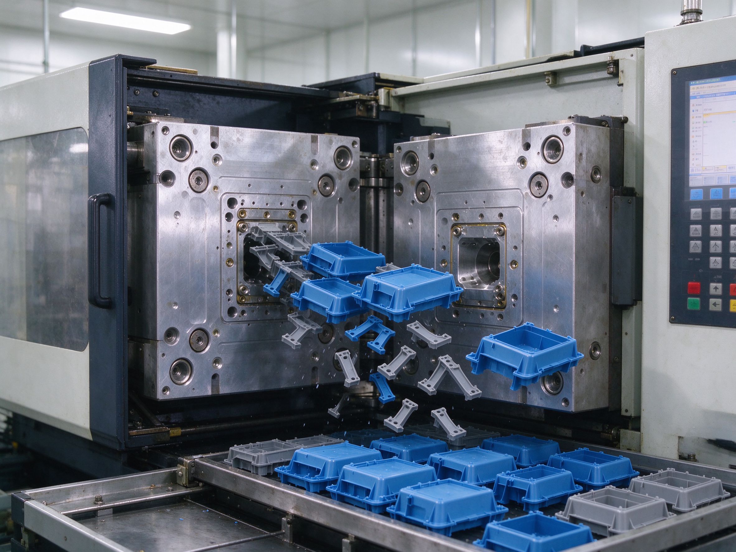
- Notches and local stress concentration. Sharp internal corners, hole edges, snap-fit roots and abrupt wall changes collect stress under impact. Replacing a more expensive resin without rounding these features usually leaves the failure point in place.
- Weld lines and flow paths. Where melt fronts meet, the local structure can be weaker; the effect depends on resin, melt temperature, pressure, venting and geometry. DFM review checks whether weld lines land near loaded or impact-prone areas.
- Wall thickness, ribs and mounting features. Thin sections, isolated thick zones, screw bosses and clips change how impact energy travels. The goal is even load distribution, not adding material everywhere.
- Molding state and service conditions. Short shots, voids, residual stress and material conditioning interact with impact temperature, moisture, chemical contact and assembly preload. A part that passes at room temperature may respond differently at low temperature or after environmental exposure.
Comparing Candidate Resins for Impact Parts
| Material direction | Considered direction | What to evaluate |
|---|---|---|
| ABS | General-purpose housings, covers, structural parts with moderate impact needs | Grade difference, service temperature, outdoor or chemical exposure, surface finish |
| Polycarbonate (PC) | Higher impact-toughness housings and structural parts where grade data supports it | Chemical environment and stress cracking risk, part thickness, appearance and post-mold handling |
| PC/ABS blend | Balance of toughness, heat behavior, processability and cost | Do not infer flame rating, heat resistance or low-temperature performance from the blend name alone; verify the grade |
| Impact-modified PA | Toughness together with selected mechanical properties | Moisture conditioning, temperature, reinforcement level and exact grade |
| PP / PE | Toughness, chemical resistance or lower-cost applications where stiffness allows | Stiffness, creep and grade-specific low-temperature impact behavior |
| TPU / TPE | Elastic deformation and energy absorption in suitable designs | Hardness, resilience, compression set and bonding behavior; not directly comparable to rigid engineering resins |
DFM Review for Impact Loads
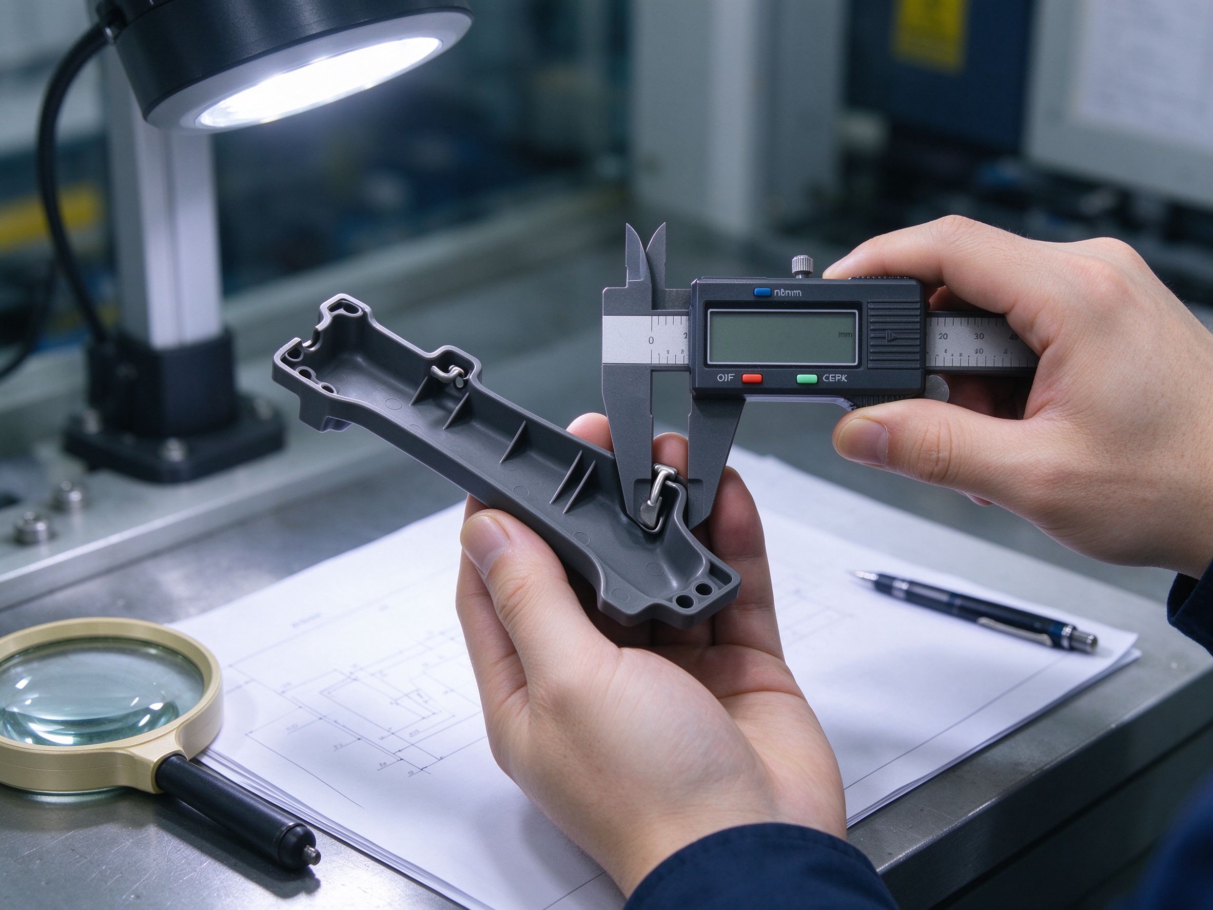
- Internal corners and sudden section changes: add radii and gradual transitions where stress concentrates.
- Screw bosses, mounting holes, clips and snap-fit roots: review undercut, root radius and assembly load.
- Rib placement and local wall thicknesses: avoid thick sections that shrink or void, and keep ribs proportioned to the main wall.
- Weld-line location: push gates and flow paths so fronts do not meet at the most loaded point when feasible.
- Gate position, runners and potential molding defects: balanced fill and controlled packing support consistent part condition.
- Environment: conditioning state, operating temperature range and chemical contact flagged alongside the drawing review.
A geometry change can improve impact behavior without moving to a costlier resin. Conversely, a resin change alone will not fix a design that concentrates impact stress at one feature.
How an Impact-Resistant Project Moves Forward
| Step | Review focus |
|---|---|
| 1. Drawing intake | Part function, installation state, expected impact scenario and operating temperature |
| 2. Material confirmation | Candidate grade screened against toughness, environment, stiffness and cost direction |
| 3. DFM review | Corners, wall transitions, ribs, bosses, gate and weld-line layout |
| 4. Tooling design | Runner, gate and cooling layout aligned with flow and weld-line targets |
| 5. Trial and sample check | Fill quality, dimensions, appearance and agreed feature inspection on first samples |
| 6. Release decision | Geometry, material state and any agreed validation evidence signed off before repeat production |
Impact Testing and Part Validation
| Level | Used for | Conditions to define |
|---|---|---|
| Material specimen impact data | Comparing resin grades at the screening stage | Standard method, specimen form, notched or unnotched, thickness, conditioning and temperature |
| Finished-part impact or drop review | Assessing how the actual shape responds | Impact energy or drop height, direction, assembly state, temperature and pass criteria |
| Production quality control | Confirming material and molding consistency between batches | Sampling rule, appearance and dimension checks, test frequency where required |
ASTM D256 covers Izod pendulum impact testing of plastic specimens. Its results depend on specimen preparation, notch condition, thickness, processing state and conditioning; specimen values are not a guarantee of finished-part performance under every environment.
Where the project requires drop testing, impact testing or external laboratory work, the method and acceptance criteria are agreed before production. In-house checks cover dimensions, appearance and agreed features; third-party testing is arranged where the equipment or qualification scope requires it.
Cost Drivers
- Resin grade family and specialty additive or toughening modification level.
- Tooling layout, cavity count, runner design and cycle-time implications.
- Wall complexity, weld-line management and added DFM features such as radii and ribs.
- Inspection level: dimension checks, appearance criteria and any material or impact records.
- Validation scope: specimen data only, or agreed part-level testing and documentation.
- Prototype quantity versus repeat-production volume and batch consistency requirements.
RFQ Checklist for Impact Parts
| Field | What to provide |
|---|---|
| Drawing and CAD | 2D drawing with dimensions; 3D model where available |
| Impact scenario | Drop, collision, repeated impact, low-temperature impact or local mounting load; include direction and frequency |
| Existing or preferred material | ABS, PC, PC/ABS, PA, PP, TPU/TPE or leave open for review |
| Operating conditions | Normal and minimum temperatures, chemical or moisture exposure, outdoor use |
| Part function and mounting | Housing, bracket, cover, clip, protective part; assembly and fastening method |
| Critical features | Key dimensions, snap features, sealing or mating interfaces |
| Validation expectation | Material data, dimensional inspection, drop test, impact test, or not yet defined |
| Volume plan | Prototype, pilot run, repeat production or expected annual volume |
| Schedule and documents | Target date and any required inspection or material records |
If the material is not yet chosen, describe the function and how the part takes impact; the engineering review identifies the key material and design questions before tooling commitment.
Frequently Asked Questions
A part cracks after a drop. Which resin should replace it?
Is PC always more impact-resistant than ABS?
Why do samples look good on data sheets but the finished part still breaks?
Should the design use glass fiber reinforcement or toughening modification?
How is impact performance proven for a molded component?
Do you guarantee that parts will not crack in service?
What details are needed for a quick material and tooling review?

Request a Quote for Impact-Resistant Molded Parts
Share the drawing, expected impact scenario, temperature range, part function and estimated quantity. The review covers resin screening, DFM risk points, mold flow considerations and the validation scope appropriate to the project.
Xiamen Goldcattle · Manufacturing since 1998 · Injection molding, tooling and related machining support