Custom Sheet Metal Chassis Fabrication for Industrial and Electronic Equipment
A chassis is a locating device before it is a box. The outline can measure perfectly and the components still will not fit, because the rails, standoffs and front panel are produced by different operations with different tolerances. This guide works from that problem outward: the mounting interface, the 19-inch standard, what welding does to a datum, and what the drawing has to carry for the assembly to close.
At a Glance
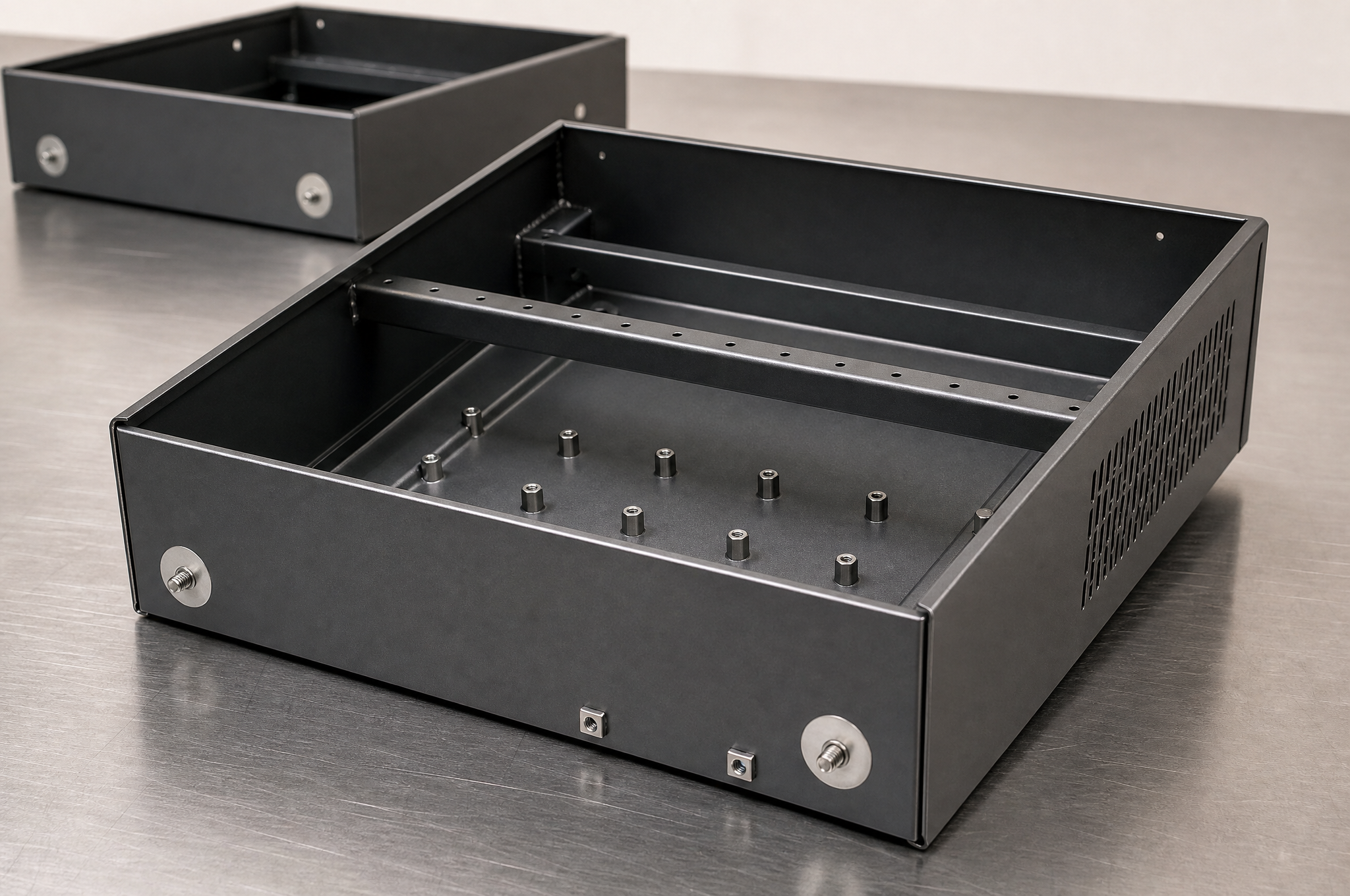
Sheet metal chassis fabrication is the manufacture of the structure that carries and locates the equipment inside a product — base, frame, side walls, rails and mounting points — built from flat sheet by cutting, forming, welding, hardware insertion and finishing. It is a different job from making an enclosure: an enclosure is dimensioned by sealing and appearance, a chassis by the position of everything mounted on it. The failure that matters is not a visible defect, it is a rail 0.8 mm out of place that stops a board seating. That is why the engineering content on this page is about datums, tolerance stacking, weld sequence and coating thickness rather than about machine lists.
A Chassis Is Not an Enclosure
The two words are used interchangeably on supplier websites and they buy different things. A buyer searching for a chassis has components to mount and needs them to land in the right place. A buyer searching for an enclosure has an environment to keep out and needs a sealed boundary. The drawings that result are not the same drawing.
| Dimension | Chassis | Enclosure |
|---|---|---|
| Primary function | Carries, locates and connects internal components | Protects the contents from the environment |
| Critical features | Rails, standoffs, datum faces, panel mounting plane, load path | Gasket land, door or cover fit, seal geometry, coating coverage |
| What is measured | Position of interfaces; flatness of the mounting plane | Sealing dimensions; ingress path; surface continuity |
| What fails in service | A board or module that will not seat; a rail that will not align | Water, dust or EMI ingress; a door that will not close |
| Dominant tolerance | Position of holes and rails relative to a datum | Gap and seal compression around the full perimeter |
| Finish priority | Masked conductive areas, wear resistance at sliding faces | Full coverage, film uniformity, color match |
Most real products contain both. A rack server is a chassis inside an enclosure; a control cabinet is a frame that carries a chassis and a door that seals it. What matters at quotation is that the drawing says which one is being bought, because the inspection plan differs.
Five Chassis Types and What Each One Demands
“Chassis” covers a range of parts whose manufacturing difficulty sits in different places. Grouping them by what actually drives the tolerance is more useful than grouping them by industry.
| Type | Typical construction | What drives the difficulty |
|---|---|---|
| Industrial equipment chassis | 1.5–3.0 mm cold-rolled steel, folded U-channel sides, welded base, internal cross rails, powder coat | Load path and flatness of the mounting plane after welding; the base must stay flat enough for the driven component to sit without shimming |
| Electronic equipment chassis | 1.0–2.0 mm steel or aluminum, folded box, pressed-in standoffs, connector cutouts, plated or coated | Position of standoffs and connector cutouts relative to the PCB datum; the board sets the tolerance, not the box |
| Rack-mount chassis | 1.0–1.5 mm steel or aluminum, 1U–4U, integral or bolted rack ears, front panel, telescopic or fixed rails | The 19-inch interface dimensions and the square-hole column; the panel is the visible face and the locating face at once |
| Welded chassis frames | 1.5–3.0 mm steel or stainless, multi-piece fabricated frame, gusseted corners, machined or formed mounting pads | Distortion control across the weld sequence; a frame that twists will not accept the panels that close it |
| Equipment trays and mounting plates | 1.0–3.0 mm, folded edges, stiffening beads, mounting slots, sometimes sliding | Flatness over a large area and the position of the fixing slots; a tray that bows rocks on its mounts |
The type decides the process route, and it also decides which inspection matters. A rack chassis is checked on its interface dimensions. A welded frame is checked on diagonal and flatness. An electronic chassis is checked by fitting something into it, which is the subject of Section 12.
The Mounting Interface: One Datum, Everything Else Follows
Every chassis dispute in production traces back to the same thing: two features dimensioned from two different references that were never tied together. The outline is measured from the sheet edge, the rail is measured from a flange, the PCB is measured from its own corner, and each is individually in tolerance while the assembly is not.
The rule that prevents this is unglamorous and it works. Pick one datum — usually a mounting face plus two edges, or the front panel plane — and dimension every functional feature from it: rail positions, standoff positions, connector cutouts, panel fixing holes. Then dimension the cosmetic and secondary features however is convenient, because nobody will be measuring them for fit.
Why the outline can pass and the rails still miss
The numbers explain the problem better than the principle does. Laser cutting holds about ±0.10 mm on hole position. A press brake holds about ±0.5° on bend angle. Those two tolerances are not comparable, because an angle error grows with distance:
A feature 100 mm along a return flange can therefore sit almost nine times further from nominal than the laser tolerance suggests, and still be a perfectly acceptable part. Nothing is wrong with the part; the drawing asked the wrong feature to be accurate.
The same logic applies in the other direction. If a PCB is designed with its mounting holes 0.2 mm from nominal and the chassis standoffs are placed to ±0.2 mm, the assembly can consume 0.4 mm before anything else is added. Either the board holes are slotted, or the chassis interface is tightened. Deciding which is a design decision, and it is cheaper at the CAD stage than at the first article.
The 19-Inch Interface, Precisely
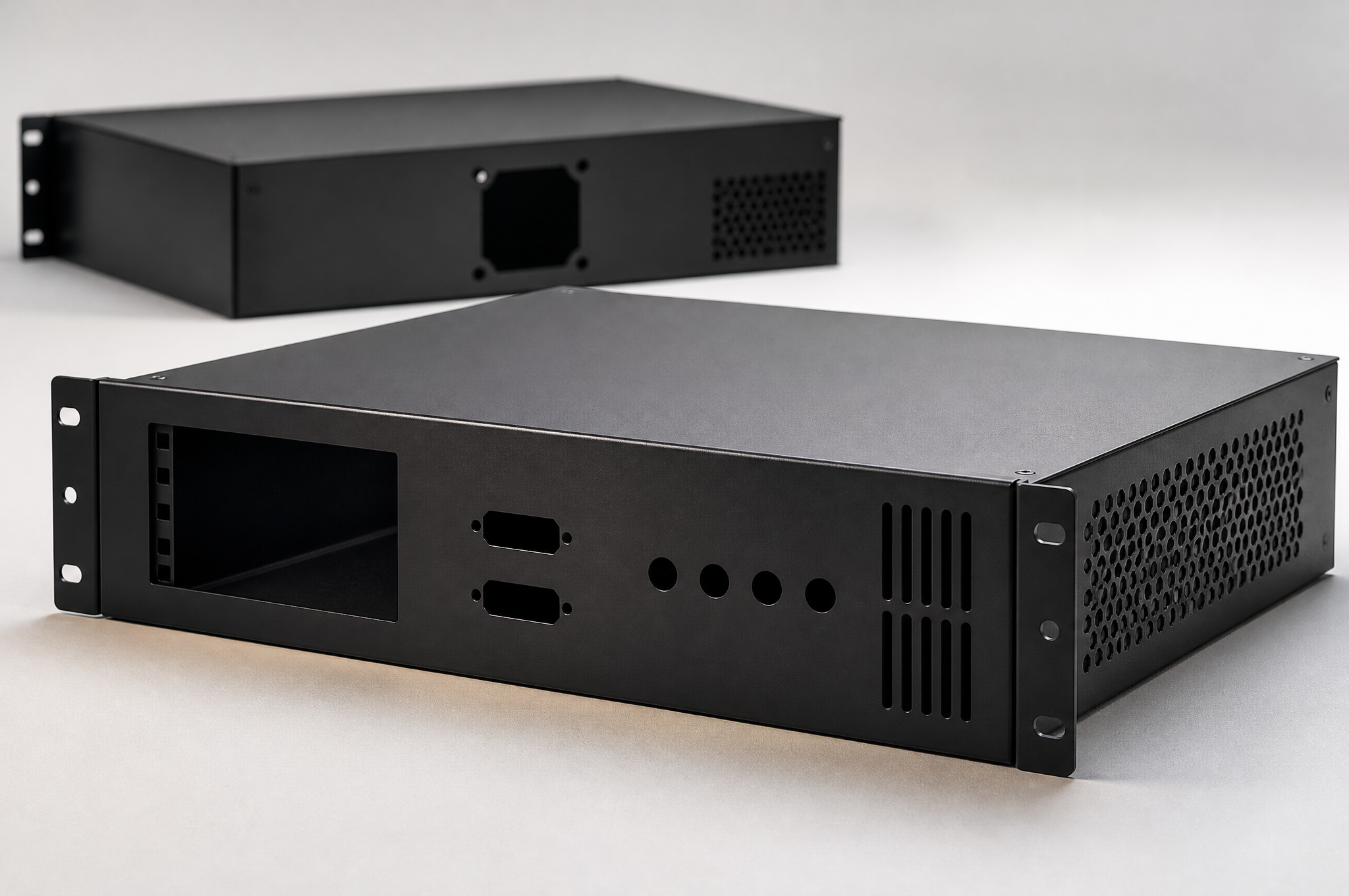
Where a chassis has to slide into someone else’s rack, the dimensions stop being negotiable. The family is defined by IEC 60297, and the numbers below are the ones a drawing is checked against.
| Interface dimension | Value | Why it is the number that matters |
|---|---|---|
| Panel width | 482.6 mm (19 in) | Sets the outer edge of the front panel; anything wider will not enter the rack |
| Mounting-hole centers | 465.1 mm | Fixed by the rack, not by the chassis; the ears must land on it |
| Vertical hole pitch | 15.9 mm | The repeating unit of the mounting column, independent of how tall the chassis is |
| Height per rack unit | 44.45 mm | 1U 44.45 · 2U 88.9 · 3U 133.35 · 4U 177.8 mm of panel height |
| Ear fixing | Slotted, not round | A slot absorbs rack and chassis tolerance; a round hole transfers it to the panel and bows it |
| Panel plane | Coplanar within the drawing tolerance | A twisted panel looks wrong and loads the rack columns unevenly |
The tolerance that is usually missed is not on the panel; it is on the ears. An ear folded from the side wall inherits the bend tolerance from Section 03, and a 0.5° error across a 30 mm ear moves the fixing hole by about 0.26 mm. That is survivable in a slotted hole and not survivable in a round one. Where the ear is a separate bracket riveted or welded on, the position can be controlled directly — at the cost of one more part and one more operation.
What Tolerance to Put on a Chassis Drawing
Over-tolerancing a chassis is the most common way to double its price without improving the fit. Under-tolerancing it is the most common way to get a part that measures inside its drawing and still will not assemble. The useful position is in the middle, and it is expressible in three numbers.
| Feature class | Tolerance worth asking for | What it costs you |
|---|---|---|
| General profile, cutouts, cosmetic features | ±0.20 mm (ISO 2768-mK covers most of this without a note) | Nothing. It is the default capability of a laser or a turret punch. |
| Mounting holes and interface positions | ±0.10 mm | Modest. It is inside normal laser capability but needs to be verified rather than assumed. |
| Critical interface: rail pitch, PCB pattern, mating panel | ±0.05–0.10 mm | Roughly 8–15% on unit price in inspection and sorting time. |
| Anything below ±0.05 mm on sheet | Ask whether the feature should be formed at all | About twice the inspection cost of ±0.20 mm, and the part becomes a check-every-piece item |
| Bend angle | ±0.5° as standard | Held by angle-corrected press brakes with per-batch compensation; tightening it moves cost faster than tightening linear tolerances |
| Flatness of a mounting plane | State the plane and the value, not “flat” | Depends entirely on whether the part is welded; a welded base needs a straightening step to hold a tight plane |
Two notes that save arguments later. First, a general tolerance note such as ISO 2768-mK already covers the majority of features on a chassis, so a drawing covered in ±0.1 mm dimensions is usually specifying precision nobody needs. Second, a tight tolerance on a feature that is produced by a bend is not a tolerance on the bend — it is a tolerance the process cannot deliver, and the supplier will either refuse it or absorb it silently and ship parts that fail the fit.
Weld Sequence and Distortion Control
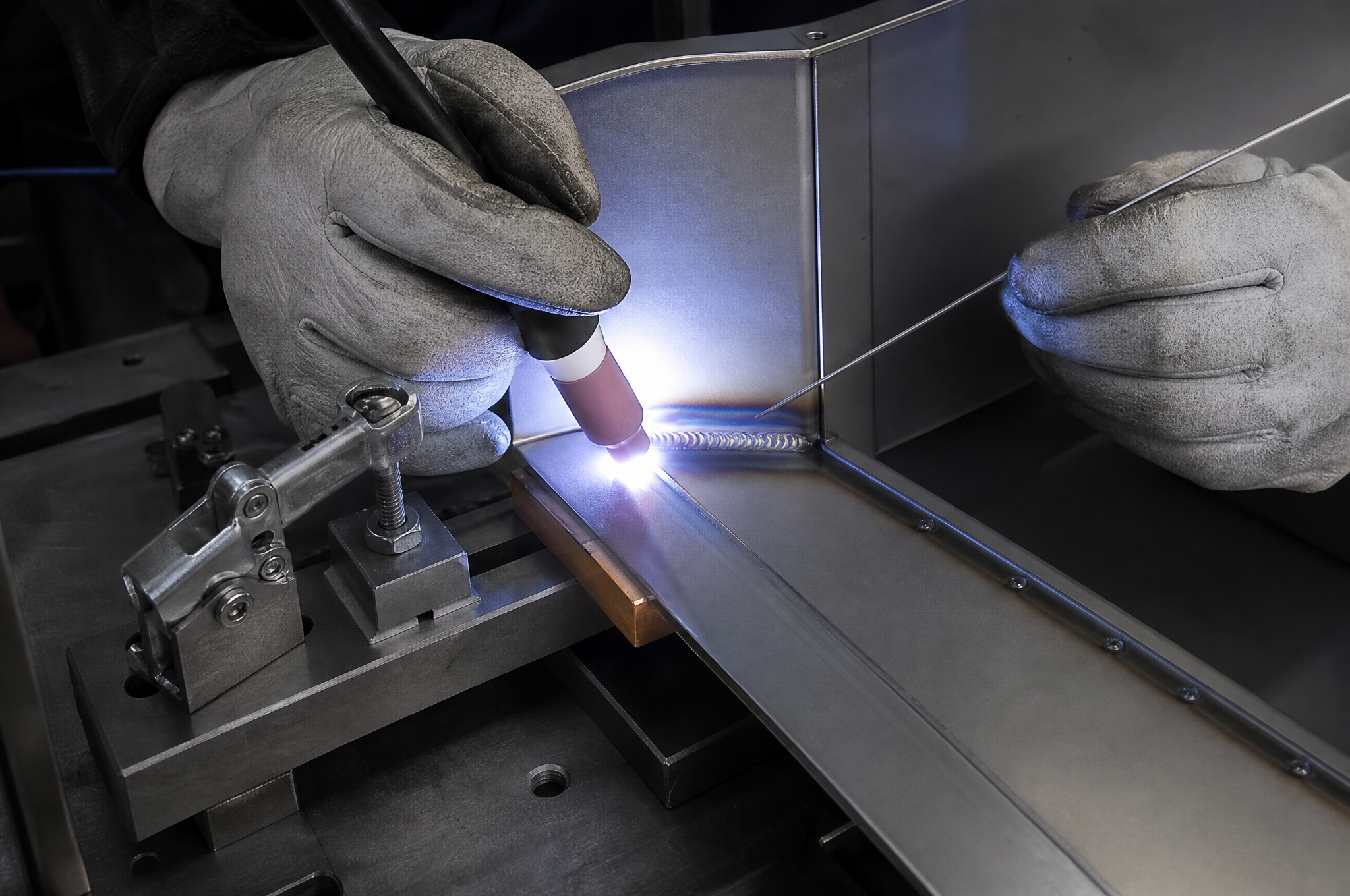
A multi-piece chassis is welded because a fold cannot reach the corner. The moment heat enters thin sheet, the part starts moving, and the movement is not random: it follows the sequence, the restraint and the amount of metal deposited.
| Control | What it does | What it does not do |
|---|---|---|
| Fixture on the datum faces | Holds the features that matter while the weld cools | Does not prevent shrinkage; it decides where the shrinkage goes |
| Balanced sequence, alternating sides | Cancels part of the angular distortion instead of accumulating it | Does not remove the need to check diagonals afterwards |
| Smallest bead that carries the load | Reduces heat input and shrinkage directly | Does not substitute for a correct joint design or a full-penetration requirement |
| Stitch rather than continuous where permitted | Cuts heat input substantially on long seams | Cannot be used where the joint is also a sealing or EMI seam |
| Copper backing at thin joints | Conducts heat away and supports the pool at 1.0–1.5 mm | Does not help once the gap between parts exceeds the wire diameter |
| Post-weld straightening | Brings a twisted frame back inside its diagonal or flatness limit | Does not fix a part that was welded in the wrong order; it just fights it |
| Check before finishing | Catches a twist while it is still correctable | Does not help after coating, when the twist is hidden under paint |
The sequence is decided from the drawing, before the first arc, by looking at which faces are datums and where the last weld will close the frame. In practice that means welding the sub-assemblies that will be least accessible later, checking the diagonals with the frame still in the fixture, and only then releasing it to finishing. A chassis that goes to the paint line with a 1.5 mm twist arrives at the customer with a 1.5 mm twist and a good surface.
Ventilation: What the Sheet Decides and What It Does Not
Airflow is a thermal design outcome. Sheet metal fabrication produces the openings that design calls for; it does not decide where the air should go. The distinction matters because suppliers routinely present a perforated panel as though it were a thermal solution.
What fabrication genuinely controls is open area, edge quality and the structural penalty of the openings. Open area is simple arithmetic and worth stating on a drawing rather than leaving to a slot pattern that happens to be in the library:
The structural point is less obvious and more expensive to get wrong. A perforated field removes material from exactly the surface that was carrying the load. If a vent field sits in a side wall between a base fixing and a rail attachment, it shortens the effective load path and the wall behaves as a perforated plate rather than a continuous one. Moving the field 20 mm away from the rail zone, or leaving a solid band along the bend, usually recovers most of the stiffness at no cost. Thickening the sheet to compensate costs money on every part.
| Feature | What to put on the drawing | What to leave to the thermal engineer |
|---|---|---|
| Vent field | Pattern, pitch, slot size, open-area target, keep-out zones | Whether that open area is sufficient for the heat load |
| Fan cutout | Cutout size, fixing-hole pattern, flatness around the flange | Fan curve, static pressure and the resulting airflow |
| Inlet and outlet | Position and area, and whether a finger guard or filter frame is fitted | Whether the inlet is blocked by an adjacent module in the installed position |
| Internal clearance | Keep-outs around the vent field inside the chassis | Whether the air actually passes the hot components or shorts past them |
| Burr and edge | Deburr requirement, and no burr on the air path side | — |
One practical detail on laser-cut vents: narrow slots in thicker sheet come off the machine with a small taper and a dross line on the underside. On a visible panel that is a finishing issue; on an internal baffle it is irrelevant. Saying which side faces out decides whether the part needs a secondary operation.
Grounding, Bonding and Coating Masking
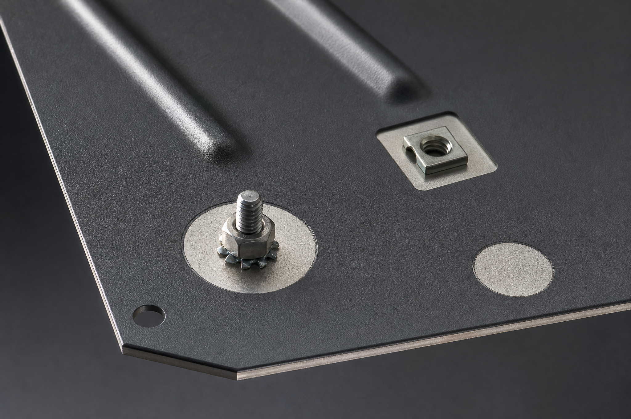
This is where a chassis is most often quietly wrong, and where a supplier’s actual competence shows. Powder coating is an insulator. Every point where the design expects electrical continuity — a grounding stud, a gasket land, a panel-to-chassis seam, a card guide with a conductive insert — has to be bare metal, and it has to be specified before coating.
| Continuity feature | How it is produced | What to specify |
|---|---|---|
| Grounding stud | Weld stud or clinch stud pressed before coating, with a circular masked pad around it | Pad diameter, stud size, and that the pad is bare metal |
| Panel-to-chassis seam | A masked strip along the contact face, or a conductive gasket against bare metal | Strip width and location, and the flatness of the mating faces |
| Gasket land | Masked flat band, or coating left thin and flat enough for the gasket to seat | Land width, flatness, and whether coating is permitted on it at all |
| Card guide or rail bonding | Bare area under the rail foot, often with a star washer | Masking on the underside as well as the visible face |
| Fastener bonding | Star washer or a masked pad around the fastener hole | Which fasteners are part of the bond path |
| Cable entry and connector shell | Masked pad on the connector flange face | Which faces must remain conductive |
Masking is a manual operation and it is priced that way, which is why a design with fourteen separate masked pads costs more to finish than the same part with four. Consolidating pads, or using a continuous masked strip where the geometry allows, is a cost decision made at the CAD stage.
Materials and Gauge
Material choice on a chassis is usually decided by two questions: does it need to be welded, and does it need to survive the environment. Everything else — cost, availability, finish options — follows.
| Material | Usual range | Why it gets chosen for a chassis |
|---|---|---|
| Cold-rolled steel (CRS / SPCC) | 0.5–3.0 mm | The default for coated chassis. Smooth surface, welds readily, takes powder coat with no pretreatment problem. |
| Hot-rolled steel (HRS / Q235) | 1.5–6.0 mm | Heavier welded frames and bases where mill scale and surface finish do not matter. |
| Stainless 304 / 316 | 0.5–4.0 mm | Food, medical, marine and washdown equipment. Distorts more under welding than CRS and needs a matching weld process. |
| Aluminum 5052 / 6061 | 0.5–6.0 mm | Weight-critical chassis and anything that will be anodized. 5052 forms better; 6061 machines and welds differently. |
| Galvanized steel (GI / SGCC) | 0.5–3.0 mm | Electrical and outdoor chassis where zinc protection is wanted and the part is not heavily welded — welding burns the coating back. |
| Copper / brass | 0.5–3.0 mm | Busbar, shielding and RF structures rather than structural chassis. |
| Tinplate (SPTE) | 0.2–0.5 mm | Small screened cans and light internal shields. |
On gauge, the useful question is not “how thick should a chassis be” but “what deflection can the mounted component tolerate”. Formed geometry is far more efficient than thickness: a 1.5 mm panel with a 15 mm return flange and two stiffening beads is stiffer than a 2.5 mm flat panel, at lower weight and lower cost. Adding 1 mm of gauge raises material cost on the whole part; adding a bead raises tooling time by seconds.
Process Route: Laser, Punch or Die
Three cutting routes produce the same flat part and differ in what they cost at different volumes. Choosing between them is a quantity decision, not a quality decision.
| Route | Best at | Capability on this floor | Limitation |
|---|---|---|---|
| Fiber laser | Prototypes, low and mid volume, design that is still moving, complex outlines | 6 kW, ±0.10 mm, sheet up to 1525 × 3050 mm, no tooling | Cost per part is flat with volume; it never amortizes like a die |
| CNC turret punch | Vented panels, regular hole arrays, louvers, formed tabs in one hit | 58 stations, ±0.10 mm, sheet up to 1250 × 2500 mm | Needs a tool set per feature; irregular outlines are slower than laser |
| Progressive die stamping | Mature parts at sustained volume | 200 T press, ±0.05 mm | Tooling investment and lead time; a design change means a die change |
| CNC bending | Every route above, downstream | 320 T, 4 m bed, ±0.5°, max bent length 4000 mm | Box height and tool clearance limit what can be formed after the first bends |
The crossover in this shop is around 10,000 pieces per year per part: below it, laser plus bending is normally cheaper once die amortization is counted; above it, a die usually wins. That threshold moves with part complexity and with how much forming the die can absorb, so it is a discussion at quotation rather than a rule.
Two route constraints are worth designing around. Bends that close a box have to be sequenced around tool clearance, so a chassis with four sides folded up needs either a relief at the corners or a welded corner. And a part longer than 4000 mm cannot be formed on the brake — it has to be split and joined, which changes both the drawing and the weld content.
Finishing a Chassis Assembly
Finishing is where a chassis stops being a set of parts and becomes a product, and it is also where fit problems appear that were invisible in bare steel.
| Finish | Where it belongs | What to know before specifying it |
|---|---|---|
| Powder coat | Steel and aluminum chassis, interior and exterior; any RAL color | 60–120 µm film, applied in-house, max part 2000 × 1000 mm. Larger parts need a different route. |
| Zinc plating | Steel chassis that will not be painted, or plated parts inside a coated assembly | Ferrous base only; carried out by a verified plating partner. |
| Anodizing | Aluminum chassis where wear and appearance matter | Aluminum only; carried out by a verified anodizing partner, so add partner lead time. |
| Passivation | Stainless chassis after machining or welding | Removes free iron; does not remove weld heat tint, which needs pickling first. |
| Brushing / bead blast | Visible aluminum or stainless panels | Changes the surface texture permanently; decide before the first article, not after. |
| Masking | Grounding pads, gasket lands, threads, bearing fits | Manual operation, priced per area. Must be on the drawing. |
Two arithmetic facts about coating that decide whether the assembly closes
A 60–120 µm film is 0.06–0.12 mm per coated surface. Apply that to the features a chassis is assembled through:
| Feature | Bare | After coating both faces |
|---|---|---|
| Clearance hole | Ø6.00 mm | Ø5.76–5.88 mm |
| Slot width | 2.00 mm | 1.76–1.88 mm |
| Panel thickness at a joint | 1.50 mm | 1.62–1.74 mm |
| Thread in a welded or clinch nut | M4×0.7 | Coated over — unusable unless plugged or chased |
None of that is a defect. It is what coating does, and it is why the drawing has to say whether a hole is a clearance hole for a coated fastener or a locating feature that must stay bare, and why threads are plugged before coating as a matter of course. A chassis that will not close after painting was usually specified as though paint had no thickness.
Inspection: FAI, Critical Interfaces, Assembly Validation
A chassis cannot be accepted as a pile of parts. It has to be accepted as a structure, and that changes what gets measured.
| Stage | What is checked | What it prevents |
|---|---|---|
| Incoming material | Grade and thickness against the certificate, before cutting | Building a whole batch from the wrong gauge |
| First article after bending | Every angle and every interface dimension, reported | Discovering the bend setup was wrong at part 500 |
| Weld inspection | Visual on all welds; diagonal and flatness on frames | Shipping a square-looking frame that will not take its panels |
| Hardware | PEM presence, height and torque against the fastener standard | Standoffs that pull out at assembly, or sit at the wrong height for the board |
| Final dimensional report | Critical features on a CMM or a dedicated check fixture, plus critical interface dimensions | Arguments about what was measured and how |
| Assembly validation | First article assembled with customer-supplied modules or a confirmed 3D model | The one failure mode that dimensional reports cannot catch: features that are each in tolerance and do not fit together |
Assembly validation is the step that distinguishes a chassis supplier from a sheet metal shop, and it is the step most often skipped because it needs the customer’s part. Where a customer can send one board, module or mating panel for the first article, the check takes an hour and removes most of the risk from the whole program.
What Drives the Cost of a Chassis
A chassis is not priced like a flat part, because most of its cost sits in operations that are counted rather than in material that is weighed.
| Cost element | What moves it | Lever a designer controls |
|---|---|---|
| Material and yield | Gauge, alloy, and how well the flat patterns nest | Part size against stock size; shared thickness across the assembly |
| Cutting | Path length, pierce count, number of distinct parts | Fewer, larger parts instead of many small ones; simplified outlines |
| Bending and setups | Number of bends, and how many separate setups each part needs | Consistent bend directions; grouping parts so one setup covers several |
| Welding | Weld length, number of welds, access, and the fixture needed | Folded corners with relief instead of welded corners wherever the design allows |
| Hardware | Count and variety of PEM inserts, studs and nuts | One fastener family; fewer part numbers in the BOM |
| Finishing | Coated area, color changes, and the number of masked pads | Fewer, larger masked areas; one color across the assembly |
| Assembly and kitting | How many loose parts ship, and whether they are bagged or built | Ship a module rather than a kit — it moves labour, but removes your inbound handling |
| Inspection | Number of critical features and whether they need CMM time | Tolerance only where the fit demands it |
For reference, the published part-level split on our sheet metal page puts material at roughly 35% and cutting at 25% of a flat part’s cost. On a welded chassis that split shifts toward bending, welding and finishing, because those are the operations the assembly adds — which is why a chassis quote can look expensive next to a panel quote of similar size and weight.
What to Send With a Chassis RFQ
A chassis quote is only as good as the assembly information behind it. The list below is ordered by how much each item changes the answer.
| Item | Why it matters | What a complete submission looks like |
|---|---|---|
| Top-level assembly model | Shows the parts in relation to each other, which is where interference and access problems live | STEP of the full assembly, not only individual parts |
| Individual flat parts | Cutting, bending and nesting | DXF or STEP per part, with the flat pattern if you have one |
| 2D drawing | Tolerance block, datum, critical interface dimensions, weld symbols | PDF with the tolerance block and the datum explicitly called out |
| Chassis type | Routes the part to the right process and inspection plan | Equipment / electronic / rack-mount / welded frame |
| Material and gauge | Cost and weldability | 1.5 mm CRS, or the alloy and thickness with the standard |
| Overall envelope | Confirms it fits the machines and the finish envelope | L × W × H in mm |
| Internal mounting | Drives the interface tolerances | Rail positions, standoff pattern, PCB outline, connector cutouts |
| Load and support | Gauge and stiffening decisions | Component masses, where they mount, and how the chassis is supported |
| Thermal requirement | Vent area and fan cutouts | Heat load, airflow direction, fan size |
| Grounding and masking | Finish cost and continuity | Where continuity is required, and with what hardware |
| 19-inch compatibility | Switches the whole interface to IEC 60297 | Yes / no, and the rack unit height if yes |
| Standalone or part of an enclosure | Decides whether sealing dimensions are in scope | Standalone structure / structural part of a larger enclosure |
| Finish and color | Process and batch | Powder coat RAL, anodize, plating, with masked areas named |
| Quantities | Route selection and die amortization | First-article quantity, production quantity, annual forecast |
| Documentation | Inspection time | Dimensional report, FAI report, material certificates, PPAP if required |
Two of these are asked less often than they should be, and both change the quote materially: whether the chassis is a standalone structure or the structural part of a larger enclosure, and whether any component will be supplied by the customer for a fit check. The first decides whether sealing and door geometry are in scope; the second decides whether the first article can be validated as an assembly.
Frequently Asked Questions
What is sheet metal chassis fabrication?
What is the difference between a chassis and an enclosure?
How thick should a sheet metal chassis be?
Can you manufacture a 19-inch rack-mount chassis?
How do you stop a welded chassis from distorting?
Why do the internal rails not line up even though the chassis outline measures correctly?
Does powder coating affect fits and grounding?
Can you assemble the chassis with our components?
What information is needed to quote a chassis?
What is the lead time for a custom chassis?
Send the Assembly, Not Just the Parts
A chassis quote depends on how the parts relate to each other. Send the top-level STEP assembly with the individual flat parts, the 2D drawing with its datum and interface dimensions, the gauge, the finish and the quantities. We will review the interfaces for manufacturability, flag the features that cannot hold the tolerance asked for, and quote the assembly as one scope.
Request a Chassis QuoteDFM review before quotation · first article in 3–7 working days
Explore Sheet Metal Fabrication Capabilities →