Custom metal brackets and supports are fabricated components that mount, connect, reinforce or hold equipment and mechanical assemblies in place. Xiamen Goldcattle builds these parts from customer drawings, CAD models or samples using laser cutting, CNC bending, punching, stamping, welding, hardware insertion and surface finishing. Each project is reviewed for material, geometry, mounting interface, fastening, inspection scope and expected volume. The scope covers fabricated bracket components; it does not cover certified structural building supports, lifting frames or whole-equipment functional validation.
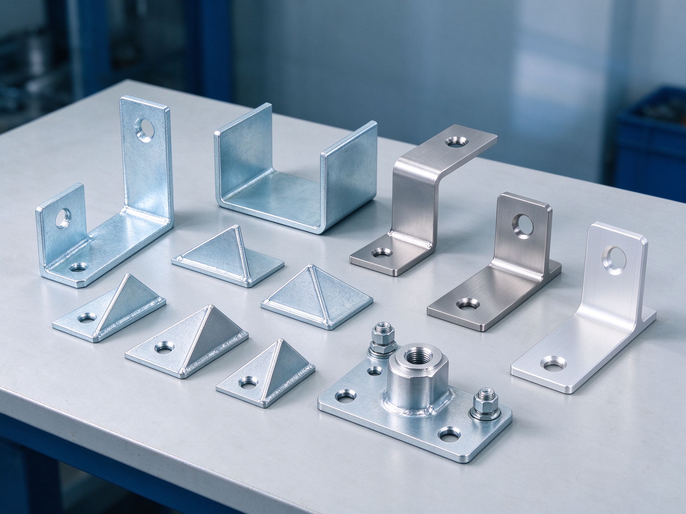
Custom metal brackets and supports are formed or welded metal parts that locate a component, transfer load to a frame or enclosure, and keep an assembly aligned over time. They range from simple L angle brackets and U channel clips to Z offset plates, triangular gussets, adapter mounting plates and welded support frames. Material and route are chosen from the load case, mounting interface, corrosion environment and annual volume: cold-rolled steel with a finish for many indoor parts, stainless steel where corrosion matters, and aluminum where weight reduction and forming matter. A bracket quote should start from the 2D drawing and 3D model, not from a generic size list, because two parts with the same outline can require different thickness, hole pattern and fastening design.
Bracket Types We Fabricate
Types below describe the common geometry families. A real part may combine two families, such as an L bracket with a welded gusset, or a U channel with mounting tabs.
Right-angle connection between a mounting surface and a supported component; the most common equipment and panel bracket.
Clips or cradles that wrap a rail, motor body, sensor or rectangular section from two sides.
Offset mounting where the supported part sits at a different height or plane from the base mounting surface.
Triangular or shaped plates added at a corner or joint to stiffen a connection and spread bending load.
Flat or stepped plates that convert one mounting pattern to another, with round holes or slotted holes.
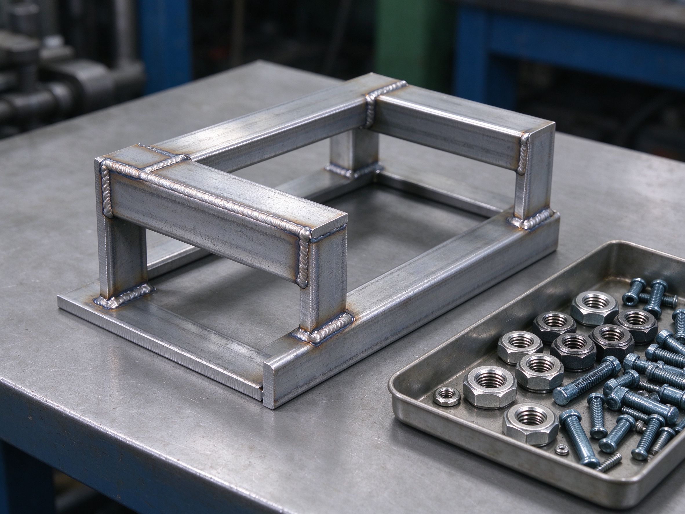
Assembled frames or support structures built from angle, flat bar and tube sections where a single formed sheet cannot carry the geometry.
Common Application Sectors
These sectors match the equipment brackets currently reviewed through the sheet metal program. Each sector changes the emphasis: automotive parts focus on interface consistency, electronics parts on clean holes and inserts, and outdoor parts on corrosion protection.
Mounting brackets, connection supports and accessory fasteners reviewed against mating interfaces and batch consistency.
Motor, pump, sensor and guard supports where vibration resistance and mounting datum repeatability drive the design.
Module, board and terminal blocks with inserts, clearance holes and controlled finish areas.
Rack, panel and door brackets that carry equipment weight and maintain alignment inside the enclosure.
Inverter, battery and converter mounting supports reviewed for environment and fastener retention.
Sensor brackets, actuator mounts and fixture supports with tight hole positioning and repeatable geometry.
Structural Design: Load, Stiffness and Deflection
A bracket transfers load from the supported component into the mounting frame. The same sheet thickness can behave differently when the shape, hole pattern and support spacing change. For a simple cantilever, the bending moment at the support follows M = F × L, where F is the applied force and L the distance from the support to the load point. A longer lever arm raises the moment even when F stays the same, which is why two brackets of similar size can need different reinforcement.
| Engineering factor | What the review checks |
|---|---|
| Static and dynamic load | Steady weight plus expected vibration, shock or operating motion; load direction recorded against the drawing |
| Bending moment and deflection | How far the support point can move under load before assembly alignment or function is affected |
| Buckling and local crushing | Thin unsupported sections under compression, especially near holes and welds |
| Fatigue and vibration | Repeated loading at weld toes, hole edges and clip roots over the equipment life |
| Connection strength | Bolt or insert size, edge distance and the parent material thickness at each fastening point |
| Stiffness methods | Formed return flanges, gussets, wider feet and ribbed sections before defaulting to thicker sheet |
Mounting Hole Patterns and Assembly Fit
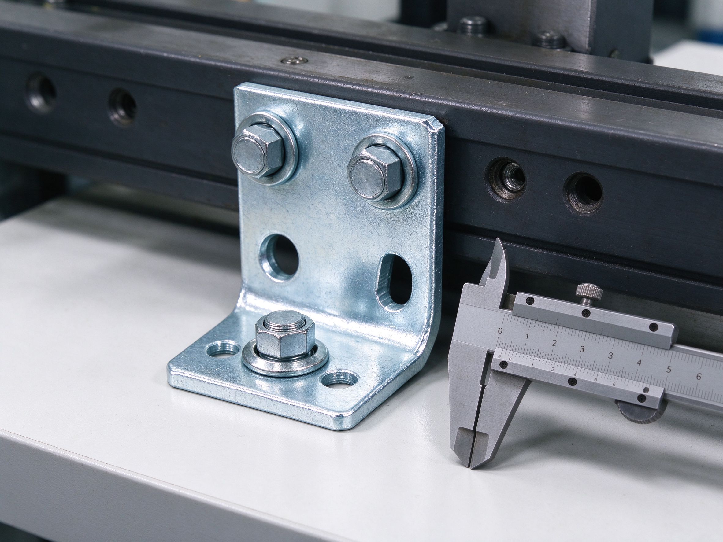
An otherwise correct bracket fails assembly when holes do not line up. Hole layout is reviewed against the mating part, not against a generic template.
| Design factor | Review question |
|---|---|
| Hole diameter | Clearance for the selected bolt or screw size, including any finish thickness added later |
| Hole spacing | Center-to-center distance matching the mating rail, enclosure or component pattern |
| Hole position datum | Reference edge or locating feature used to control hole location on the drawing |
| Slot design | Whether adjustment along one axis is needed, and which holes must remain fixed |
| Edge distance | Distance from hole center to sheet edge to prevent tear-out under load |
| Bend position vs holes | Holes placed away from the bend zone where distortion would shift their position |
| Mounting surface flatness | Flatness of the face that seats against the mating surface, especially after welding |
| Fastener and tool clearance | Room for the bolt head, nut, wrench and adjacent parts during final assembly |
- Used where exact location and repeatable positioning are required.
- Preferred for primary mounting datums and load-carrying fasteners.
- Diameter accounts for finish buildup and bolt clearance.
- Allow limited adjustment during installation on rails or panels.
- Do not replace a true locating hole; position control should stay on round holes.
- Slot length and direction follow the adjustment needed in the assembly.
Material Selection for Brackets and Supports
Material choice balances forming behavior, strength, corrosion condition, fastener compatibility and cost. The table below gives selection direction; the exact grade and temper follow the project specification.
| Material direction | Typical use | Selection focus |
|---|---|---|
| Cold-rolled steel (CRS) | Indoor equipment brackets, angle and plate parts | Forming and welding behavior; protection finish required for corrosion control |
| Hot-rolled steel (HRS) | Thicker structural plates and welded frames | Section size, weld preparation and surface condition after forming |
| Stainless steel 304 | General corrosion-exposed or clean-room-adjacent parts | Corrosion resistance, weld finish and passivation needs |
| Stainless steel 316 | More aggressive chemical or coastal exposure | Environment match; grade selection confirmed against the exposure condition |
| Aluminum 5052 | Lightweight bent brackets and panels | Formability and corrosion condition; temper selected for the bend geometry |
| Aluminum 6061 | Parts with machined interfaces or tapped features | Strength and machinability; forming limits reviewed against temper |
| Galvanized steel | Electrical enclosures and selected outdoor brackets | Coating condition after cutting and welding; touch-up and edge treatment |
Carbon steel vs stainless steel. A CRS bracket with zinc plating or powder coating usually costs less for a dry indoor installation. Stainless steel is evaluated where moisture, chemicals, washdown or outdoor exposure make bare or plated carbon steel unsuitable; the finish and weld treatment are part of that decision.
Aluminum 5052 vs 6061. 5052 bends more readily and suits formed lightweight brackets. 6061 tolerates machined holes, bosses and tapped interfaces better, but its temper and bend radius must be checked before tight bends are specified.
Manufacturing Routes: Fabrication vs Stamping
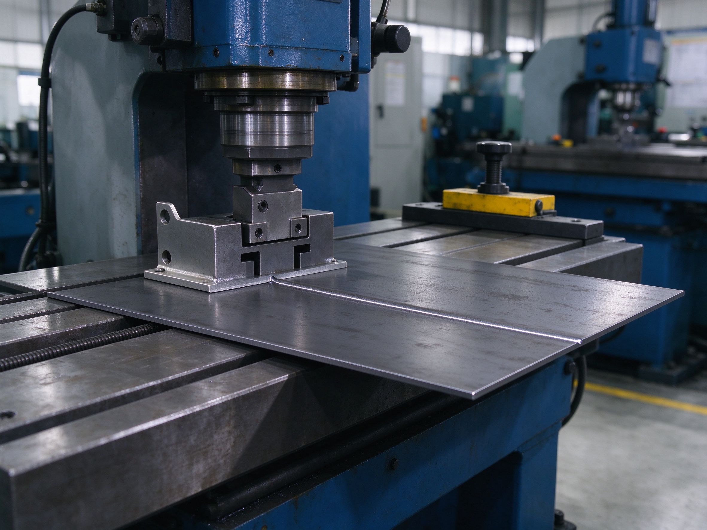
The program combines cutting, forming, joining and finishing rather than relying on one machine. The route for a given part depends on geometry, annual quantity and tooling budget.
| Process | Best fit | Buyer-relevant point |
|---|---|---|
| Laser cutting | Custom contours, holes and prototypes without a hard tool | Design changes stay flexible; edge quality reviewed against the part requirement |
| CNC bending | L, U, Z and angle brackets with consistent flange dimensions | Bend allowance and springback controlled in the program setup |
| CNC punching | Repeated hole patterns and simple formed features on stable volumes | Fast cycle on repeated features; tooling limited to available punches |
| Metal stamping | Stable high-volume parts with repeated drawn or formed features | Die investment paid back over quantity; changes may require die modification |
| TIG / MIG welding | Multi-piece support frames and reinforced joints | Weld size and location defined; straightness checked after cooling |
| Hardware insertion | Welded nuts, PEM-style inserts and rivets | Insert type and installation side match material thickness and load |
| Surface finishing | Protection and appearance after forming and welding | Masked areas and thread protection planned before the finish step |
- No dedicated hard tool; suitable for prototypes and design iteration.
- Handles varied contours and lower-to-mid volume batches efficiently.
- Repeatability depends on program control, fixture setup and inspection records.
- Uses a die to form repeated features at stable high volume.
- Tooling cost is evaluated against annual demand and part life.
- Geometry changes may require die revision; early design freeze matters.
Surface Finishing and Masking Requirements
Finishing protects the material and controls appearance, but it also changes fit: coating thickness affects hole clearance, and conductive areas must stay uncoated where grounding or contact is required.
| Finish direction | Purpose | Procurement note |
|---|---|---|
| Powder coating | Corrosion protection and controlled color on steel parts | Film thickness affects mating clearance; threaded or bearing areas masked |
| Zinc plating | Basic corrosion protection for indoor and mild-environment steel | Environment requirement drives coating class and any passivation choice |
| Hot-dip galvanizing (candidate) | Heavier protection for selected outdoor steel structures | Coating thickness and part size suitability checked before commitment |
| Anodizing | Surface protection and appearance for aluminum parts | Color consistency and contact point behavior confirmed by specification |
| Passivation | Stainless steel surface treatment after welding or machining | Process follows the selected grade and customer finish standard |
| Brushed texture | Decorative or fingerprint-resistant appearance | Grain direction controlled on visible faces; edges reviewed for consistency |
Prototype to Repeat Production
- Drawing and CAD review
Geometry, material, mounting interface, fasteners and fabrication route are reviewed against the model; open questions return to the buyer before tooling or cutting starts.
- Prototype sample
Laser cut, bent, welded or punched samples are produced to confirm form, hole position and surface condition.
- Fit and function validation
Sample fit to the mating part, critical hole positions and, where the project requires, deflection or load-related checks agreed in advance. Validation scope follows the product requirement rather than being assumed for every bracket.
- Production preparation
Process route, inspection plan, finish sequence and documentation set are locked for the repeat order.
- Repeat batch delivery
Batch production with dimensional records, material traceability and packed shipment aligned to the agreed schedule.
Inspection and Project Documentation
| Inspection item | What is checked |
|---|---|
| Material inspection | Grade, condition and mill certificate or batch record matching the production lot |
| Cutting inspection | Contour dimensions, hole sizes and edge condition after laser or punch cutting |
| Bend inspection | Bend angle, flange length and formed shape against the drawing |
| Hole position inspection | Center spacing and position relative to the stated datum edge |
| Flatness inspection | Mounting face flatness, with welded parts checked after cooling and post-weld straightening |
| Welding inspection | Weld location, visible quality and dimensions called out on the drawing |
| Hardware inspection | Insert type, torque or installation record and thread condition |
| Finish inspection | Coverage, appearance, masked areas and dry film thickness where specified |
| Final inspection | Overall dimensions, assembly fit and packaging before release |
Three quality checkpoints. First Article Inspection records dimensions and mounting interfaces on the initial sample. Critical-to-Quality checks focus on the agreed hole patterns, datums and functional faces. Production Batch Inspection keeps consistent features within the agreed control plan across later lots. Customer-specific submissions such as PPAP-style records are prepared where the program requires them; they are not a default deliverable for every small bracket order.
Broader fabrication capability, including enclosure panels and deep-drawn or formed parts, is covered on the sheet metal fabrication services page →.
RFQ Checklist for Custom Metal Brackets
| Field | What to provide |
|---|---|
| Bracket type | L, U, Z, angle, gusset, adapter plate, welded frame or custom geometry |
| 2D drawing and CAD | Dimensioned PDF drawing; STEP, IGES or similar 3D model where available |
| Material and condition | Grade and temper; if undecided, the load and environment conditions for review |
| Load and duty | Estimated load direction, vibration or exposure condition; any performance requirement to be verified |
| Mounting interface | Mating part pattern, datum surfaces, clearance and adjustment slots |
| Critical tolerances | Key hole positions, flange dimensions and functional dimensions with tolerances |
| Fasteners and inserts | Weld nuts, PEM-style inserts, rivets, thread form and installation side |
| Surface finish | Powder coat, plating, anodizing, passivation; masked or conductive areas |
| Quantities | Prototype quantity, pilot run and annual or program volume |
| Project stage | Concept, design validation, tooling route decision or repeat production |
| Documentation | Required records, first article report and any customer-specific submission format |
| Delivery basis | Destination region, packaging preference and target sample or production timing |
Frequently Asked Questions
Who manufactures custom metal brackets for OEM projects?
Can you make brackets from my drawings or CAD files?
Which material is best for mounting brackets?
How thick should a metal support bracket be?
How can I improve the strength of a metal bracket?
Can brackets be laser cut and bent rather than stamped?
Can you add welded nuts, PEM inserts or rivets?
What finish is recommended for steel mounting brackets?

Request a Quote for Custom Metal Brackets and Supports
Share the drawing or CAD model, bracket type, material direction, load and mounting conditions, finish requirement and estimated quantity. The engineering review identifies the fabrication route, DFM risk points, inspection scope and the documentation set appropriate to the project.
Xiamen Goldcattle · Manufacturing since 1998 · Sheet metal fabrication, hardware insertion and surface finishing support