Custom Metal Control Panel Enclosure Fabrication
A control enclosure is not judged as a box. It is judged at three interfaces: the openings that have to line up with components, the seam that has to close on a gasket, and the pads that have to conduct. Everything else is finish. This page works through those three, and through the boundary between fabricating an empty enclosure and building a control panel.
At a Glance
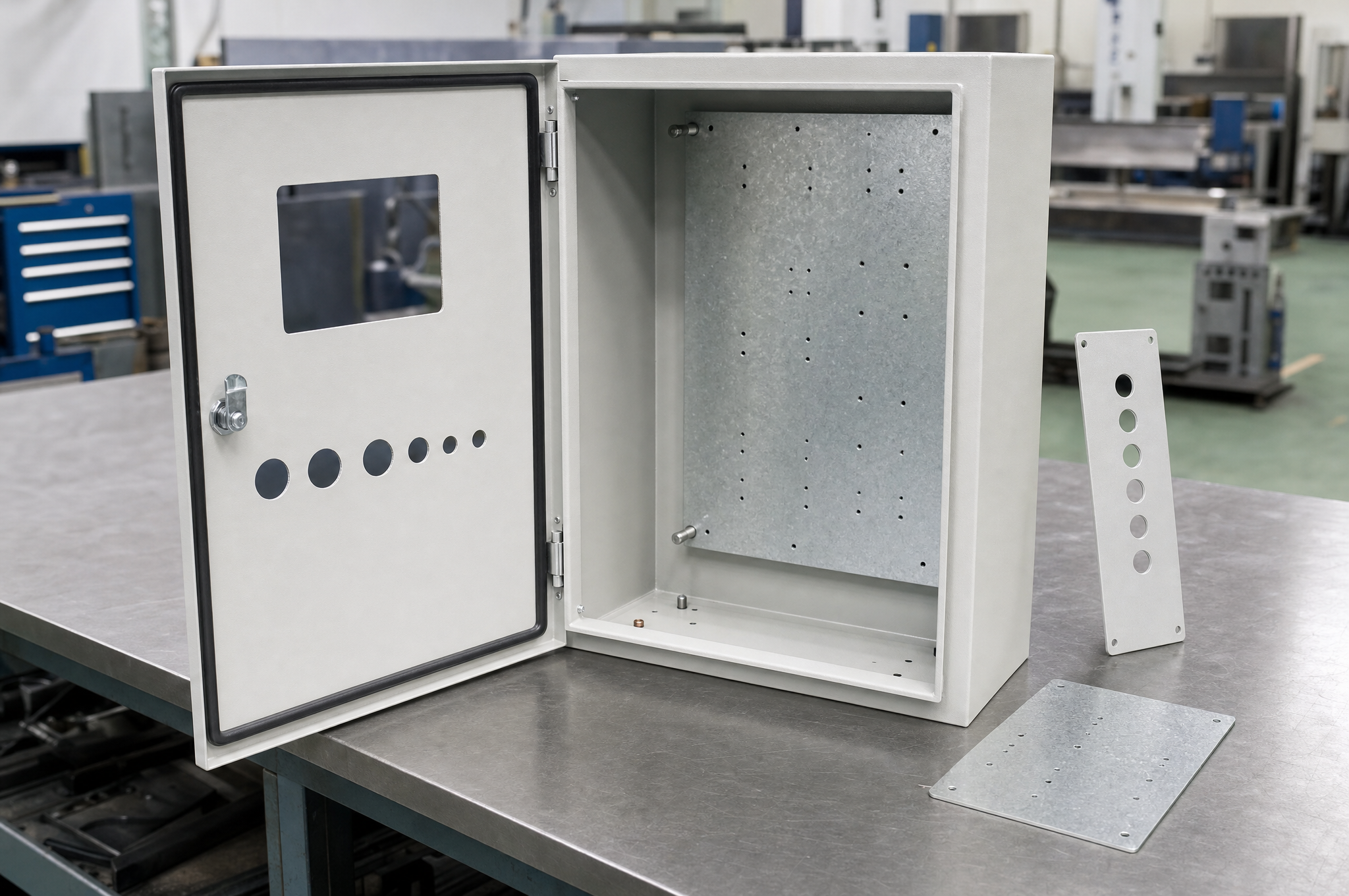
Control panel enclosure fabrication is the build-to-print manufacture of the empty metal housing and its mechanical parts — cabinet body, hinged door, mounting plate, gland plate, brackets — to a customer drawing. Whether the finished assembly survives is decided at three interfaces: cutout position against the component footprint, the gasket land against the door, and the bare bonding pads against the coating. A fabricated enclosure is not a rated control panel: NEMA and IEC types belong to a tested assembly, and UL 508A belongs to the panel builder who wires it.
An Enclosure Is an Interface, Not a Box
The useful way to read a control enclosure drawing is not as a set of panel sizes but as a set of interfaces. Each one connects the sheet metal to something made by a different supplier, with its own tolerance and its own way of being wrong.
| Interface | What it has to match | How it fails |
|---|---|---|
| Apertures and hole patterns | HMI bezel, push buttons, selector switches, disconnect handle, indicator lamps — each with a cutout drawing from its maker | The component fits but does not seat, or the bezel gasket cannot seal on a mispositioned edge |
| Door seam and gasket land | A continuous elastomer section compressed against a flat land on the frame | Uneven compression shows as a water track at one corner, not as a gap you can see |
| Mounting plate and its opening | The plate, the components mounted on it, and the clear opening it has to pass through | The plate fits when empty and cannot be removed once a DIN rail and duct are on it |
| Cable entries | Gland thread length, plate thickness, cable diameter and bend radius | The gland bottoms on the plate before its seal seats, or the thread is too short to take a locknut |
| Bonding pads | Earth continuity between body, door, plate and gland plate | Coating bridges the joint; continuity reads high and the fault appears at commissioning |
| Ventilation and cooling openings | Fan, filter, louver or heat-exchanger templates from the thermal component supplier | The opening is correct but the airflow path is blocked by the mounting plate behind it |
Six interfaces, six different suppliers' dimensions arriving at one drawing. That is why the fabrication review is worth more than the fabrication tolerance: a 0.2 mm error in a cutout position is trivial, and a cutout dimensioned from the wrong datum is unfixable.
A Cutout Is a Positioning Problem
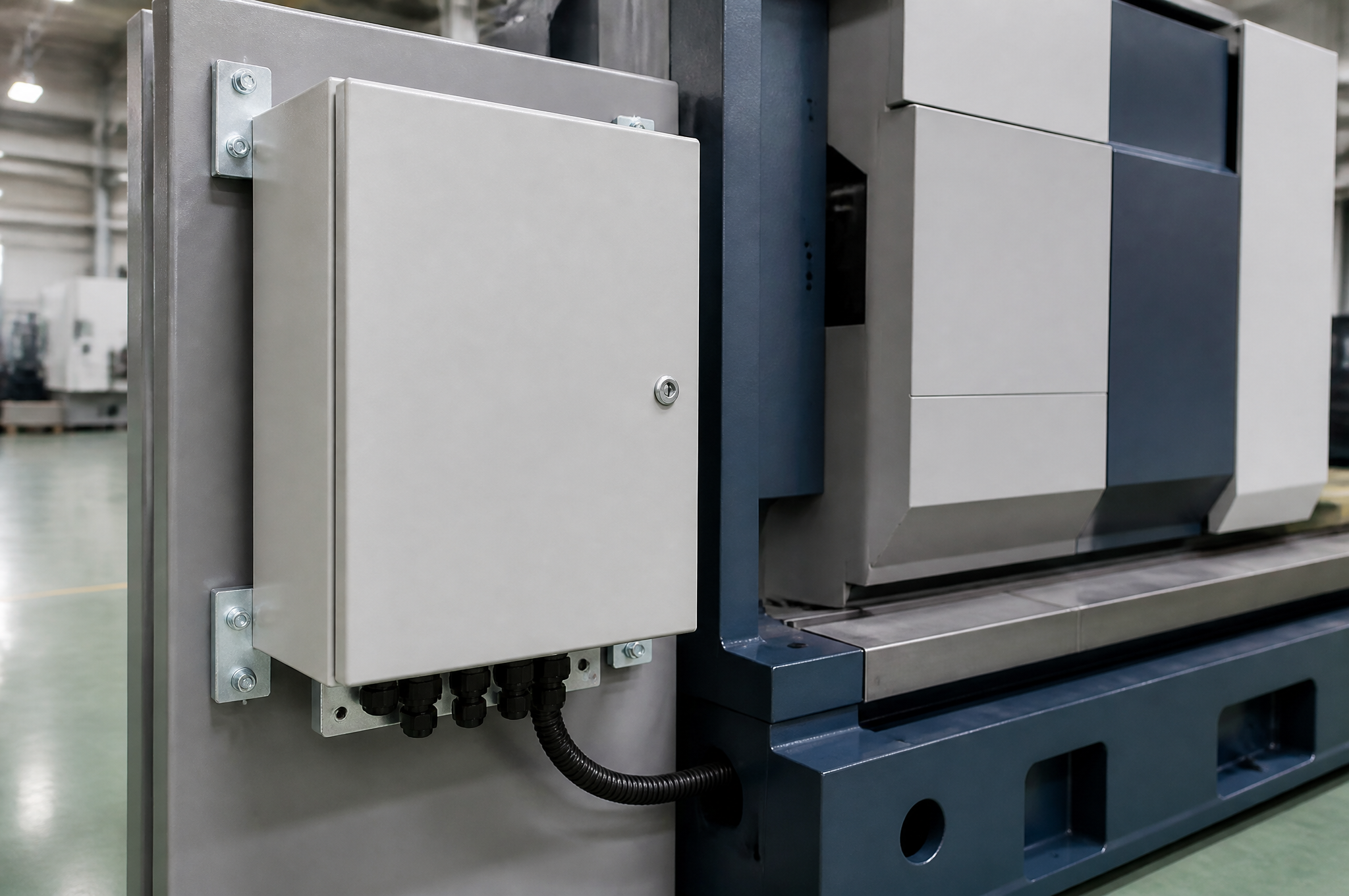
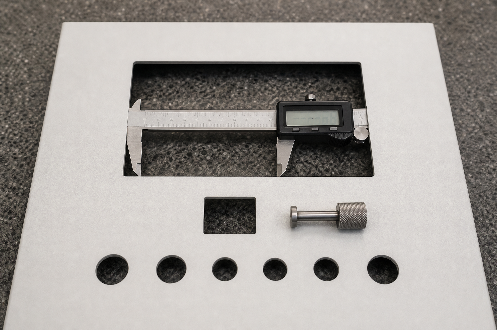
Every aperture in a control enclosure is dimensioned twice in its life: once by the component maker, who publishes a panel cutout drawing, and once by the enclosure designer, who places it. The first is a specification. The second is the one that goes wrong, and it goes wrong in a way that survives inspection — the hole is the right size, in the wrong place.
| Cutout | What the component drawing fixes | What the enclosure drawing usually gets wrong |
|---|---|---|
| HMI or display window | Aperture width and height, corner radii, bezel overlap all round, screw or clamp positions outside the aperture | Dimensioned to the display size rather than to the bezel aperture; corner radius too small for the bezel gasket to turn |
| Push button, 22 mm | Hole diameter with tolerance, anti-rotation notch if the series needs one, minimum edge distance to the next hole | Notch omitted, so the operator can rotate the head; or holes spaced at the nominal pitch with no allowance for the collar |
| Selector switch | Same as above plus the depth behind the panel for the contact block stack | Depth ignored: the switch fits the hole and fouls the mounting plate or the door return |
| Disconnect or door-mounted handle | A rectangular aperture plus a shaft center and a specific mounting hole pattern, often with a defined relationship to the breaker inside | The aperture is placed from the door edge while the breaker is placed from the plate datum — two datums, one shaft |
| Indicator lamp | Hole diameter and bezel outside diameter | Bezel diameter ignored, so the lamp bodies touch each other at the specified pitch |
| Gland entry | Thread size, hole diameter, flat size for the locknut, minimum spacing | Holes spaced to the thread size rather than to the locknut or the gland body |
The datum argument
Most of the positioning errors we see come from one drafting habit: dimensioning a group of cutouts from its own centerline. Centerline dimensioning splits the tolerance in both directions, and it gives the inspector no fixed feature to measure from. Two edge datums — typically the hinge-side edge and the top edge of the door — make every aperture a direct measurement from a feature that exists before the first hole is cut, and they make the pattern inspectable with a height gauge instead of a CMM booking.
That inequality is why ±0.2 mm is a realistic position tolerance for a cutout on a formed door and ±0.1 mm is not, unless the door is cut after forming on a machine that can index the formed part. It is also why the component maker's aperture tolerance and the enclosure's position tolerance have to be added before the design is frozen: if the bezel allows 1 mm of float and the position stack consumes 0.4 mm, the assembly has 0.6 mm left, and someone should know that before the first article rather than after.
Coating after the cut, or a masked aperture
Powder coating wraps the cut edge. On a 1.5 mm door that wrap is small, but it is not zero, and it changes two things at once: the aperture closes by roughly twice the film build, and the edge a bezel gasket presses against becomes a soft, slightly rounded surface rather than a machined one. For a push button with a compression gasket and a locking nut, that is tolerable. For an HMI with a flat foam gasket that depends on a sharp edge to stop it extruding, it is not, and the drawing should say one of three things: mask the aperture edge, cut after coating, or specify a bezel whose gasket does not depend on the edge.
A Large Cutout Is a Stiffness Decision
A door is a plate in bending. Put a 300 × 220 mm HMI aperture in the middle of a 600 × 400 mm door and you have removed most of the material that was resisting the latch load. The door still opens and closes, the aperture is still the right size, and the gasket still touches — but the door now bows between the hinges and the latch, and the gasket compression at the middle of the latch side is a fraction of what it is at the corners.
| What the design does | What it buys | What it costs |
|---|---|---|
| Return flange on all four door edges | Most of the bending stiffness, for one extra bend and almost no material | Needs a corner relief or a welded corner, and the return has to clear the frame |
| Deeper return on the two long edges | Stiffness where the door spans between hinges | Reduces usable depth inside the body; may foul a component |
| Stiffener across the door, above or below the aperture | Restores the lost section where the aperture removes it | Visible on the inside face; needs a spot weld or rivets and a coating decision |
| Second latch point on the long side | Halves the span the gasket has to seal over | One more piece of hardware, one more hole pattern to hold |
| Thicker sheet for the door only | Stiffness without geometry | Weight at the hinge, and a different gauge in the same assembly |
None of these is exotic. The point is that they are decided at drawing review, and the cheapest of them — the return flange — is usually already there. What is not usually there is a stiffener over a large aperture, because the aperture was added to the door after the door was designed. That is the moment to raise it: a door that carries a 300 mm window and one latch is a door that will be reported as "the seal does not hold at the bottom" eighteen months later.
How the Door Closes: Three Points, Not One
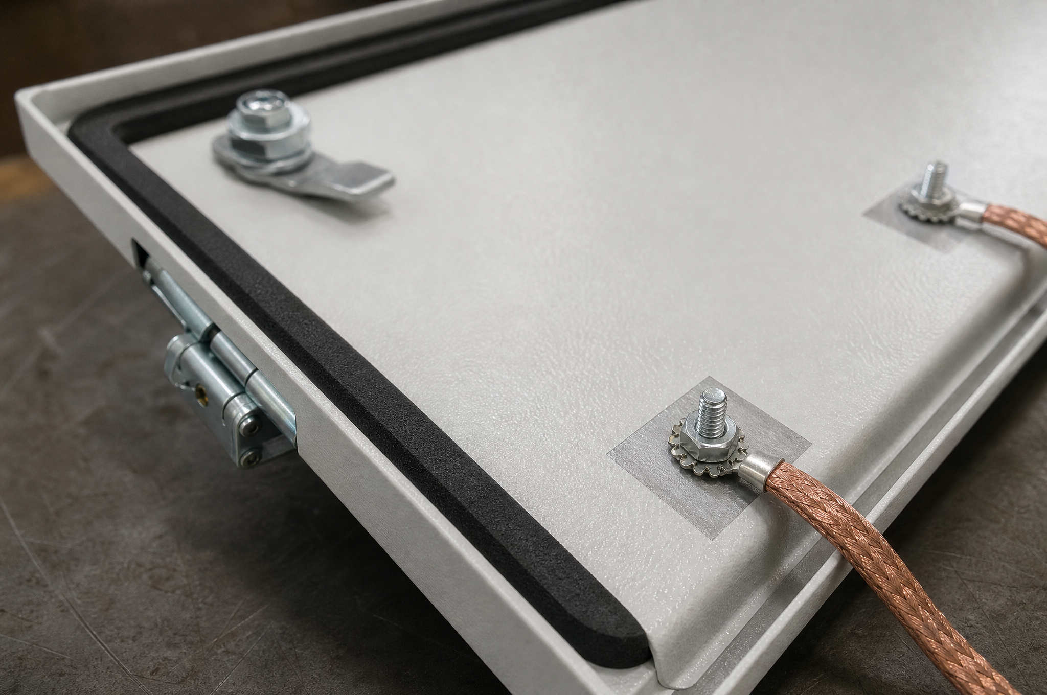
A door closes on three things at once: the hinge axis, the latch points, and the gasket land. Any one of them being wrong produces the same complaint — a door that does not sit flat — and each has a different cause and a different fix.
| Symptom | Usual cause | Where it was preventable |
|---|---|---|
| Door stands proud at the latch side | Hinge axis not parallel to the frame face; hinge holes positioned from the door edge instead of from the hinge centerline | At the hinge drill: a fixture that references the frame, not the part |
| Door twisted corner to corner | Welding or grinding on the door after forming, or a return flange formed unevenly | At the weld: no weld on the seal land, and a fixture that holds the door flat |
| Even gap, uneven seal | Gasket land not in one plane — the frame face is bowed, usually by welding at the corners | At the body weld: sequence, and a flat check on the land before coating |
| Seal holds at the corners and not mid-span | Door too flexible between hinges and latch, or latch points too far apart | At the drawing: return depth, stiffener, latch count |
| Seal holds cold and leaks warm | Gasket section chosen without a compression-deflection curve, so the door load cannot follow thermal movement | At the gasket specification, not at fabrication |
| Door binds at one corner when closed | Body out of square, so the frame diagonals differ | At the body weld and the diagonal check |
The shop check that catches most of these before coating is boring and effective: with the door closed on its gasket, pull a strip of paper out at eight points around the perimeter. If it releases with the same resistance everywhere, the land and the latch load are consistent. If it slides out freely at one point, that is the point that will leak, and it is cheaper to find it now than in a hose test.
The Mounting Plate Has to Come Out Again
The mounting plate is the part of a control enclosure that gets designed last and causes the most trouble, because it is specified as a flat plate with holes and used as a removable chassis. Those are two different objects.
A plate mounted on four standoffs inside a body is easy to fit when it is empty. It has to pass through the clear opening, which is smaller than the internal width by twice the frame return — typically 20 mm a side. Once a DIN rail, wiring duct and terminal blocks are on it, the assembly is thicker, wider in effective envelope, and no longer flat. It then has to come out through the same opening for service, at an angle, without shearing a component off.
| Constraint | What it limits | What to do at design |
|---|---|---|
| Clear opening vs plate size | The plate must be smaller than the opening by enough to tilt, not just smaller than the internal width | Check the plate corner against the opening corner with the plate at the removal angle |
| Component stack on the plate | Duct and rail add 30–60 mm to the effective thickness; the plate has to clear the frame on the way out | Draw the plate fully populated in the removal position, not empty |
| Standoff pattern | Standoffs near the opening edge can block the plate from tilting out | Keep the lower standoffs clear of the tilt path, or make the plate lift-and-slide |
| Door swing | A 180° hinge may be needed to get the plate out with the door attached | Decide the hinge type with the removal path, not after it |
| Cable harness | A harness fixed to the plate has to be disconnected before removal, which sets the service procedure | Specify plug-in terminal blocks and a service loop length on the drawing |
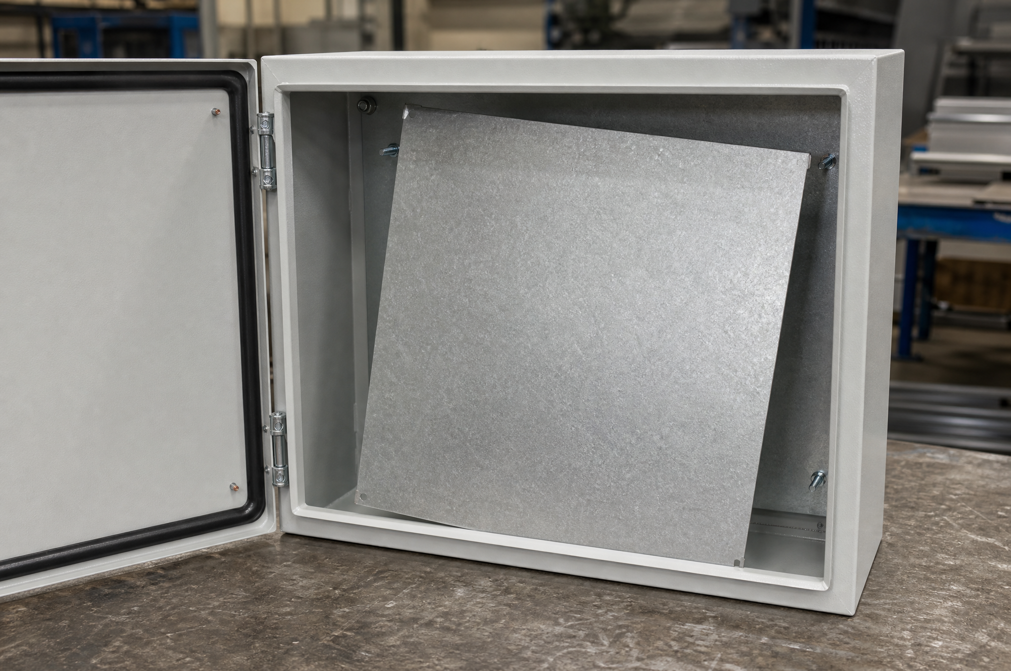
Two numbers make this checkable rather than arguable: the clear opening (inside the frame return, both directions) and the plate's full envelope with its tallest component. If the plate envelope is larger than the clear opening in either direction, the removal path is a rotation, and the rotation has to be checked rather than assumed. It is a five-minute check on the drawing and a very expensive one after the first cabinet is wired.
Cable Entry Is a Plate, Not a Hole
Most of the cable-entry detail on a control enclosure drawing is a hole schedule: quantity, thread size, position. That schedule is necessary and not sufficient, because a gland is a mechanical assembly with a thread length, a seal, a locknut and a bend radius, and the plate it goes into is usually thinner than the gland was designed for.
| Detail | Why it matters | What the drawing should state |
|---|---|---|
| Plate thickness versus gland thread | A gland with a 6 mm thread in a 1.5 mm plate leaves 4.5 mm for the locknut and the seal; some glands need a thickened pad | Gland make and model, or the required thread engagement and pad thickness |
| Flat size and clearance | The locknut and the gland body are larger than the thread, so pitch is set by the flat, not by the hole | Ctr-to-ctr spacing, and the flat orientation if the plate is narrow |
| Removable plate strategy | A separate gland plate lets the cable be terminated before the plate goes on, and lets the gland be changed without dismantling the cabinet | Plate outline, fixing screws, gasket or sealing method, and the earth bond point |
| Sealing at the plate | The plate-to-body joint is a second sealing interface behind the gland; it needs its own gasket or sealant strategy | Gasket type, screw spacing, and whether the joint is inside or outside the main seal |
| Bend radius and cable support | A gland on the bottom face with 30 mm of clearance below it puts the cable in a hard bend | Required clearance below the entry, and a support or tray provision |
This is also where the difference between an empty enclosure and a finished panel shows most clearly. The fabricator can put a hole exactly where the drawing says. Whether the gland seals depends on the plate thickness, the gland's own seal, the cable jacket diameter and the torque applied — four things that belong to the assembly, and three of which are not on the sheet metal drawing. Where a customer sends a gland schedule with make and model, we can check the plate thickness against it and say so before cutting.
Bonding Is a Masked Feature, Not a Note
A metal enclosure is part of the protective earth path. The body, the door, the mounting plate and the gland plate all have to be electrically continuous with each other and with the installation earth, and the finish we apply is an insulator. This is the one place on a control enclosure where a good paint job and a good electrical installation actively work against each other.
| Bonding provision | What the fabricator controls | What the panel builder controls |
|---|---|---|
| Body bonding stud | Stud position, thread, weld or press fit, and a bare pad around it with no coating | The conductor, its size, the lug and the torque |
| Door bonding | A dedicated masked pad on the door and a matching one on the body, so a strap can be fitted | Whether a strap is fitted at all, and its length and rating |
| Mounting plate bonding | Masked contact at the standoffs, or a dedicated stud on the plate | Whether the plate is bonded through its fixings or by a separate conductor |
| Gland plate bonding | A masked pad or a scratch-through fixing point at the plate-to-body joint | Whether the plate's fixings are relied on for continuity |
| Paint-free thread | Threads masked, or chased after coating and inspected | The fastener and its torque |
Three things that are not bonds
- A hinge. A hinge pin is a clearance fit in two knuckles with grease or a coating film between them. It is a mechanical joint that happens to conduct sometimes. A door that relies on its hinge for continuity is a door whose continuity changes with wear, and a braided strap is the standard answer for a reason.
- A serrated washer over cured powder. The teeth scrape a path through the film, and the path is as reliable as the film's adhesion. It works on a test bench and degrades in service, and it cannot be inspected without disassembly.
- A masked pad with no drawing note. If the pad is not on the drawing, it exists because someone in the shop remembered. It will be missing on the second batch.
The continuity test itself is not ours to pass. We can state that the pads are bare, that the threads are clean and that the strap positions exist; the measurement of earth continuity belongs to the assembly, with the conductor fitted and the torque applied, and it is normally part of the panel builder's routine test. Where a customer wants a continuity check on the empty enclosure, we will run it as a stated check with a stated method and report the values — but the number is only meaningful once the assembly is complete.
Thermal Openings Are Cut to Someone Else's Design
Fan cutouts, filter openings, louver banks, heat-exchanger apertures and sun shields are all sheet metal work we do every week. None of them is a thermal design. The distinction matters commercially, because a customer who asks for "adequate ventilation" is asking for a heat balance, and a customer who sends a fan template is asking for a hole.
| Opening | What we need | What the thermal result depends on |
|---|---|---|
| Filter fan cutout | The fan maker's panel cutout drawing, plus the exhaust filter position | Airflow path, filter pressure drop, ambient temperature, internal heat load |
| Louver bank | Louver profile, pitch, aperture size, orientation of the blades relative to the door face | Free area, whether the louver is on the intake or exhaust, and rain ingress direction |
| Heat exchanger aperture | The unit's cutout drawing and its mounting hole pattern, plus internal clearance | The exchanger's own rating at the actual temperature difference |
| Roof or side cooling unit | Cutout plus a flat, reinforced land for the unit's gasket | Whether the enclosure roof can carry the unit's weight without deflecting |
| Sun shield | Standoff height, shield outline, fixing method | Air gap, orientation to the sun, and the surface finish of the shield |
Two fabrication details decide whether a thermal opening works as intended. The first is free area: a louver with a decorative blade pitch can present half the open area that the drawing's rectangular hole suggests, and the fan then runs against a restriction nobody calculated. The second is what sits behind the opening. A fan cutout that discharges onto the back of a fully populated mounting plate moves air around a dead space; the plate layout and the opening position have to be reviewed together, which is the same lesson as the removal path, from a different direction.
What the Ratings Cover, and What They Do Not
Control enclosure standards are quoted in enquiry emails far more often than they are understood, and the misunderstanding is expensive in both directions: a buyer who thinks a NEMA type is a property of the sheet metal, and a supplier who implies a rating they cannot support. The table below separates the documents by what they actually apply to.
| Document | Applies to | What it establishes |
|---|---|---|
| NEMA 250 | Enclosures for electrical equipment | Enclosure Types (1, 3R, 4, 4X, 12, 13 and others), each defined by the environmental conditions it is intended to withstand |
| UL 50E | Enclosures for electrical equipment — environmental considerations | The construction and performance requirements behind those environmental types, tested on the enclosure |
| IEC 62208 | Empty enclosures for low-voltage switchgear and controlgear assemblies | Requirements for the enclosure before any switching device or controlgear is installed — the document closest to what a fabricator supplies |
| IEC 61439 | Low-voltage switchgear and controlgear assemblies | The assembled combination of enclosure and devices, verified as an assembly |
| IEC 60529 | Degrees of protection provided by enclosures (IP code) | Ingress protection against solid objects and water, by test |
| UL 508A | Industrial control panels | The construction of the wired panel, under a panel shop program; it is a qualification of the builder and the assembly, not of a bare enclosure |
NEMA types and IP codes are not the same scale
Both describe protection, and they are not convertible. An IP code addresses ingress of solid objects and water. A NEMA Type addresses those plus construction features and other conditions — corrosion resistance, icing, coolant or oil exposure depending on the type — which is why Type 4X includes a corrosion requirement that IP66 does not, and why equating IP66 with Type 4X is a claim about corrosion that the IP test never made. Enquiries that ask for "IP66 or NEMA 4X equivalent" are asking for two different things, and the answer that serves the buyer is to design and build to the structure the stricter of the two requires, and to test to whichever one their market actually applies.
Where a project does specify a rating, the useful sequence is: name the type and the standard edition, say how it will be verified and by whom, and decide at drawing review whether the enclosure as designed can plausibly pass — gasket land width, door stiffness, hinge and latch count, gland plate sealing, material and finish. That conversation costs an hour. Discovering it at the test house costs a tooling revision and a schedule.
Weld, Square, and What Distortion Does to a Door
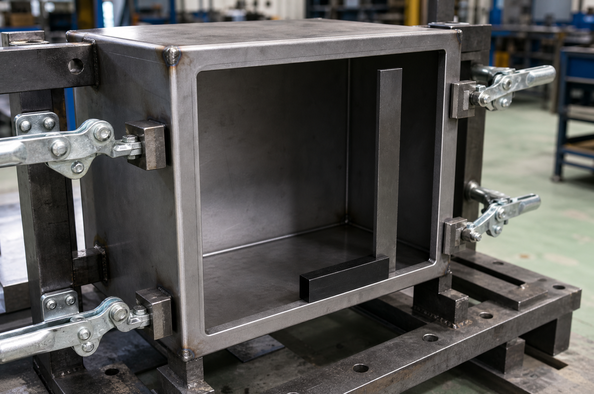
A welded enclosure body is a box made of flat panels joined at their edges, and every weld shrinks. The shrinkage pulls the corners in, which bows the frame faces, which is exactly where the gasket has to sit flat. The countermeasures are ordinary and they are all in the sequence rather than in the weld itself.
| Distortion | What it does downstream | Control |
|---|---|---|
| Corner shrinkage pulls the frame faces in | Gasket land no longer in one plane; door seals at the corners and not mid-span | Weld sequence from the middle outward, fixture holding the frame, cool in the fixture |
| Body out of square | Door binds at one corner; the mounting plate no longer aligns with the opening | Diagonal check on the frame opening before the door is fitted, and again after coating |
| Panel oil-canning between welds | Visible waviness on a coated face; a flatness complaint that cannot be corrected after coating | Weld pitch, and a shallow swage or stiffener where the panel is large and thin |
| Over-grinding a dressed weld | Local thinning, a heat-affected patch that coats differently, and a visible shadow under raking light | Dressing standard agreed at review, and a check on the ground area before coating |
| Weld on the seal land | Land is neither flat nor continuous; grinding makes it worse | Design the corner so the weld is off the land |
Squareness is worth one paragraph on its own, because it is the dimension that is argued about most and specified least. "Square" on a control enclosure drawing usually means the frame opening is a rectangle; the shop check is the two diagonals, and the acceptance is that they match to within a stated value. The number itself is a design decision — it should be tight enough that the door closes on its gasket without a fight and loose enough that a welded body can be made repeatably — and it belongs on the drawing rather than in a conversation after the first article.
Coating comes after all of this, and it does not correct any of it. A body that is 1 mm out of square is still 1 mm out of square with 80 µm of powder on it, plus a film thickness that varies with how the part hung on the rack. That is why the dimensional report is issued on the coated part: the numbers the customer assembles to are the numbers after finishing.
Materials and Finish, Chosen by Environment
Four substrates cover nearly every control enclosure enquiry, and the choice is usually made on the installation environment and the customer's finish standard rather than on strength.
| Substrate | Where it is the right answer | What to watch in fabrication |
|---|---|---|
| Cold-rolled steel, 1.0–2.0 mm | Indoor control enclosures, machine-mounted cabinets, painted finish in a standard color | Cut edges and uncoated interior faces are the corrosion start; the coating has to reach inside |
| Hot-dip galvanized steel | Outdoor and damp locations where a painted finish is not required or is applied over the zinc | The zinc at a cut edge is not restored by the coil coating; edges need a zinc-rich touch-up or a design that keeps them out of the weather |
| 304 stainless | Food, beverage, washdown and pharma-adjacent equipment where the enclosure is cleaned | Welds need finishing and passivation; the seal land should be formed, not welded |
| 316 / 316L stainless | Chloride exposure, coastal and marine installation, aggressive cleaning chemistry | Same as 304 plus a higher material cost that is worth confirming against the actual chloride level |
| Aluminum | Weight-sensitive machine-mounted enclosures, anodized or painted finish, and where EMI gasketing is planned | Welding distorts more and changes the alloy temper; a bonded or riveted construction is often better |
Finish on a control enclosure is specified by color and gloss because those are the visible attributes, and the attributes that determine service life are the substrate preparation and the film build on the faces that see the environment. Powder coating is the default for painted enclosures; galvanized steel left unpainted is common outdoors; stainless is usually supplied with a brushed or passivated finish and no coating at all. The one finish decision that belongs to this page rather than to a coating page is the masking: the bonding pads, the thread, and any gasket land that must stay bare.
Material selection at this level is covered in more detail on our materials page, and the corrosion side of stainless in particular on the stainless steel enclosure page — the grade question there is about chlorides and weld condition rather than about enclosure structure. Coating routes and finish options sit on the surface finishing page.
Inspection: What Is Measured on an Empty Enclosure
An enclosure inspection report is usually a single page, and its value depends entirely on whether the dimensions listed are the ones the customer assembles to. The list below is the one we work to, with the instrument that produces each number.
| Check | Instrument | What a pass establishes |
|---|---|---|
| Overall dimensions | Tape or height gauge on a surface plate | The envelope the customer allocates space for |
| Clear opening | Calipers across the frame return, both directions | The aperture the plate and the components have to pass through |
| Frame squareness | Diagonal comparison on the opening | That the door will not bind and the plate will land on its standoffs |
| Cutout position and size | Height gauge and calipers from the stated datums, or CMM for a dense pattern | That the components land where the layout says |
| Hole pitch | Calipers hole-to-hole, or a checked template | That a multi-hole device (HMI, disconnect) fits without elongating |
| Door gap and flushness | Feeler gauge at eight points | Even compression of the gasket, and a door that sits in one plane |
| Gasket land flatness | Straightedge and feeler, before coating | That the seal has a continuous flat surface to compress against |
| Coating thickness | Magnetic or eddy-current gauge, five points per face | The film build actually applied, not the nominal |
| Masked pads and threads | Visual against the drawing, thread gauge | That the bond path and the fastening are not coated over |
| Weld and edge condition | Visual, under raking light | No spatter, no sharp aperture edges, no over-ground patches |
Two notes on reading that table. First, the gasket land is checked before coating because that is when it can still be corrected; everything else is checked after, because that is the state the customer receives. Second, a dimensional pass says nothing about sealing. The IP or NEMA performance of an enclosure is established by testing the complete assembly with its gasket, hardware and cable entries, and a report full of green dimensions is not that test. The quality system and the certificates we hold are listed on the quality certifications page. Fabricators who blur the two are usually selling confidence rather than parts.
Where a project needs more than a dimensional report, the usual additions are a first article inspection on every drawing dimension for the first part of a revision, material certificates for the coil or sheet, a coating thickness record per batch, and a photograph set of masked pads and gland plates. All four are documents about the empty enclosure, and all four are things we can issue without implying an electrical approval.
What the Drawing Has to Carry
Control enclosure drawings arrive in every state from a full 3D model with a component layout to a photograph of an existing cabinet with "make it like this". The list below is what makes the difference between a quote and a guess.
| Item | What to state | What goes wrong without it |
|---|---|---|
| Enclosure type and envelope | Wall-mount, floor-standing or junction box; external and internal dimensions | Internal depth is assumed from the external size and a component no longer fits |
| Substrate and gauge | Material, thickness, and whether the door uses the same gauge as the body | Door stiffness and hinge load are decided by a number nobody chose |
| Structure | Welded or folded body, corner detail, frame return width | The clear opening differs from the drawing's assumption and the plate will not come out |
| Door and hinge | Single or double door, hinge side, hinge type, open angle, latch type and count | Hinge hardware is bought after the door is punched, and the holes do not match |
| Cutout schedule | Every aperture with size, position from stated datums, corner radii, and the component it takes | The hole is right and in the wrong place, or the corner radius will not take the bezel gasket |
| Mounting plate | Plate size, thickness, hole pattern, standoff height, and the removal method | The plate fits empty and cannot be removed populated |
| Cable entry | Gland plate outline, hole sizes and positions, gland make or thread engagement, sealing method | The gland bottoms out, or the plate has no seal of its own |
| Bonding | Pad positions and sizes, stud or thread, and whether the door strap is supplied | Pads are missing on the second batch, or land on a weld |
| Finish | Color and gloss reference, internal and external faces, masked areas, substrate preparation | The interior is left bare on a washdown unit, or the mask line lands on a visible face |
| Protection target | NEMA Type or IP code, the standard it is being verified to, and who is verifying | The structure cannot plausibly pass, and the test is scheduled after production |
| Inspection | Which dimensions are reported, the sampling, and any first-article requirement | "Full inspection" is quoted and nobody agrees what was measured |
Enclosure Types and the Parts We Fabricate
The same set of operations produces every item below; what changes is the structure, the gauge, and how much of the assembly is welded. A project can be a single component — a replacement door, a mounting plate for an existing cabinet — or a coordinated set where the body, door, plate and gland plate are machined to fit each other.
Wall-Mount Control Enclosures
Single door, folded or welded body, four-point wall fixing through brackets or a rear flange. The commonest brief, and the one where the frame return and the clear opening decide whether the mounting plate is serviceable.
Floor-Standing Control Cabinets
Fabricated frame with side and rear panels, plinth or base frame, and a door that may be split. Gauge, frame section and bracing are set by the height; above roughly 1,800 mm the door stiffness and the frame squareness become the controlling dimensions, not the sheet size.
PLC and Automation Enclosures
Bodies built around a component layout: plate hole pattern for the controller and I/O, duct clearance, HMI aperture in the door, and the depth that the wiring needs behind the plate. Supplied empty, or with the plate and hardware fitted as a mechanical sub-assembly.
Doors, Front Panels and Access Panels
Replacement or new doors with the aperture pattern cut and the hinge and latch holes positioned in one setting. The most common aftermarket request we see is a door for an enclosure whose original supplier has stopped supporting it.
Mounting Plates and Subpanels
Flat or formed plates with a drawing-defined hole and slot pattern, standoff positions, and a removal method designed against the opening. Galvanized is the default; painted or stainless where the environment requires it.
Cable Gland Plates and Entry Panels
Removable plates with a hole schedule sized to the gland, a flat size that clears the locknut, its own sealing method against the body, and a bonding provision. Small parts, high information density, and the component most often revised late.
Junction Box and Terminal Enclosures
Compact bodies with a lid or a screwed cover, cable entries on two or four faces, and internal fixing bosses. Usually lower gauge, tighter corner radii, and more holes per square meter than anything else in the range.
Brackets, Standoffs and Interior Parts
Mounting brackets, DIN rail supports, duct clips, earth studs and interior fixings. Where a part needs a machined interface, it is turned or milled on our CNC side rather than formed, which is the practical advantage of buying sheet metal and machined parts from one supplier. The turning and milling capability behind those parts is set out under CNC machining services.
What Moves the Price
Control enclosures are quoted per unit, and the unit price is driven by a small number of decisions that are almost all visible on the drawing. Knowing which ones your design controls is the difference between a quote that can be compared and one that cannot.
| Driver | Why it costs | Where there is room to trade |
|---|---|---|
| Welded versus folded body | Welding adds fit-up, a fixture, dressing and a distortion check; a folded body with riveted or screwed corners is much faster | Fold the body where the seal land allows it; reserve welding for the corners that carry load |
| Number of apertures | Each cutout is a program step, an edge break and an inspection line; a dense pattern can double the laser time | Standardize hole sizes so one tool path serves several devices |
| Aperture tolerance class | ±0.2 mm on a formed door is routine; ±0.1 mm needs machining after forming or a dedicated fixture | Tighten only the apertures whose component actually needs it |
| Door stiffness measures | A return, a stiffener or a second latch each add a step and hardware | Choose the cheapest measure that meets the seal requirement, at drawing stage |
| Mounting plate complexity | A dense hole pattern plus standoffs plus a removal requirement is three constraints on one part | Simplify the pattern to the components that must be located precisely |
| Masking | Every masked pad is a manual operation before coating and an inspection after it | Consolidate pads; use one earth stud per panel rather than several small ones |
| Substrate | Galvanized and stainless cost more per kilogram and change the cutting and welding parameters | Specify stainless where it is cleaned or exposed, not everywhere |
| Finish scope | Coating the interior as well as the exterior roughly doubles the coated area | Leave the interior bare where the environment allows it and the standard permits |
| Inspection scope | A dimensional report plus a first article is labour, not machine time | Move to sampling after the first article is approved |
| Volume and repeatability | Setup is amortized across the batch; a repeat order on the same drawing is significantly cheaper than the first | Order the annual quantity in call-offs against one setup |
What to Send With an Enclosure Enquiry
An enclosure enquiry that arrives with a drawing and a component layout can be quoted in a day. One that arrives with a photograph and a size can be quoted too, but the quote will carry assumptions, and assumptions are what first articles are for.
| Send this | Why it changes the quote or the part |
|---|---|
| Dimensioned 2D drawing plus the 3D model | The drawing controls inspection; the model catches interference that the drawing does not show |
| Substrate, gauge, and whether the door shares the gauge | Sets stiffness, hinge load, weld parameters and material cost |
| Cutout schedule with datums | Aperture size, position, corner radius, edge break and the component each aperture serves |
| Cutout drawings from the component makers | The aperture tolerance and the bezel gasket style come from them, not from the enclosure design |
| Component layout, even if preliminary | Decides plate size, duct clearance, door stiffening and whether the plate can be removed |
| Mounting plate removal requirement | Whether the plate must come out populated, and in which direction |
| Gland plate schedule and gland make | Thread engagement, flat size, pitch and plate thickness |
| Bonding pad positions and stud specification | Masking, hardware and the bare pad outline |
| Finish: color, gloss, faces coated, masked areas | Coating scope is one of the largest variable costs on a cabinet |
| Protection target and how it will be verified | NEMA Type or IP code, the standard edition, and who runs the test |
| Quantity: prototype, pilot, annual | Setup amortization and whether a fixture is worth building |
| Inspection and documentation scope | Dimensional report, first article, material certificate, coating record |
If some of that is not decided yet, send what exists and say which items are open. A quote that names its assumptions is more useful than one that quietly makes them, and it is much easier to compare against a second supplier.
Frequently Asked Questions
What is control panel enclosure fabrication?
Do you build complete control panels, or only the enclosure?
Can you fabricate an enclosure from our drawings, or from an existing sample?
What tolerance can you hold on cutouts and hole patterns?
Can you supply NEMA 4X or IP66 rated enclosures?
What is the difference between UL 508A and UL 50E?
How do you keep the door sealing after powder coating?
Can you mask grounding pads and threaded holes?
Can the mounting plate be removed after the panel is wired?
Which materials and gauges do you use for control enclosures?
Can you match an existing enclosure or supply a replacement door?
What documentation comes with a batch?
What information do you need to quote an enclosure?
Send the Enclosure Drawing and the Component Layout
The review that decides the price happens before the sheet is nested. Send the dimensioned drawing with the cutout schedule and its datums, the component layout, the plate and gland plate requirements, the bonding provisions, the finish scope and the protection target. You get a response on structure, gauge, aperture tolerances, masking and inspection scope — with anything that cannot be built as drawn raised at that point rather than at first article.
Request an Enclosure QuoteSTEP, IGES, DWG, DXF or PDF drawings · single components or coordinated enclosure sets
Need a plastic enclosure instead? PVC and molded electrical boxes →