5-Axis CNC Machining for Precision Surgical Instrument Components
A surgical instrument component is not accepted because it measures to the drawing. It is accepted because the jaw closes symmetrically, the pivot turns without play, and nothing sharp or loose is left inside a bore. Those are relationships between surfaces, and on a part 40 mm long the reliable way to hold a relationship is to cut the surfaces that belong together without letting go of the part. That, and not the word "complex", is the case for five axes here.
At a Glance
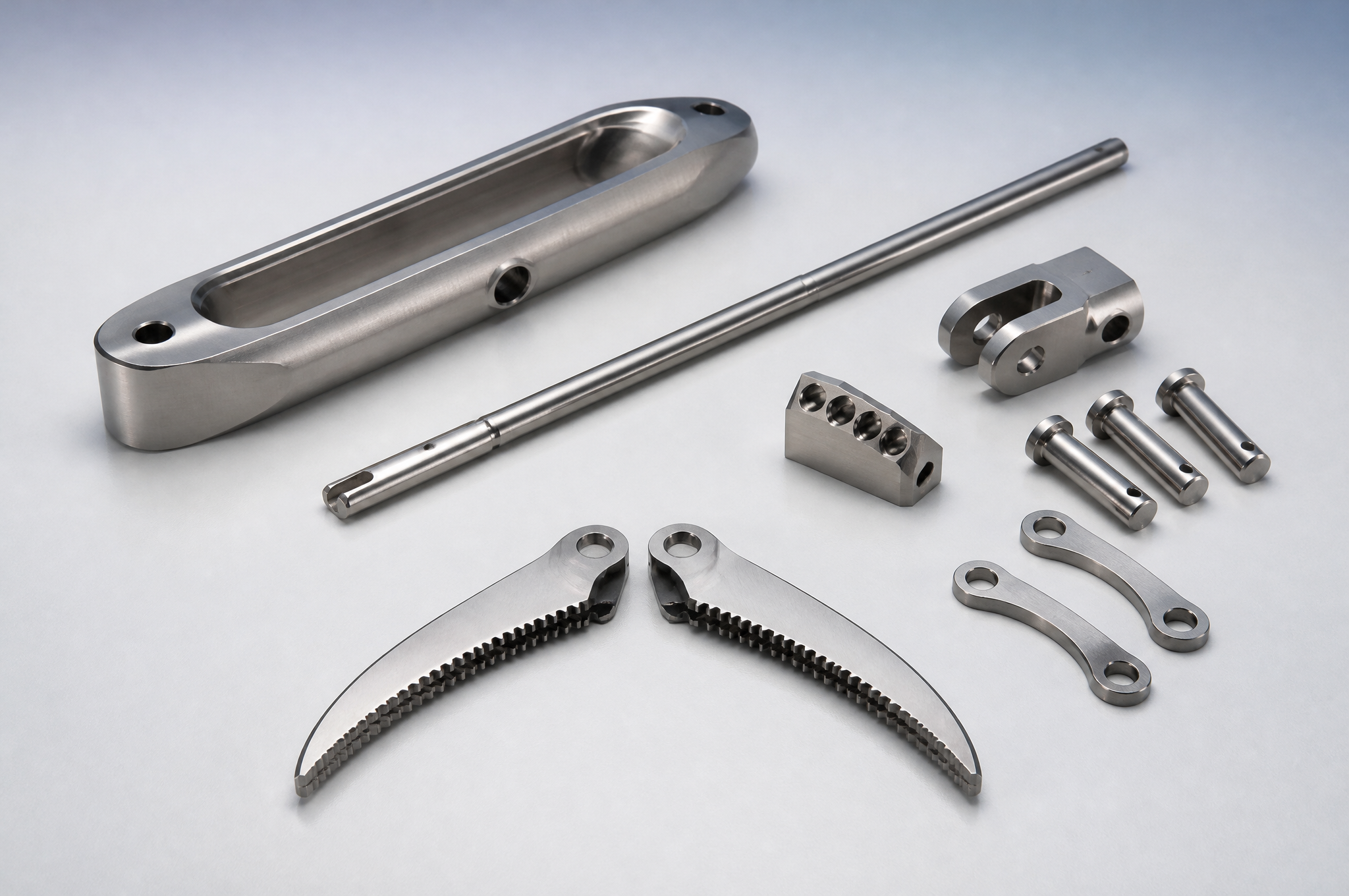
5-axis CNC machining for surgical instrument parts is used where a component's function depends on several surfaces cut from different directions — the two halves of a jaw, a slot and its coaxial pivot holes, an end effector with an angled relief — and where releasing the part between those cuts would let the datum move. Typical components are jaw halves and grasper parts, pivot and clevis components, slender shafts and drive couplings, minimally invasive distal components, drill and cutting guides, and instrument housings. Components are machined to customer 2D drawings or 3D models in 316L stainless, 17-4PH, Ti-6Al-4V, 6061 aluminum or PEEK, with deburring, passivation or electropolishing, CMM and gauge inspection, first article inspection and material traceability agreed per order. The method — turning, 3+2 indexing, simultaneous 5-axis or another route — is chosen from the geometry and the tolerance, not from the marketing. Goldcattle manufactures components; design validation, sterilization validation and market approval remain with the finished-device manufacturer.
Scope: Component Manufacturer, Not Finished-Device Manufacturer
This page is about metal and plastic components machined to a drawing. It is not a claim to design, validate, sterilize, package or place a surgical instrument on the market, and the difference is worth stating at the top rather than in a footnote, because it decides which drawings we can accept and which questions we will hand back.
| Item | Component supplier (our scope) | Finished-device manufacturer |
|---|---|---|
| Geometry | Manufacture to the customer's drawing; raise anything that cannot be cut as drawn | Owns the design input, the tolerances and the drawing revision |
| Material | Machine the specified grade and condition; supply the mill certificate and heat or lot traceability | Chooses the grade for the application and defines the material specification |
| Fit and function | Hold the relationships the drawing defines; gauge the pivot, the bore, the position | Validates that the assembled instrument performs as intended |
| Cleanliness | Remove chips, coolant and burrs to an agreed limit; handle and pack to protect the surface | Validates the reprocessing instructions, cleaning efficacy and bioburden |
| Sterility | Not in scope | Sterilization validation, sterile barrier and shelf life |
| Market access | Not in scope | Risk management, technical file, conformity assessment, registration |
The practical consequence: we will quote a jaw half, a clevis, a shaft with a slot and two cross holes, a guide block with angled bores. We will not quote "a grasper" as a finished instrument, and we will not sign a statement that a component is fit for clinical use. A supplier who offers both is describing two different businesses.
The Six Component Families, and the Failure Each One Is Judged On
The list below is not a catalogue. It is a statement of what we will quote, grouped by what goes wrong when the part is wrong — because that is what the drawing has to control, and what the inspection has to prove.
| Family | Typical form | What decides acceptance | The failure that gets noticed |
|---|---|---|---|
| Jaw halves and grasper components | Thin curved blades, 0.8–2 mm section, with a serrated or smooth gripping face and a pivot hole | Closed-jaw gap along the length; symmetry between the halves; serration pitch and depth; pivot hole position relative to the gripping face | A jaw that meets at the tip and gaps at the base, or grips harder on one side |
| Pivot, clevis and joint components | Slotted blocks, links, yokes, pins and bushings | Coaxiality of the two pivot holes; bore size and roundness; clearance to the actual pin; burr at the bore breakout | Play or stiffness in the hinge; a joint that binds after passivation; a pin that will not enter |
| Slender shafts and drive components | 2–6 mm shafts, 80–200 mm long, with flats, slots, cross holes and a drive end | Straightness; runout about the functional axis; concentricity of the drive end to the shaft; slot and flat position | Whip or bind when rotated; a shaft that will not pass its cannula; a drive that engages only in one orientation |
| Minimally invasive distal components | Small links, angled jaws, tiny pins and clevises, 3–15 mm | Profile and feature position; edge condition; the articulation plane; burr on the inside of the joint | A tip that articulates out of plane, or a joint that is stiff at one end of its travel |
| Guides and cutting blocks | Blocks and plates with parallel or angled bores, slots and a locating face | Bore size; angular position of each bore; spacing between bores; flatness of the locating face | A drill that walks, or a fastener that enters at the wrong angle |
| Handles and instrument housings | Bodies with internal cavities, actuator interfaces and a grip contour | Cavity depth and position; interface position relative to the cavity; surface condition in the grip zone; burr at every edge | An actuator that will not seat; a cavity that traps soil; a sharp edge at the thumb rest |
Two families on that list are usually confused with others. A guide block is not a bracket with holes in it: its value is the angular relationship between bores, and that relationship is only as good as the single setup it was cut in. A handle is not a cosmetic shell: the cavity is the datum for everything that moves inside it, so the drawing has to locate the mechanism from the cavity, not from the outside contour.
The Jaw Is Defined by a Gap, Not by a Dimension
Ask what a jaw has to do and the answer is not "be 45 mm long and ±0.05". It is "close on tissue evenly along its length". That is a gap between two surfaces, measured at three points, and it is created by two parts that were machined separately — which is where the trouble starts.
There are two ways to make a matched jaw pair, and they fail differently.
| Route | How symmetry is created | What can still go wrong |
|---|---|---|
| Machine both halves in the closed position, from one block or one fixture, then separate | By the cut itself: the two mating faces are the same surface divided, so the gap is whatever the cutter left | Separation stress and burr at the parting line; the halves must be numbered and kept as a pair |
| Machine each half to its own drawing | By two datums and the sum of their errors — doubled, because there are two parts | Every error at the pivot is multiplied by the lever to the tip; the pair may need matching or fettling at assembly |
| Machine each half and match at assembly | By hand or by selective assembly | Not repeatable in a batch; the matched set is not interchangeable with the next one |
The arithmetic is the part most drawings leave out. A jaw is a lever with the pivot near one end. If the pivot sits 8 mm from the datum face and the tip is 40 mm from it, an error of 0.02 mm at the pivot geometry becomes 0.10 mm at the tip. A drawing that calls a 0.10 mm maximum jaw gap and a ±0.05 mm general tolerance has, in effect, specified a ±0.02 mm tolerance at the pivot without saying so — and the first article will show it.
The gripping face is the second decision. Serrations are cut with a small ball-nose or dovetail cutter, and the cutter has a radius, so a drawing that shows a sharp-crested tooth with a sharp root is asking for something a rotating tool cannot leave behind. In practice the tooth becomes a radiused crest with a fillet at the root — which grips differently, and which cleans differently, because the fillet is either a place where soil sits or a place where it flows off, depending on how generous it is. If the tooth form matters functionally, it should be dimensioned as a radius, not as a sharp profile.
On very small jaws the same problem appears in reverse: the tooth pitch gets finer, the cutter gets smaller, and the depth of cut per pass falls until the cycle time is dominated by a tool that is effectively polishing the surface. That is a design-for-manufacture conversation, not a machining complaint, and it is worth having before the drawing is released rather than after the first quote.
The Pivot Is a System, Not a Hole
A pivot is a bore, a pin, and the two faces that carry the load. Change any one of them and the fit changes, so a bore tolerance quoted on its own is only half a specification.
The first thing to fix is what the drawing means by the pin. In most instruments the pivot pin is a purchased part — a ground dowel, a shouldered pin, a rivet that is set after assembly — and the fit is a decision about clearance, not about the bore alone. A 2 mm bore with a 0.02 mm diametral clearance feels like nothing on the bench and like a loose jaw at the tip, again because of the lever. Where the design needs a joint with no perceptible play, the usual answers are a controlled interference with a press-fit pin, a bushing in a softer body, or a pin that is formed over after assembly — and each of those changes what the drawing has to call out.
| Decision | Option | Consequence on the part |
|---|---|---|
| Hole through a slot | Bore or ream from one side in one setup | Coaxial by construction; the joint runs true |
| Hole through a slot | Ream each ear separately | Guaranteed step at the joint; needs line-boring, a mandrel or a matched reamer to recover |
| Pin fit | Clearance fit | Simple, replaceable, and a source of play at the jaw |
| Pin fit | Interference / press fit | No play; the bore tolerance and the pin tolerance become one system, and assembly can distort a thin ear |
| Pin fit | Bushing | Serviceable and tunable; adds a part and an assembly step |
| Bore edge | Break the edge with a defined chamfer | Gives a brush or a borescope access; removes the burr site at the same time |
| Bore edge | Leave as machined | A raised rim at breakout, invisible after assembly, and a wear particle in service |
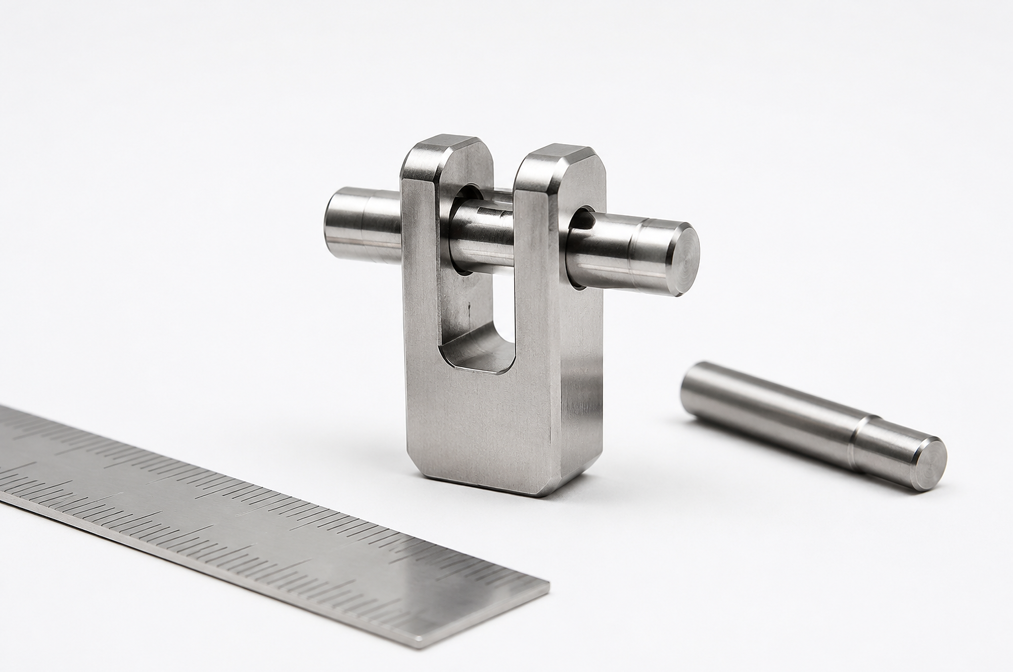
The second thing to fix is the burr at the breakout. When a cross hole is drilled into a bore, or a slot is milled through to an internal cavity, the cutter exits and pushes a ring of metal ahead of it. That ring ends up inside the assembly, where it is invisible, where it wears against a moving pin, and where it is the first thing a cleaning validation will find. Deburring it after the fact is a matter of access: a 1 mm cross hole into a 6 mm bore, 10 mm deep, cannot be reached with a hand tool.
So the deburring method is chosen at the drawing stage, not at the end of the route. Abrasive flow reaches internal intersections uniformly but is a batch process with its own validation. A back-chamfer tool works on a through hole and not on a blind one. An electrochemical or thermal process goes everywhere and needs a controlled chamber. Hand work reaches what a hand can reach, which is exactly the set of features that were never the problem.
Thin Walls and Slender Shafts: the Part Moves Before the Tool Does
Instrument components are small and lightly built, which makes them flexible on the machine as well as in the hand. Two shapes cause most of the trouble: the slender shaft, and the thin wall.
A 4 mm shaft 130 mm long has a length-to-diameter ratio of about 32. Turned unsupported, the radial cutting force pushes it away from the tool, so the middle comes out measurably larger than the ends and the surface carries a chatter pattern. Supporting it with a tailstock or a steady rest fixes the deflection and introduces a second problem: the support becomes part of the datum, and any error in the center hole or the steady's alignment is now built into the part. The center holes are the reference for everything afterwards; damage one and every measurement that follows describes a different axis.
| Symptom | Real cause | What actually controls it |
|---|---|---|
| Middle of the shaft oversize | Deflection under cutting force | Support, reduced depth of cut, a finishing pass at low radial engagement |
| Runout high, straightness fine | The centers are offset; the shaft is straight about a bent axis | Re-cut the centers; measure straightness and runout separately, because they are different claims |
| Shaft bends after milling the flats | Residual stress released by removing section | Sequence: rough, relieve, finish; or specify a stress-relieved stock |
| Thin wall closes after clamping | Clamping force applied to an unsupported wall | Soft jaws bored to the part, low-pressure clamping, or support from behind |
| Wall thickness varies around the part | The wall deflected during the cut and sprang back | Finish the wall with the part supported, then take a light final pass |
| Part is round in the chuck, oval on the bench | Elastic recovery after release | Measure free-state, not clamped; that is the state the customer receives |
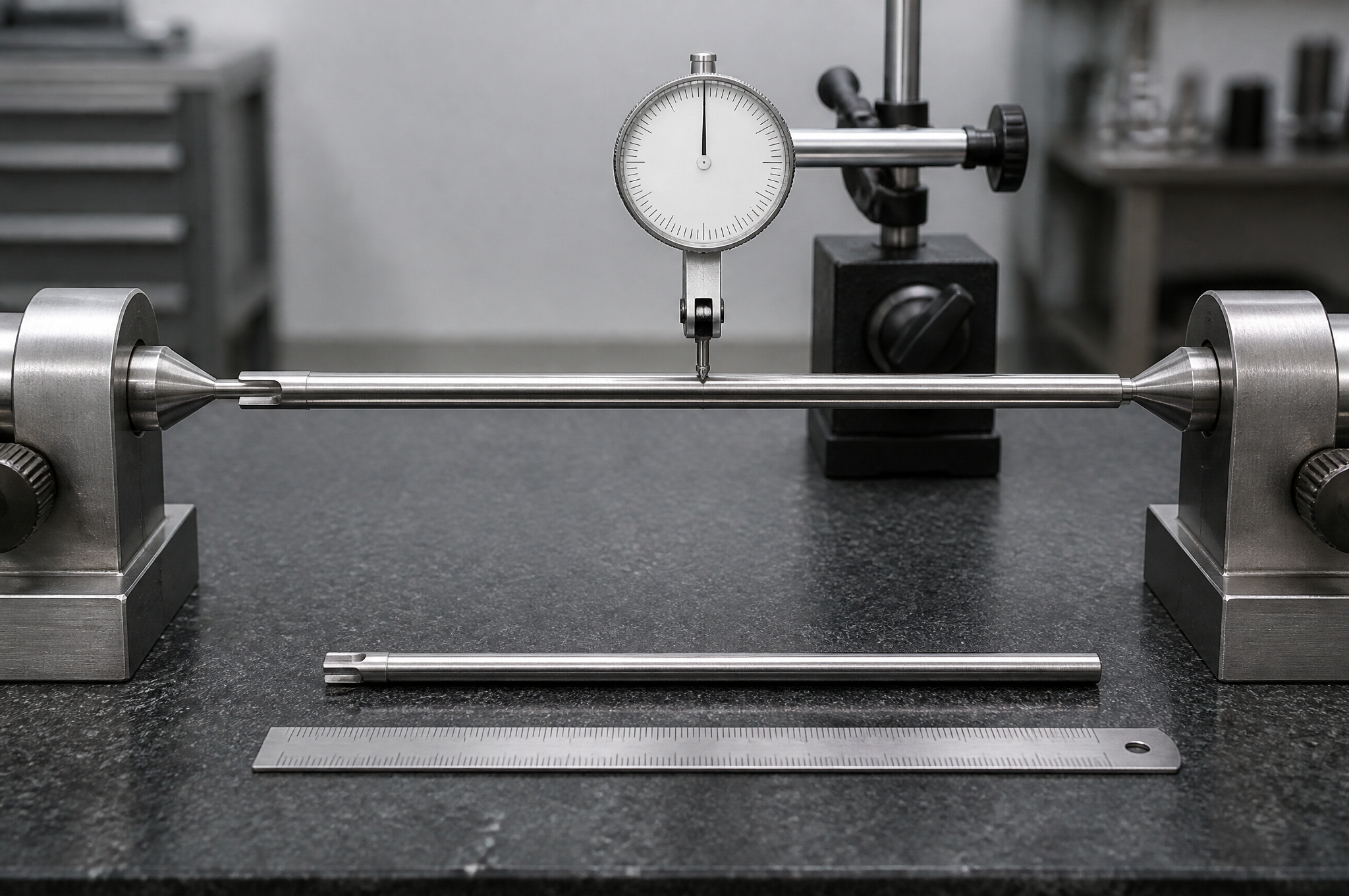
For thin walls the number that matters is not the wall thickness but the ratio of wall thickness to diameter. Below roughly 1:30 the wall behaves like a shell: it will not hold its roundness under clamping and it will not hold its position under a finishing cut. The practical answers are all workholding answers — a conforming collet, a low-melt filler, a sacrificial support web that is removed last — and none of them can be added after the part is quoted without changing the price.
Micro-Features, Tool Reach and the Temptation to Over-Tolerance
Instrument geometry tends to concentrate into small features: a 0.6 mm slot, a 0.4 mm cross hole, a 0.2 mm corner radius, a relief groove 1.2 mm wide and 3 mm deep. Each of these is a tool-access problem before it is a machining problem.
| Feature as drawn | What limits it | What to change |
|---|---|---|
| A slot 0.6 mm wide and 4 mm deep | Length-to-diameter ratio approaching 7; the cutter tapers and deflects | Reduce the depth, open the width, or accept a wider tolerance at the bottom of the slot |
| A sharp internal corner | The tool has a radius, so the corner does | Call the radius you can accept, or move the corner out of a stressed section |
| A 0.2 mm corner radius in a 4 mm deep pocket | A cutter small enough to leave it cannot reach that depth | Specify the radius at the depth, not at the smallest radius in the catalogue |
| A cross hole entering a blind cavity | No exit for the burr; no access for a deburring tool | Make the cavity a through feature, add a relief, or accept a defined burr limit and inspect it |
| A 0.01 mm tolerance on a 0.4 mm feature | No practical metrology with the required uncertainty at that size | Tolerance what can be measured; state the measurement method on the drawing |
| A thin rib standing 6 mm proud | It deflects during the cut and rings afterwards | Add a supporting web removed last, or thicken the rib root and slim the top |
The last row of that table is the one worth arguing about, because it is a rule that both sides benefit from: if a feature cannot be measured with a stated uncertainty, it should not carry a tight tolerance. A 0.01 mm callout on a 0.4 mm wide slot is not a specification — it is a number that will be signed off because nothing on the shop floor can contradict it. When a drawing does carry one, we will say so at review and propose either a different feature or a measured characteristic with a defined method.
Choosing the Process: Five Axes Are Not Automatically the Answer
Every surgical instrument component can be described by which features have to agree with which, and that description chooses the machine. The table below is the decision we actually make at review; a quote that applies five axes to a plain shaft is charging for capability the part does not use.
| Part structure | Route | Why that route | What the route cannot do |
|---|---|---|---|
| Constant-section shaft, no cross features | CNC turning, with support | Fastest metal removal per hour; the axis is the datum | Cross holes and flats need a second operation or live tooling |
| Shaft with flats, slots and cross holes | Turn-mill, one chucking | All features referenced to the turned axis without re-chucking | Limited by bar capacity and the number of live tool stations |
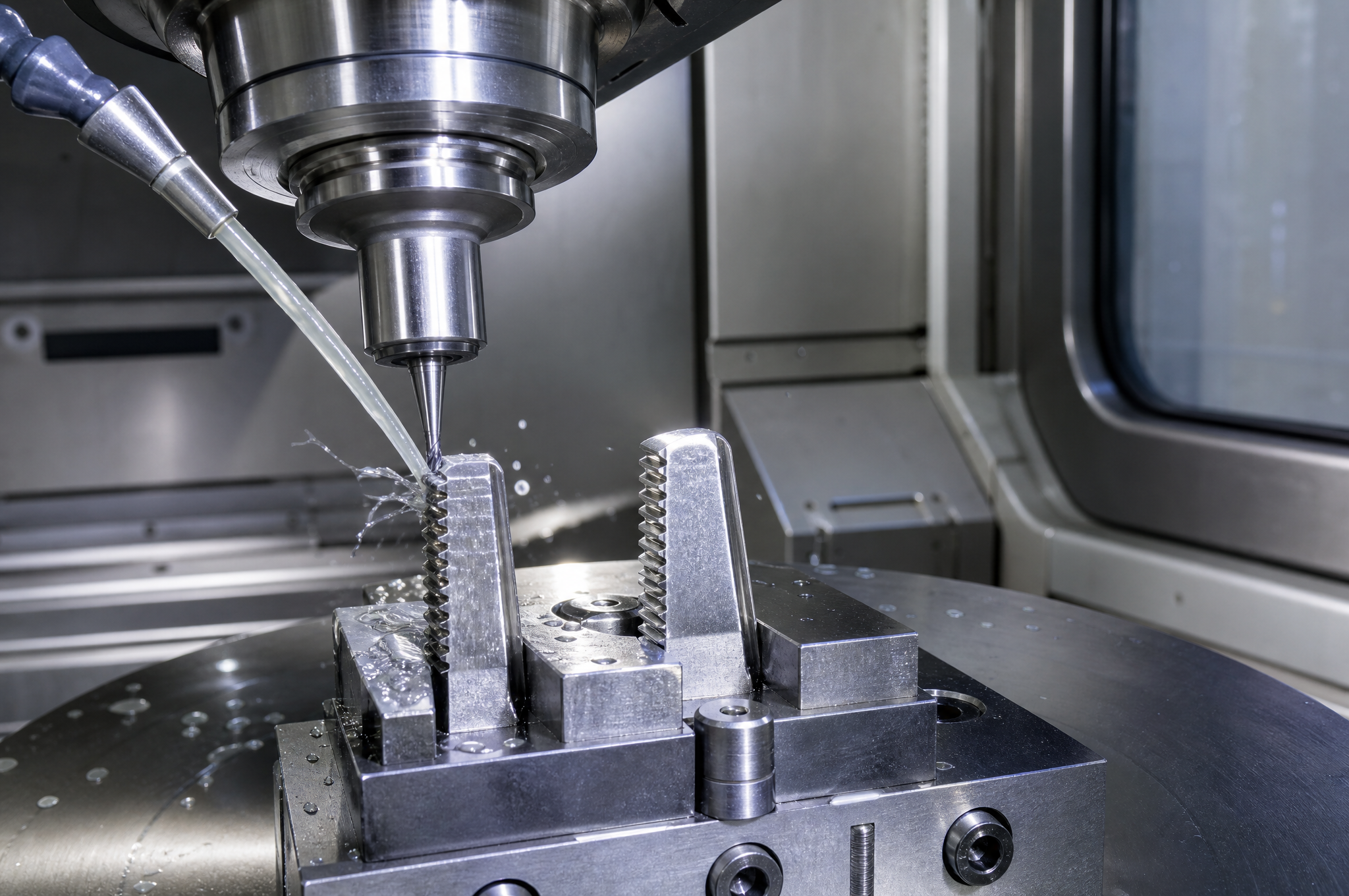
| Clevis, yoke, multi-face joint, angled pad | 3+2 indexed on a 5-axis machine | Each face is machined as a flat face from a rigid index position; position comes from one setup | Not for continuous curvature; index positions cost time |
| Curved jaw, serrated profile, end effector | Simultaneous 5-axis milling | The tool stays normal to the surface, so the profile is cut without witness lines and without re-fixturing | Slower per cubic centimeter; needs a CAM strategy built for small tools |
| Sharp internal corner, deep narrow slot, hardened section | EDM, wire or sinker, if the geometry demands it | No cutting force, so no deflection; reaches geometry a cutter cannot | Slower; recast layer and electrode cost; not every shop runs it in-house |
| Cutting edge in a hardened martensitic stainless | Grind after hardening | Hardness above what a cutter will survive | Requires hardening and hardness verification — a separate capability, not assumed |
The honest summary: three-axis work with good fixtures beats five-axis work with bad ones, and the reason to move to five axes is a specific list — features on faces that cannot be reached without re-clamping, a profile that has to be continuous across a curve, or a tolerance that is destroyed by the second setup. When none of those is true, the cheaper route is also the more accurate one.
Burrs, Cross-Holes, and What "Deburred" Actually Means
"Deburred" is not a specification. It is an intention. A 0.05 mm burr on the inside of a 2 mm bore is a wear particle waiting to happen; the same 0.05 mm burr on the outside edge of a handle is a handling annoyance. Until the drawing says which locations and what limit, the shop will remove what it can see and the customer will find what it cannot.
Three kinds of burr matter on an instrument component, and they are removed by different methods.
| Burr location | Why it matters | Method that reaches it | Method that does not |
|---|---|---|---|
| Inside a bore, at a cross-hole breakout | It sits in the bore where the pin runs; it cannot be seen after assembly; it sheds particles | Abrasive flow, electrochemical, thermal, or a back-chamfer tool if the geometry allows access | Hand tools, unless the bore is short and open at both ends |
| At the exit of a through hole | It lifts the mating face off its seat and creates a gap that traps soil | Back-chamfer, orbital deburr, brush through the hole | Anything that only touches one side |
| On a milled edge or a slot rim | It is a cutting edge in a part that touches tissue and gloves | Controlled edge break — a defined radius, not "remove sharp edges" | A polishing pass that rounds the whole face |
| At the start of a thread | It interferes with the first thread and produces a false torque reading | Chamfer before threading, or a thread-mill that leaves a clean start | Chasing with a tap after the fact |
| At an intersecting pair of milled pockets | It blocks a passage and collects chips during cleaning | Program a finishing pass along the intersection; abrasive flow for the residue | Blasting, which peens it into the corner |
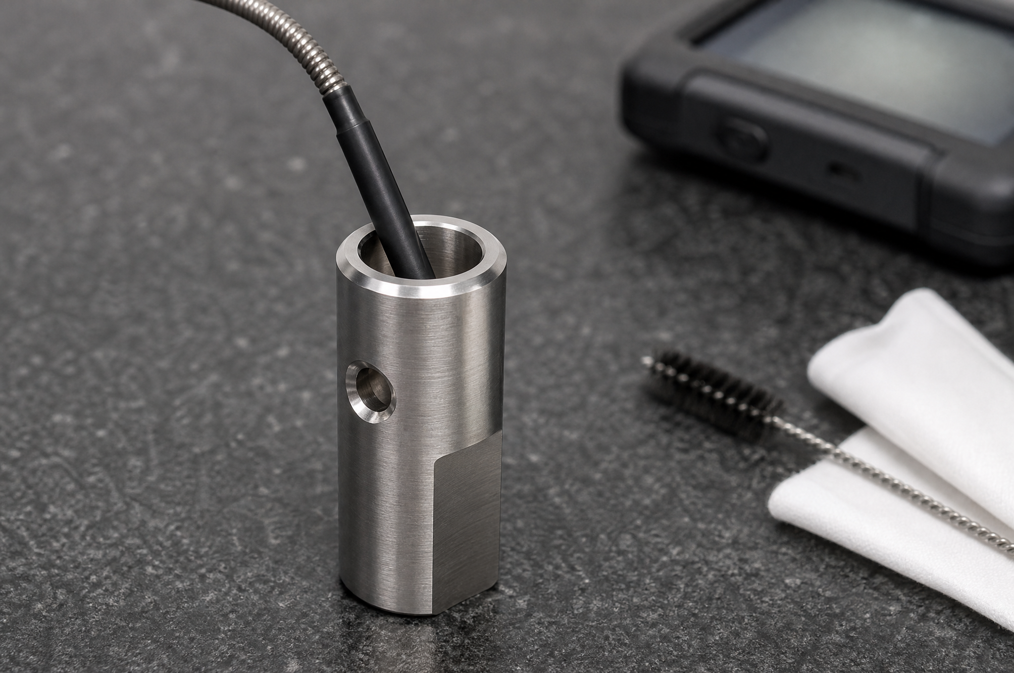
Two practical notes. First, the deburring method has to be chosen before the geometry is frozen, because access is a function of geometry — a 1 mm cross hole into a blind 6 mm bore has no route in, whatever the process. Second, the inspection of a deburred part is itself a method: a visual check at 10× finds an edge burr and misses the one inside; a borescope finds the internal one; a defined edge radius measured on a profile projector is the only version of "burr-free" that can be reported as a number.
Cleanability Is Decided in the Machining, Not in the Cleaning
A reusable instrument is cleaned, inspected and sterilized between every use, and the geometry that makes that difficult is the same geometry that traps chips and coolant during manufacture. So the cleanability question is not a regulatory formality bolted on at the end; it is a set of features that either can be flushed or cannot.
| Feature | Why it traps | Machining-side alternative |
|---|---|---|
| Blind hole at the end of a bore | Fluid enters and cannot leave; the floor is a dead end | Through hole where function allows; if not, a radiused floor and a documented flush path |
| Cross hole into a closed cavity | Two openings, one chamber, no flow path | Open the cavity to a second exit, or add a relief that lets the flow turn |
| Narrow slot with a square root | Capillary retention in the corner; a brush cannot reach the last 0.5 mm | Full-radius root, or open the slot width at the root |
| Two faces clamped together with no gap | A zero-clearance crevice that holds fluid by surface tension | Specify a relief groove or a defined standoff so the gap can be flushed |
| Pressed pin in a thin ear | A crevice line at the press fit that opens with thermal cycling | Bushing, or a pin with a defined shoulder and a relieved body |
| Serration valley with a sharp root fillet | Soil sits in the bottom of every tooth | Generous root radius; the same change that makes the tooth cuttable makes it cleanable |
The manufacturing boundary is worth being precise about, because it is easy to overclaim. We control component cleanliness: chips, coolant residue, loose particles and burr, to a limit agreed on the purchase order, with ultrasonic cleaning and handling to protect the surface. We do not validate a reprocessing instruction, demonstrate cleaning efficacy against a soil challenge, establish bioburden, or qualify a sterile barrier. Those are the finished-device manufacturer's obligations, and a supplier who implies otherwise is describing work it does not do.
What we can do is make the manufacturable version of the design obvious at review: when a cavity has no exit, when a slot root will hold a brush, when a mating face has no relief. Those are usually ten-minute changes on a drawing and expensive changes after tooling.
Materials: What the Application Asks For
The grade is not a preference; it follows from what the part does. The five below cover most instrument components we are asked to quote, and each carries a specific penalty that belongs in the conversation.
| Grade | Why it is chosen here | What to watch |
|---|---|---|
| 316L stainless | Corrosion resistance through repeated cleaning cycles; machinable; weldable; the default for instrument bodies, pivots and shafts | Gummy and work-hardening, so speeds and coolant matter; low strength, so it is a poor choice for a highly loaded pivot in a thin section |
| 17-4PH stainless | Strength in a small section, with a hardness that can be raised by aging | The condition is a heat-treatment decision: machining in the annealed state and then aging moves dimensions, so the sequence and the allowance have to be agreed before the first cut |
| Ti-6Al-4V (Grade 5) | Strength-to-weight and corrosion resistance for loaded, lightweight components | Low thermal conductivity concentrates heat at the edge; chatter and tool wear are the normal problems; the burr is stubborn and does not respond to the same deburring as stainless |
| 6061-T6 aluminum | Housings, fixtures, prototypes and non-patient-contact structures where weight and cost matter | Not for a load-bearing instrument part; an anodized layer is not a wear surface for a moving joint |
| PEEK (unfilled or carbon-filled) | Insulating, chemically resistant, low-weight parts; the grade is often specified for a reason | Machined here, not molded; residual stress and dimensional stability after machining need a stress-relief step; carbon-filled grades are abrasive on tooling |
Material verification follows what the drawing names. Where a customer's specification cites a standard for instrument stainless — ASTM F899 and ISO 7153-1 are the ones that come up — we machine to the grade and condition the drawing calls for and supply the mill certificate with heat and lot identification. What we do not do is assert that a part "meets" a standard in the abstract: a standard's applicability is defined by the product and by its own scope, and the binding requirement is always the customer's specification.
Finishing Changes the Part, and Electropolishing Changes It Most
Surface finishing is usually specified for corrosion resistance or appearance. On an instrument component it is also a dimensional operation, and one of them removes material in a way that is easy to forget until a pin will not fit.
| Process | What it does | Dimensional consequence |
|---|---|---|
| Passivation | Removes free iron from the surface and restores the passive oxide layer on stainless | None measurable; it is a chemical cleaning, not a stock removal |
| Electropolishing | Levels micro-peaks and improves the surface; brightens the part | Removes material — tens of micrometers per surface — so bores grow, edge radii grow and a fine cutting edge rounds over |
| Mechanical polishing | Cosmetic or functional surface improvement; can round edges | Local removal, least controlled at edges and at hole rims |
| Bead blasting | Uniform matte finish; hides tool marks | Peens the surface; can distort a thin section and can leave media where there is an open cavity |
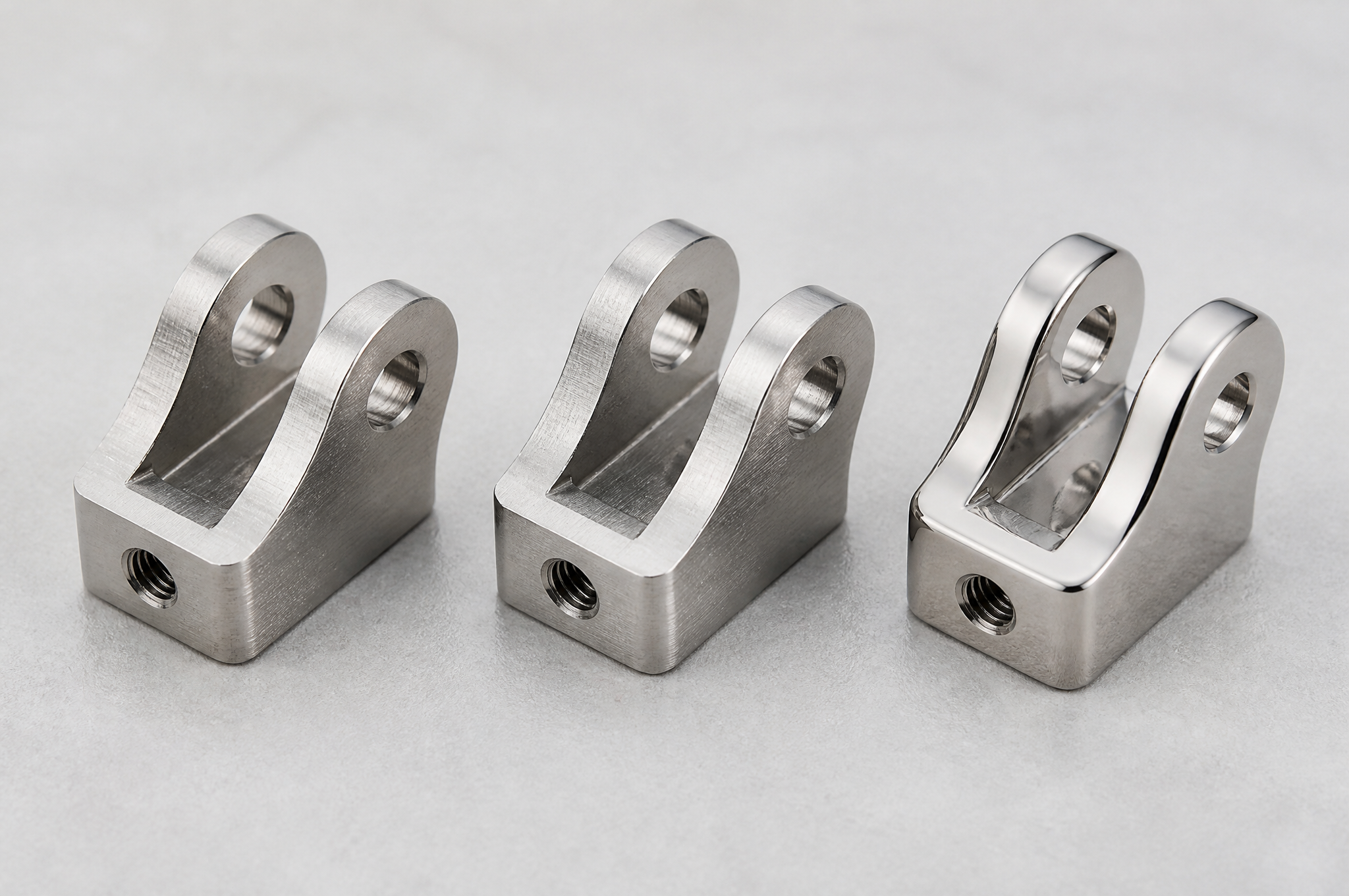
Two consequences follow. The finish belongs in the process route before the bore tolerance is fixed: a 2 mm pivot bore that is reamed to size and then electropolished comes back larger, and the play that appears at the jaw tip was designed in at the finishing step. And electropolishing is not automatically desirable: on a serrated gripping face it rounds the teeth, which is the opposite of what the tooth is for. When both a smooth exterior and a sharp tooth are needed, the answer is usually to mask, to polish before cutting the teeth, or to accept the tooth as machined and polish only the body.
The Critical-to-Quality Matrix
Most instrument drawings carry thirty dimensions and five that matter. The five are the ones that fail at assembly, and they are the ones worth naming explicitly on the drawing and on the inspection report. The table is the one we build at review, and it is the difference between a report that proves a part is the right size and a report that proves it will work.
| Characteristic | Function it decides | How it should be verified | What the number does not prove |
|---|---|---|---|
| Jaw profile and closed gap | Even contact along the gripping length | Optical profile or CMM scan of the closed pair; gap at three stations | That the tissue grip is even in use — that is a design and test question |
| Pivot bore diameter and coaxiality | Whether the joint turns freely, with play or without | Pin gauge or bore gauge; a pin through both ears for coaxiality | That the pin stays put under load; retention is a separate feature |
| Shaft concentricity and runout | Whether the instrument runs true through its cannula | Between centers with an indicator; CMM for the drive end | That the shaft will not bend in service |
| Guide bore size and angular position | Whether a drill or a screw enters where intended | Pin gauge for size; CMM or a functional gauge for angle and spacing | That the drill will not walk in bone — that is a function of the guide's face and the user |
| Mating face flatness and position | Whether two parts seat without a gap | Surface plate and indicator, or CMM | That the assembly stays seated after thermal cycling |
| Internal channel diameter and continuity | Whether the passage functions and can be flushed | Pin gauge where reachable; borescope; flow check if specified | That the channel is clean — cleanliness is verified separately |
| Edge condition | Handling safety, tissue contact, burr retention | Visual at defined magnification, plus a measured radius where a limit is given | That no burr exists anywhere on the part — "burr-free" needs a location and a limit |
| Serration pitch and depth | Grip consistency between the two jaws | Optical profile on a section, or a cast and a comparator | That the grip performs as intended on the intended tissue |
| Flat and slot position on a shaft | Drive engagement and orientation | CMM or an optical comparator against the shaft axis | That the drive will not slip under torque |
| Thread size, depth and class | Whether the fastener seats and holds torque | Thread plug or ring gauge; depth with a depth gauge | That the thread will survive repeated assembly in a soft alloy |
Two habits make that matrix work. Every characteristic gets a datum, stated in the same units as the drawing, and every characteristic gets a method, because a number without a method becomes a negotiation at first article. Where a characteristic cannot be measured on the finished part — a bore inside a closed body, for example — it belongs in the process record with an in-process check, not in a final report that will quietly be filled with the drawing's nominal value.
Inspection: Measuring a Mechanism
Instrument components need three kinds of measurement: size, position, and condition. They are done with different instruments, and confusing them is how a part passes inspection and fails assembly.
| Question | Instrument | What it establishes |
|---|---|---|
| Is the bore the right size? | Pin gauge, plug gauge, bore gauge | Size and, with two axes, roundness |
| Are the features in the right place relative to each other? | CMM, from a stated datum | Position, coaxiality, perpendicularity, angular relationship |
| Does the joint actually work? | Functional gauge, or the mating part on a fixture | That the two parts assemble and move as intended |
| Is the profile right? | Optical comparator, vision system, or a CMM scan | Two-dimensional form, tooth pitch, small radii |
| Is the surface as specified? | Roughness tester on the named face | Ra on the measured area only — not on the part as a whole |
| Is anything left inside? | Borescope, magnification, flush check | Burr and residue at internal features |
The report is built from those answers, and it is worth being clear about its limit. A dimensional report proves conformance to the drawing. It does not prove that the instrument grips, cuts, articulates or cleans as intended, and no supplier's report can, because those are properties of the assembled device in use. Where a customer's technical file needs the manufacturing evidence, the package is: material certificate with heat and lot, certificate of conformance, dimensional report against the drawing's own critical characteristics, first article inspection on the first part of a revision, and process records for the special processes — passivation, electropolishing, cleaning — to the extent they are subcontracted or in-house.
How to Qualify a Surgical Instrument CNC Supplier
The questions below are the ones that separate a supplier who can make the part from a supplier who can make the part repeatably. They are written to be asked directly, and each has an answer that can be checked rather than believed.
| Question | Why it separates suppliers | What a good answer contains |
|---|---|---|
| Which components of this family have you machined before? | Family experience shows up in the fixture design, not in the brochure | A named part type, the material, and the feature that was difficult |
| How will you hold and verify the critical characteristics? | Everyone can hold an outline; the CTQ is where the risk sits | A datum, a method and an instrument for each characteristic |
| How do you control burr at internal intersections? | The most common hidden defect, and the hardest to fix later | A named process, its access limits, and how it is verified |
| Where does finishing sit in your process route? | Electropolishing changes fits; the route decides whether that was considered | A sequence with the allowance and the masked features called out |
| Can you trace the material to heat or lot? | Without it, a material question becomes an argument | Mill certificate, heat number, lot marking on the traveller |
| How are drawing revisions controlled? | Most fitment failures are a correct part made to the wrong revision | A revision on the traveller, a check at first-off, a record of the change |
| Who owns design and validation? | Clarity here prevents a supplier from implying certification it does not hold | An explicit statement that component manufacture is the scope |
| What happens when a part is out of specification? | A nonconformance process is the difference between a fix and a surprise | Containment, disposition, deviation request, corrective action |
Seven Rules That Make an Instrument Component Buildable
None of these is exotic. Each one is a decision that is cheap on a drawing and expensive after tooling, and each one comes from a part that had to be reworked.
| Rule | What it prevents | What to write on the drawing |
|---|---|---|
| 1. Put the tolerance where the lever is short | A jaw that gaps at the tip while every dimension is in tolerance | Pivot geometry at roughly one fifth of the acceptable tip gap; outline at general tolerance |
| 2. Do not tolerance what cannot be measured | A number that will be signed off because nothing can contradict it | The measured characteristic, the instrument and the uncertainty |
| 3. Leave a route to every burr | An internal burr that cannot be removed after the part is made | A through feature, a relief, or a chamfer at the breakout |
| 4. Decide the finish before the bore | A pivot that is loose because electropolishing opened it | The finish sequence, the allowance, and which surfaces are masked |
| 5. Radius the corners that flex | A crack that starts at a sharp internal corner in a thin section | A minimum internal radius at every corner in a stressed section |
| 6. Design the tooth to be cut | A serration profile that needs a tool smaller than the depth allows | A crest and root radius the cutter can leave, with pitch and depth dimensioned |
| 7. State the datum, not just the dimension | Two suppliers producing two different parts to the same drawing | A named datum face or axis, and a position tolerance from it |
The same list read backwards is the review we run on every new instrument drawing. When one of the seven is missing, the quote carries an assumption, and the assumption is written into the quotation so that the first article is not the first time anyone sees it.
Cost and Lead Time: What Moves the Number
Instrument components are rarely expensive because of material. They are expensive because of time on a small tool, time in a fixture, and time in inspection — and those three are visible on the drawing once you know where to look.
| Driver | Why it costs | What can be moved |
|---|---|---|
| Small-tool run time | A 0.5 mm cutter removes very little per minute; the cycle is dominated by the finishing pass | Open a radius, reduce a depth, or accept a broader tolerance on a non-functional face |
| Number of setups | Each re-clamp is fixture time, program time and a datum to re-establish | Consolidate features onto faces that are already being cut; consider indexed 5-axis |
| Fixtures | Small parts need dedicated workholding; it is engineering, not material | Standardise the family so one fixture covers several part numbers |
| Material | Titanium and 17-4PH cost more and cut slower; 316L is gummy rather than hard | Stay with 316L where the load allows it |
| Deburring method | Hand work is per part; abrasive flow is per batch with a setup cost | Batch size and a geometry that can be reached by a process |
| Finishing | Electropolishing is racked by surface area; masking is manual before and inspected after | Fewer masked surfaces; polish before cutting the functional face |
| Inspection | A CMM program per part number, plus the time to run it | Agree the CTQ list; a report with five characteristics is faster and more useful than one with forty |
| Quantity and revision | Programming and fixturing amortize; a new revision re-opens both | Freeze the revision and order annual volume in call-offs |
Lead time follows the same list. A first article on a new instrument component is normally dominated by fixture design, programming and the first inspection, not by cutting time; a repeat order on the same revision is a fraction of that. It is worth asking a supplier to quote both, because the ratio tells you how much of the price is one-off engineering.
What to Send for a Quote
An instrument enquiry that arrives with the drawing, the material condition and the critical characteristics can usually be quoted without a second round of questions. The list below is the one that changes either the price or the part.
| Item | What it should contain |
|---|---|
| Drawing and model | STEP, IGES, X_T, DXF, DWG or a dimensioned PDF, at a named revision |
| Component family and function | Jaw, pivot, shaft, end effector, guide or housing; what it does and what it moves against |
| Material and condition | Grade and temper, for example 316L, 17-4PH H900, Ti-6Al-4V annealed, PEEK unfilled; or "recommend" |
| Critical characteristics | The five or so dimensions and relationships that decide function, with tolerances and datums |
| Finish and sequence | Passivation, electropolishing, polishing; which surfaces are masked or must stay sharp |
| Burr and cleanliness limit | Which locations matter and what limit applies; whether ultrasonic cleaning is required |
| Evidence required | Material certificate, certificate of conformance, dimensional report, FAI, process records |
| Quantity | Prototype, pilot batch and expected annual volume, stated separately |
| Validation you will perform | The tests and approvals the finished-device manufacturer will run, so the drawing can serve them |
| Packaging and handling | Individual protection, tray or bag format, labelling and lot marking |
If the drawing is not finished, send what exists and say which characteristics are still open. A quotation that names its assumptions is easier to compare against a second supplier than one that quietly guesses, and it usually surfaces the DFM question before the fixture is made.
Frequently Asked Questions
What are 5-axis CNC surgical instrument parts?
Can you machine surgical instrument components to our drawings?
Which instrument components do you machine?
Do you need the finished instrument, or only a part drawing?
Can you hold plus or minus 0.005 mm on a surgical instrument component?
How do you control the closed gap and the alignment of a jaw pair?
How is the pivot fit controlled?
Can you machine 17-4PH and Ti-6Al-4V as well as 316L?
Does electropolishing change the dimensions of the part?
How do you deal with burrs inside cross holes?
Are you ISO 13485 certified or FDA approved?
Can you support prototypes and small batches?
Send the Drawing and the Critical Characteristics
Share the 2D drawing or 3D model at a named revision, the material and condition, the characteristics that decide function, the finish and the surfaces that must stay sharp or masked. The engineering review covers the datum, the fixture, the setup count, the burr route and where the finish will change a fit — and anything that cannot be cut or measured as drawn is raised before the quotation rather than at first article.
Request an Instrument Component QuoteSTEP, IGES, X_T, DXF, DWG or PDF · prototype, pilot batch and repeat production
See the wider medical CNC machining scope →Related Capability and Reading
Materials
316L stainless steel medical parts — what the grade does on a machine, and where it stops being the right choice.
Materials
Ti-6Al-4V CNC machining — tool wear, heat at the edge, and the burr that titanium leaves.
Process
5-axis CNC machining services — machine configuration, axis arrangement and what each one is used for.
Process
CNC surface finishing — passivation, polishing and the dimensional effect of each.
Quality
Quality and certifications — what our quality system covers and what it does not.
Parent page
Medical device CNC machined parts — the wider medical scope, including orthopedic, dental and diagnostic components.