Injection Molding · Industrial Equipment Parts
Custom Industrial Injection Molded Parts: Duty, Tooling and Program Life
Industrial molded parts rarely fail on the tolerance that was written on the drawing. They fail on a duty nobody wrote down: a sustained load that crept, a solvent that found a stressed fillet, a boss that split on the assembly line, a weld line that ran straight through the load path. This page is about the decisions on either side of the mold — what has to be specified before a tool is cut, and what has to be agreed before the program ends.
Request a duty and drawing review A drawing, a description of what the part has to survive, and an annual quantity are enough to start.
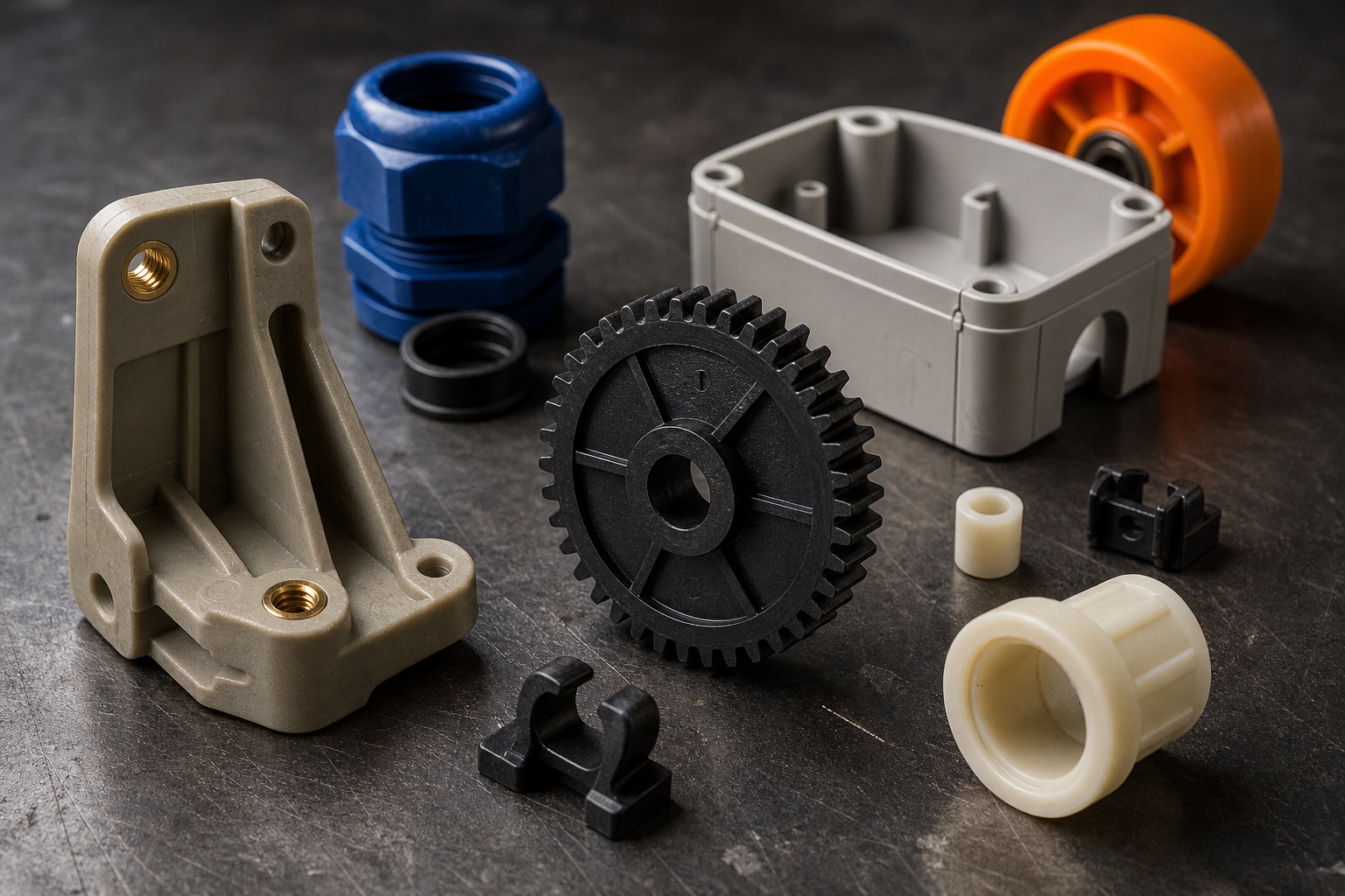
Scope of This Page
Short answer: this page covers what happens before a tool is cut and after a part is qualified: how a duty requirement becomes a material and a geometry, which tooling tier fits which demand profile, and how a molded part program is kept alive for the years it has to run.
It deliberately does not repeat the four pages that already own the middle of that chain. Each of them is more detailed on its own subject than a single chapter here could be, and repeating them is how a cluster starts competing with itself:
| If your question is | It is answered on | What this page does instead |
|---|---|---|
| What can be molded at all, and to what tolerance | Injection molding services | Assumes the part is moldable and asks whether it will survive |
| How to design the part: wall, ribs, draft, gate, cooling, vents | Injection mold making — DFM checklist | Only the three design decisions that industrial parts get wrong |
| How many cavities, which steel, what a tool costs and how long it takes | Injection mold making | Which tier to buy, and what that tier does to unit cost |
| Which process suits my part: CNC, molding or printing | Custom plastic components | Only the industrial triggers that rule molding out |
| Resin property tables and grades | Materials | Choosing by failure mechanism, not by datasheet headline |
| How an enclosure seals, and what an IP or NEMA claim proves | Industrial enclosure injection molding | Nothing — that subject is complete on its own page |
What “Industrial” Actually Changes About a Molded Part
Short answer: an industrial part is bought on continuity and consequence, not on appearance and unit price. It sits inside a machine, it is often maintained rather than replaced, it may be one of only a few hundred a year, and when it fails the machine stops. Those four facts change the material, the geometry, the tool and the contract.
A consumer part and an industrial part can look identical in a photograph and be specified in completely different ways. The difference is not the resin family and it is not the tolerance block. It is the set of conditions the part has to survive, and whether anyone wrote them down.
| Dimension | Consumer part | Industrial part | What it forces on the design |
|---|---|---|---|
| Duty | Intermittent, short events | Continuous, often for years | Sustained load becomes a design case, not an afterthought |
| Failure consequence | Replace the product | Machine down, line stopped | Redundancy in a boss or a bracket can outweigh unit cost |
| Volume | High and stable | Low and irregular, often high mix | Tooling tier and cavity count are chosen differently |
| Service life | Until the next model | Until the machine is retired, often a decade or more | Obsolete-part risk is a procurement problem, not a design problem |
| Environment | Handled, indoors, cleaned occasionally | Oil, coolant, solvents, heat, vibration, UV | Chemical and thermal exposure enter the material decision |
| Fit | New assembly, new design | Often a replacement in an existing assembly | The mating geometry is fixed before the design starts |
The last row is the one that is most often missed at quotation stage. When a molded part replaces a machined or cast one inside an assembly that was designed around metal, the interface is not negotiable: hole positions, boss heights, screw sizes and clearance envelopes are already fixed by the machine. The molded part has to be designed to the existing interface, and every one of those constraints narrows the room available for draft, wall thickness and gate position.
Part Families by the Duty They Carry, Not by Their Shape
Short answer: the useful way to group industrial molded parts is by which mechanism is most likely to end their life. A bracket and a cover can be made of the same resin but be defeated by opposite problems — the bracket by creep, the cover by impact and UV.
A shape-based catalogue tells a buyer what a supplier has made before. A duty-based table tells a buyer whether their part belongs in that group at all, which is the question they actually have. Each row below is a family, the mechanism that usually ends its life, and the one line that has to appear in the specification for the part to be quotable.
| Family | Typical duty | Usual cause of failure | What the specification must state |
|---|---|---|---|
| Mounting brackets, motor and sensor mounts | Sustained load plus vibration, often bolted | Creep under preload, then joint loosening | Static load, its duration, and the preload the screw carries |
| Equipment housings and covers | Impact, UV, occasional cleaning | Brittle fracture at a corner or a fixing | Drop or impact energy and the intended cleaning chemistry |
| Internal functional parts (cams, levers, guides) | Repeated sliding or flexing | Wear, or fatigue crack at a sharp corner | Cycle count, contact pressure and the mating surface |
| Gears, racks and drive components | Torque plus wear | Tooth wear, then tooth root fracture | Torque, speed, duty cycle and ambient temperature |
| Cable management and routing parts | Retention, occasional re-entry | Snap-fit fatigue, or stress relaxation of the clip | Number of open and close cycles and the cable bundle load |
| Fluid-adjacent parts (drip trays, shrouds, guards) | Chemical contact plus load | Environmental stress cracking at a moulded-in stress point | The exact fluid, its concentration and the temperature |
| Electrical insulating parts (standoffs, barriers) | Voltage plus heat plus contamination | Tracking across a contaminated surface, or softening | Working voltage, pollution degree, and the required flammability class |
Sustained Load: The Failure That Strength Figures Hide
Short answer: a polymer quoted at a high tensile strength can still fail under a load it carried easily for the first hour. Under sustained load it deforms continuously, and the deformation grows with time, temperature and stress. Strength is a short-event property; service is a long-event problem.
Creep is the permanent, time-dependent strain that accumulates while a constant stress is held. Three things drive it, and all three are usually present on an industrial part: the load is continuous because the machine runs, the temperature is elevated because the machine is warm, and the load is applied through a small area because the part is bolted.
The consequence that surprises buyers is that creep does not look like failure when it happens. Nothing cracks. The bracket slowly takes a set, the boss sinks a few tenths, the clamp load on the screw drains away, and the assembly that was tight at first article rattles six months later. By the time it is noticed the part has been out of specification for a long time, and the cause is attributed to the screw or the assembly rather than to the material.
| Driver | What happens | What it changes | What to put in the RFQ |
|---|---|---|---|
| Time under load | Strain accumulates; the rate slows but does not stop | The relevant material figure, which is not the short-term modulus | Expected service life, not just the load |
| Temperature | Creep rate rises steeply with temperature | Which grade within a family is usable at all | The working temperature at the part, not the ambient of the room |
| Stress level | Higher stress means faster creep and earlier onset | Wall and rib section, and how many screws carry the load | The load per fixing point, and how it is applied |
| Load path continuity | A rib that stops short of the wall carries a fraction of its nominal share | Where the ribs actually have to run | Nothing — this is a design review item |
Two design responses work better than adding material. The first is to shorten the load path: a gusset that reaches a supported wall is worth more than a thicker boss that stands in free space, because the thicker boss simply carries more load into the same unsupported corner. The second is to spread the clamp load over more fixings, which lowers the stress each boss sees and reduces the creep rate at every one of them.
Chemical Attack: Why Strength and Chemical Resistance Are Not Enough Separately
Short answer: environmental stress cracking is brittle failure caused by a chemical acting on a part that is simultaneously under load. Either one alone may be harmless. Together they can split a part in days, with no visible chemical damage and no warning before it breaks.
This is the mechanism most often mistaken for a material fault, because the resin may be listed as resistant to that chemical and the load may be well below the strength of the part. Resistance data is normally generated on unstressed specimens, and that is exactly the condition that hides ESC.
| Situation | Why it is high risk | The check |
|---|---|---|
| A moulded-in stress point such as a boss root or a sharp internal corner | Residual and service stress concentrate in the same place | Look for a radius; a sharp corner is a crack starter under load |
| Machined or reamed features on a molded part | Cutting exposes fresh surface and can leave local stress | Ask whether the feature can be moulded instead of cut |
| Parts cleaned with a solvent, or wiped with an aggressive agent | The cleaning agent was never in the material selection | Name the cleaning chemistry in the RFQ, not just the process fluid |
| Parts in contact with oil, coolant, hydraulic fluid or fuel | Prolonged contact under a preloaded screw | State the fluid, its temperature and whether contact is continuous or splash |
| Parts under a sustained preload near a fluid line | Constant stress while wetted is the textbook condition | Combine with the creep review; the two mechanisms reinforce each other |
Thermal Cycling, Vibration and the Joint That Loosens Itself
Short answer: three mechanisms that are individually mild become serious in combination: differential expansion between polymer and metal, cyclic temperature that works a joint, and vibration that converts a drained clamp load into movement. The failure shows up as a loose assembly, not a broken part.
Differential expansion. A brass insert and a glass-filled polyamide boss do not grow at the same rate. Through a temperature cycle the insert and the polymer are forced to the same displacement, so one of them is stretched and the other compressed. At the extremes the boss carries hoop stress it was never asked to carry statically, and repeated cycles work the interface. This is why an insert that survives the press-fit operation can still crack its boss a season later.
Vibration and preload. A bolted polymer joint does not loosen because the thread unwinds. It loosens because the polymer creeps under the clamp load, the preload drops, and the joint then has clearance to move. Once it moves, vibration finishes the job. The engineering response is to keep the clamp load above the working load for the whole service life, which usually means a larger bearing area under the screw head and a shorter, stiffer load path — not a higher torque at assembly.
Temperature cycling of a constrained part. A part clamped between metal components and unable to expand has its expansion converted into stress. If the part is also glass-filled and has a weld line across the constrained direction, the combination is a fatigue crack with a predictable location.
| Mechanism | Where it shows | Symptom seen by the customer | Design answer |
|---|---|---|---|
| Differential expansion | Boss around a metal insert | Hairline crack at the boss root, or insert pull-out | More wall around the insert, and a boss that is supported rather than free-standing |
| Preload loss | Bolted foot or flange | Assembly rattles; screws found at low torque | Larger bearing area, shorter load path, or a metal sleeve to carry the preload |
| Constrained expansion | Part trapped between metal plates | Crack across the part in line with the constraint | Slotted holes or clearance that allows movement, if the function permits it |
| Vibration fatigue | Any cantilevered feature | Crack at the root of the arm, not at the tip | Shorten the cantilever and add a gusset at the root |
Electrical Duty: What a Flammability Class Does and Does Not Prove
Short answer: a flammability class describes how a small specimen of a material behaves in a specified flame test. It is not a certification of the part, it does not describe tracking resistance, and it does not tell you whether the finished component is safe at your working voltage and pollution degree.
Three separate questions get collapsed into one when a buyer writes “must be flame retardant” on a drawing. They are answered by different tests and different documents, and a supplier can only respond to the ones that were actually asked for.
| Question | What answers it | What it does not tell you |
|---|---|---|
| How does the material behave in a flame? | A material flammability classification, tested on standard specimens of a stated thickness | Nothing about the finished part's geometry, wall thickness or nearby metal |
| Will a contaminated surface conduct? | Tracking resistance of the material, assessed with a comparative tracking index | Nothing about creepage and clearance distances, which are the designer's responsibility |
| Is the finished component acceptable? | Assessment of the end product against the applicable standard for its equipment type | Nothing that can be inferred from a material certificate alone |
The practical consequence for a buyer is that a request for a flame-retardant grade is not the same as a request for a compliant component. If the end product has to be assessed, the assessment constrains the material, the wall thickness at the barrier and the distances between conductive parts together, and the material has to be chosen at the same time as the geometry rather than afterwards.
Material Selection by Failure Mechanism, Not by Datasheet Headline
Short answer: choose the resin by asking which mechanism will end the part's life, then confirm the grade can carry the duty at the working temperature. The headline tensile figure on a datasheet is the least useful number for an industrial part, because it is measured in a short test at one temperature on an unstressed specimen.
| If the governing mechanism is | Families worth evaluating | What disqualifies a candidate | What to test before committing |
|---|---|---|---|
| Creep under sustained load | Glass-filled polyamides, POM, PBT, PPS | A grade whose isochronous curves at working temperature do not carry the stress | Load-hold at temperature, with the actual fixing geometry |
| Sliding wear | POM, PA with internal lubricant, PBT | A mating pair that both wear, or a grade without a defined wear partner | Wear rate against the actual mating material, not a generic steel |
| Impact at low temperature | Impact-modified PA, PC/ABS, PP depending on stiffness need | A glass-filled grade chosen for stiffness alone | Impact at the lowest service temperature, on a moulded part |
| Chemical contact under load | Depends entirely on the fluid | Any family selected from a general resistance chart | Loaded immersion or a surface-active test in the actual fluid |
| Tracking and dielectric duty | PA, PBT, PPS with a stated tracking index | A grade with no tracking data at the required class | Tracking assessment, and the creepage that the geometry allows |
| Dimensional stability across humidity | PBT, PPS, POM; polyamides need care | Unfilled PA in a tight-tolerance dry environment | Measurement after conditioning, not straight off the tool |
Two points about this table are worth stating plainly, because they are where most selection goes wrong.
The first is that the grade matters more than the family. Two polyamides can differ in glass content, impact modification, heat stabilisation and lubricant package, and those differences move the creep behaviour and the impact behaviour by more than the gap between families. A decision made at family level is a shortlist, not a selection.
The second is that polyamides change dimension as they take up moisture. A part moulded and measured dry will grow after conditioning, and the amount depends on the grade and the environment. For a part that has to fit an existing metal interface, that growth is a real dimensional allowance, and it has to be designed in rather than discovered at assembly.
Three Design Decisions That Industrial Parts Get Wrong
Short answer: the full DFM checklist is a separate subject and is covered in detail on the mold making page. Three items behave differently on industrial parts than on consumer ones, and they are the ones that turn into field failures rather than cosmetic rejects.
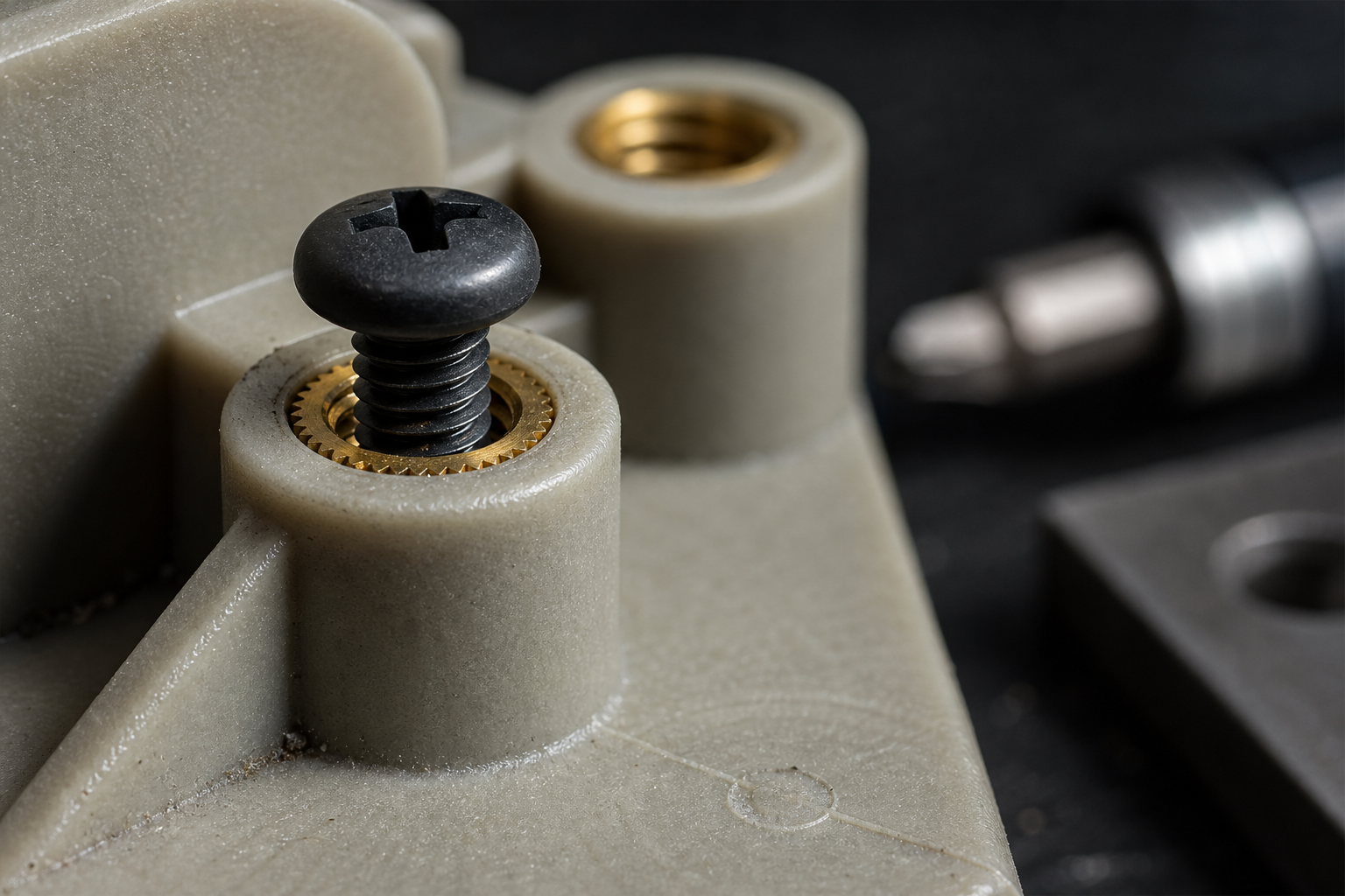
The boss that is thick where it should be thin
A boss carries load into a wall, and the wall is far thinner than the boss. Where the two meet, the section changes abruptly, and a thick boss joined to a thin wall shrinks unevenly, pulls a sink mark on the visible face and leaves a stress concentration at the junction. The standard answer is not a bigger boss: it is a boss with a wall section comparable to the adjacent wall, a generous root fillet, and a gusset that reaches a supported feature.
On a part that carries a thread-forming screw, the boss also has to survive hoop stress from the screw. The two requirements pull in opposite directions, which is why the boss diameter is a calculation rather than a default. Where an insert is used instead, the insert moves the thread load into metal, but the boss still has to have enough section to hold the insert without splitting, and enough material around it to survive the differential expansion described above.
The gate that puts a weld line in the load path
Flow that splits around a core or a boss and meets again leaves a weld line, and a weld line is weaker than the surrounding material. On a cosmetic part that is a surface issue. On an industrial part it becomes a structural issue the moment the weld line lands across the direction of the load — and it usually does, because bosses and cores sit exactly where the flow has to divide.
The fix is a gate position that puts the knit line somewhere the load is not, or a flow path that avoids the split entirely. Both are decisions made in the tool, and both are almost free at design stage and expensive after the steel is cut.
Regrind that changes the material without changing the drawing
Moulding scrap is commonly reground and blended back into production. It is a legitimate practice and it is also a material change: regrind carries a second thermal history, shorter fibre length in a glass-filled grade, and a slightly different colour. On a part where the duty is creep or impact, the proportion of regrind is a process variable that affects the property the part was chosen for.
This is why the regrind allowance belongs in the specification rather than in the processor's discretion. A stated maximum, together with a record of what went in, keeps a qualified part qualified across the life of the program.
When Injection Molding Is the Wrong Answer
Short answer: molding stops being the right process when the tool cannot be justified by the volume, when the design is still moving, when the part is too large for a practical tool, or when the geometry needs features that a two-part tool cannot release. The comparison between processes is on the components page; what follows are the industrial triggers.
| Trigger | Why molding stops working | What to evaluate instead |
|---|---|---|
| Design still changing, or a handful of parts needed for a trial machine | The tool is committed before the geometry is; every change is steel work | CNC machining or 3D printing for the trial, with the tool deferred |
| Annual quantity too low to amortise a tool over the program | The tooling contribution per part dominates the price | Machining from solid, or a lower tier of tool with a known shorter life |
| Part larger than the available platen or shot capacity | The machine becomes the constraint, not the tool | Thermoforming for large thin shells, or a fabricated and bonded assembly |
| Very deep draw with thin walls, or a large shell with uniform wall | Flow length and pressure limit the fill before the geometry is reached | Thermoforming, which forms from sheet rather than filling a cavity |
| Features that cannot be released from a two-part tool without slides on every face | Tool complexity and cost rise faster than the benefit | Machining, or a redesign that moves the features to an accessible direction |
| A single part, or a prototype where the fit is the question | Lead time on the tool exceeds the value of the answer | Machining, printed prototype, or a cast urethane part for form and fit |
Being clear about this is not a concession. A supplier who proposes machining for a twelve-part trial and molding for the production release has understood the program; a supplier who quotes a tool for twelve parts has understood the invoice.
Tooling Tiers: What Each One Buys, and Where the Break-Even Sits
Short answer: the three tiers do not differ mainly in price. They differ in how much design change they tolerate, how fast they cycle, how many cavities they carry, and how long they last. Choosing a tier is therefore a decision about design maturity and program length, not about the size of the first order.
| Prototype / trial tool | Bridge or pilot tool | Production tool | |
|---|---|---|---|
| Built for | Proving form, fit and function | Supplying a launch or a field trial | Supplying the program for its life |
| Design change tolerance | High — the tool is expected to be altered | Moderate | Low — changes are steel work |
| Cavity count | Usually one | One to a few | Set by demand and cycle economics |
| Cycle time | Not optimised | Partly optimised | Optimised, with cooling designed for it |
| Tool life | Short, and stated as short | Intermediate, stated as intermediate | Matched to the planned program volume |
| Main decision it serves | Is this the right design? | Can we supply while the production tool is built? | What is the unit cost at volume? |
The arithmetic a buyer should do before choosing
Unit price is not a single number; it is a sum of contributions that behave differently with volume. The tooling contribution is fixed and divides by the quantity. The material, cycle and secondary-operation contributions are roughly proportional and do not fall. Writing that out makes the trade-off visible:
unit price = ( tooling cost ÷ program quantity ) + material + cycle + secondary operations + margin
Only the first term responds to volume. That single fact explains most of the disagreements between a buyer comparing two quotes and a supplier explaining them: if one quote has a more expensive tool and a faster cycle, the two curves cross at some quantity, and below the crossing the cheaper tool is genuinely cheaper per part despite looking worse on the quotation.
Worked method — illustrative figures only, not a quotation
| Option A | Option B | |
|---|---|---|
| Tooling cost | 30,000 | 60,000 |
| Contribution per part, excluding tooling | 2.00 | 1.60 |
| Unit price at 5,000 parts | 8.00 | 13.60 |
| Unit price at 20,000 parts | 3.50 | 4.60 |
| Unit price at 60,000 parts | 2.50 | 2.60 |
| Unit price at 100,000 parts | 2.30 | 2.20 |
The crossover falls at exactly 75,000 parts, where both options give 2.40 per part: below that quantity Option A is cheaper, above it Option B is. The figures are invented to show the method, not to quote a price. The point is that the answer changes with the number you divide by, which is why a program quantity is a required input to a tooling decision and a first-order quantity is not.
What Actually Moves the Price of an Industrial Molded Part
Short answer: price is driven by the tool tier, the cavity count, the material, the cycle time, the amount of secondary work and the inspection burden. Of these, the two that buyers most often leave out of the request are secondary work and inspection — and those are frequently the largest variable between two otherwise comparable quotes.
| Driver | How it moves cost | Usually stated in the RFQ? |
|---|---|---|
| Inspection and documentation | A dimensional report on ten features is a different product from one on two hundred | Rarely |
| Secondary operations | Inserts, machining, welding, printing and assembly each add handling and a failure mode | Sometimes |
| Cavity count | More cavities lower cycle cost per part and raise tool cost | Sometimes |
| Material | Both the resin price and the scrap rate, which is higher for engineering grades | Usually |
| Surface and appearance | A cosmetic specification drives tool finish, polishing and the reject rate | Usually, vaguely |
| Wall thickness and cycle | Thicker walls lengthen cooling, and cooling is most of the cycle | Implicitly |
| Tool life requirement | Longer life means better steel and more maintenance planning | Rarely |
| Tolerance intent | Every tolerance tighter than the process can hold repeatably becomes sorting | Rarely |
Two of these deserve a sentence each. Appearance is the single most common source of dispute on industrial parts, because “no visible defects” is not a specification. It becomes one only when the observation distance, the lighting and the acceptable limit are written down and a physical limit sample is agreed. Without that, a supplier and a buyer can both be honest and still disagree.
Tolerance intent matters because a drawing that applies a tight tolerance globally forces the supplier to either sort parts or decline. The productive approach is to mark the few dimensions that carry function and leave the rest at a general tolerance, which is a distinction the drawing has to make explicitly rather than by implication.
Program Life: The Part of the Cost Nobody Quotes
Short answer: an industrial part program outlives its purchase orders. Over a decade a tool wears, a resin grade is discontinued, a machine is rebuilt and a buyer changes employer. The arrangements that survive those events are the ones agreed in writing at the start, and none of them appear on a quotation.
| Question | What goes wrong if it is left open | What to agree |
|---|---|---|
| Who owns the tool? | The customer assumes ownership; the supplier assumes possession | Ownership, possession and the conditions for transfer, stated in the contract |
| Who pays for maintenance and repair? | A worn tool is discovered at the worst moment, and the cost is negotiated under pressure | A maintenance basis, a wear allowance and who bears each |
| What if the resin grade is discontinued? | A qualified part quietly becomes unqualified when the grade changes | How a substitute is qualified, and who pays for the re-qualification |
| What happens at end of program? | The tool sits in a warehouse, or is scrapped without the customer's knowledge | Disposition at end of life: transfer, storage for a stated period, or destruction |
| Can a second source be added? | The customer has no route out if the supplier fails | Whether a second source is permitted, and what documentation transfers with it |
Obsolescence is the item that industrial buyers underestimate most. It is not usually the moulder's fault and it is not usually visible until it is urgent. A grade change from the resin supplier, a change in a flame-retardant package, or a shift in a glass content can all alter the part without altering the drawing, and the only safeguard is a record of what the part was qualified against plus a defined re-qualification route.
The Document Ladder: What Each Piece of Paper Actually Proves
Short answer: documents differ enormously in what they establish. A certificate of conformance proves that the supplier believes the parts conform. A first article report proves that specific features were measured on specific parts by a stated method. Treating those two as equivalent is how a supply chain ends up with confident paperwork and a failing assembly.
| Document | What it establishes | What it does not establish |
|---|---|---|
| Certificate of conformance | That the supplier asserts the parts meet the purchase order | Nothing measured, nothing sampled, nothing recorded |
| Material certificate with grade and batch | What resin went into the parts, traceable to a batch | Nothing about the dimensions or the process conditions |
| First article inspection report | That every drawing feature was measured on samples from the first production run, by a stated method | Nothing about later parts, and nothing about capability |
| Dimensional report on selected features | That the critical features were measured on a stated sample | Nothing about the features that were left out |
| Process monitoring record | That specified parameters stayed within a band during the run | Nothing directly about part dimensions — it supports the inference, it is not the proof |
| Capability study on a critical dimension | How the process varies against the tolerance, over time and cavities | Nothing about the dimensions not studied, and nothing about assembly behaviour |
The practical rule is to ask for the document that matches the risk. A cosmetic cover needs a colour and appearance agreement and little dimensional evidence. A bracket that carries a machine's weight needs a first article report with the load-path features in it, and a capability study on the two dimensions that decide whether it fits. A part that isolates mains voltage needs the material and tracking evidence, and the geometry that provides the distances, together.
What is not useful is a blanket request for the heaviest documentation set on every part. It raises the price of the parts that do not need it, and it trains the supplier to produce paperwork rather than evidence.
What to Send With an RFQ
Short answer: send the drawing, the duty, the quantity and the appearance requirement. Those four are enough for an engineering review and a tooling recommendation. The rest sharpens the price but should not block the start.
| Priority | Input | Why it changes the answer |
|---|---|---|
| Essential | 3D model and 2D drawing with the current revision | Everything downstream depends on the revision being the right one |
| Essential | What the part has to survive: load, duration, temperature, fluids, cycles | This is what selects the resin and the wall, not the shape |
| Essential | Annual quantity and the first order quantity, stated separately | The two together decide the tooling tier and the cavity count |
| Essential | The interface: what it bolts to, and which dimensions are fixed by that | Separates functional dimensions from free ones |
| Important | Resin requirement, or the performance requirement if the grade is open | An open grade is often cheaper and sometimes better |
| Important | Appearance requirement, with a limit sample or a written standard | Prevents the most common post-delivery dispute |
| Important | Inspection and documentation requirements | Can be a larger cost difference than the tool |
| Useful | Secondary operations and assembly expected | Changes handling, fixturing and the failure modes to control |
| Useful | Program life and any second-source intention | Drives tool life, documentation retention and tool ownership terms |
| Useful | Target date, and whether a trial quantity is needed first | May make a bridge tool or a machined trial the right first step |
Where to Go Next
This page stops at the edge of its own subject. Each of the pages below carries the detail that would otherwise be repeated here badly.
Machine range, materials, DFM, workflow, secondary operations and quality assurance.
DFM checklist, cavity count, steel selection, tool life, T0 to T2 trials, cost and ownership.
CNC machining versus injection molding versus 3D printing, and which part belongs where.
Resin and metal grades, with the selection criteria buyers apply in the EU and US.
Sealing geometry, ingress protection, and what an IP or NEMA claim can and cannot prove.
The management system and the documentation that can be supplied with a shipment.
Frequently Asked Questions
When is injection molding the right process for industrial plastic parts?
When the part geometry is stable, the annual demand justifies a tool, and the duty is within what a thermoplastic can carry. Parts that are still changing, needed in single figures, or larger than a practical tool should be evaluated as CNC machining, 3D printing or thermoforming first.
What information is needed to quote custom industrial injection molded components?
A 3D model and a 2D drawing with the critical dimensions, the resin or the performance requirement, the colour and surface requirement, the annual and first-order quantity, the operating environment, and any inspection or documentation the end customer requires.
Which engineering plastic should I choose for an industrial part exposed to oil, chemicals or elevated temperatures?
Match the resin to the mechanism that will attack it rather than to a family name. Oil and hydrocarbon exposure, sustained elevated temperature and specific chemical contact each rule out different materials, and the grade within a family matters as much as the family.
How does annual volume change the cost per molded part?
Tooling is a fixed cost spread across the program, so doubling the annual volume halves the tooling contribution per part. Material, cycle time and secondary operations do not fall with it, so the curve flattens and never reaches zero.
Should I use prototype tooling or production tooling for my industrial component?
Prototype tooling buys speed and low commitment while the design can still move. Production tooling buys cycle time, cavity count and tool life. The decision depends on how much the design will still change and how long the program will run, not on the first order quantity alone.
What quality documents should I request from a custom injection molding supplier?
Ask for the documents the part function needs: a first article report against the drawing, dimensional results from a stated method, material certificates carrying grade and batch, and process records where the part is safety related. A certificate of conformance states that the supplier believes the parts conform; it does not measure anything.
Who owns the injection mold, and how are tooling maintenance and storage handled?
Ownership, storage and transfer should be written into the contract before the tool is cut. Agree who holds the tool, who pays for maintenance, what happens at the end of the program, and on what terms the tool can be transferred to another molder.
Why do molded industrial parts crack at a threaded boss?
Usually the molding, not the screw. A boss that is too thick at its base, has no gusset, or sits in a weld line concentrates stress, and a thread-forming screw adds hoop stress on top. A metal insert moves the load into the insert, but only if the boss wall has enough section to hold it.
What is environmental stress cracking?
It is failure of a plastic that is under load while in contact with a chemical it would tolerate without load. Both the stress and the chemical are necessary, which is why a part that passes a simple immersion test can still crack in service.
Can a machined or cast metal part be replaced by a molded plastic part?
Sometimes, and the governing limits are stiffness and creep rather than strength. A metal part usually fails the substitution on stiffness first, because the modulus is an order of magnitude lower, and on creep second, because the plastic keeps deforming under a load that the metal carried elastically.
Have an industrial part that has to survive its machine?
Send the drawing, a description of the duty, and the annual quantity. The review covers whether molding is the right process, which tooling tier fits the demand, where the stress is likely to concentrate, and which dimensions actually carry function.
Request an industrial parts quote
A drawing and a duty description are enough to start. Missing details can be filled in during the engineering review.
Prepared by the engineering team at Xiamen Goldcattle Plastic & Metal Products Co., Ltd. This page describes selection and procurement method; it does not publish tolerances, temperature ranges or savings figures that would only be valid for a specific part, resin grade and test condition. Where a figure is needed, it is measured on the part in question.
Scope note: material property data, mold design and process capability are covered on the linked pages rather than restated here, so that each page remains the single authority for its own subject.