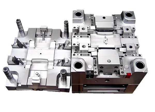
Injection Molding · Industrial Equipment
Industrial Enclosure Injection Molding: Protection, Interfaces and Production
An industrial enclosure is not a box with a lid. It is the interface between the equipment inside it and the plant around it — dust, washdown, oil, sunlight, vibration and the maintenance technician who opens it twice a year. This page is about specifying that interface so it survives, and about what can honestly be claimed once it does.
Request an engineering review Drawings, environment and volume are enough to start.
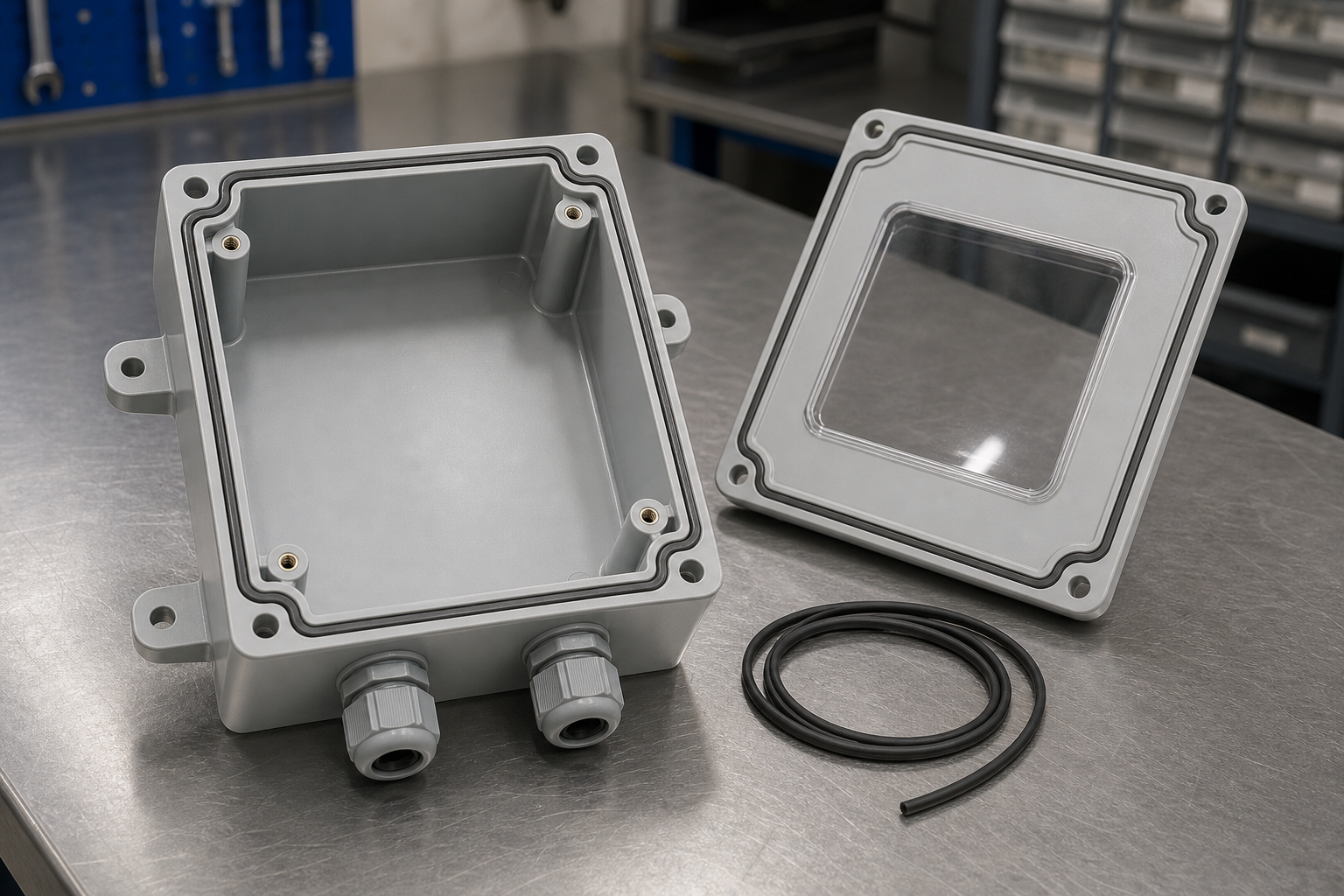
Scope of This Page, and How It Divides From Ours on Electronics Enclosures
Short answer: this page covers the industrial side of enclosure design — the operating environment, the mechanical interface to plant and machine, sealing architecture, and production supply. It deliberately does not restate PCB layout, connector placement, EMI/RFI shielding or thermal paths, which are covered on the electronics enclosure page.
The split is not cosmetic. Measured on the live pages, the electronics enclosure page runs to roughly 5,900 words across 36 headings and deals with boards, shielding, gaskets and thermal design. Across that entire page the terms DIN rail, junction box, control cabinet, NEMA, IEC 60529, vibration, outdoor, pump, instrument, wall mount and flange appear zero times. That is not a criticism of that page; it simply has a different subject. An enclosure that protects a circuit board inside a handheld device and one that protects a drive controller bolted to a wall in a washdown area share a moulding process and almost nothing else in their requirement set.
So the boundary on this page is drawn at the equipment boundary: what the enclosure has to survive outside, and what it has to hold together inside. If your question is which resin suits a sealed handheld electronics housing, or how a connector cut-out affects EMI continuity, the electronics page answers it. If your question is why the lid of a wall-mounted control box leaks after two years in a plant, this page is the right one.
The Environment Writes the Specification
Short answer: in industrial work the enclosure requirement is set by what the plant does to the box, not by what the box contains. Seven exposures account for most field failures, and each one pushes a different design decision.
This is the reason a generic enclosure drawing tends to fail in service. It was drawn from the equipment outward — board dimensions, connector positions, cable exit — and the environment was treated as a note on the drawing rather than an input to it. The exposures below are worth fixing in writing before the tool is cut, because each one changes geometry, not just material.
| Exposure | What it attacks | Design decision it forces |
|---|---|---|
| Dust and particulate | Gasket seating faces, fine ingress past cable entries | Continuous groove, no interrupted flange at corners, sealed gland interface |
| Water: spray, washdown, standing | Lid joint, screw counterbores, low-point pooling | Groove below the joint line, drain path, screw bosses outside the seal |
| Oil, coolant and hydraulic fluid | Many elastomers swell; some resins stress-crack | Gasket compound chosen for the fluid, resin checked for chemical compatibility |
| UV and weathering | Colour shift, chalking, embrittlement at thin sections | Weather-stable grade or coating; avoid very thin exposed walls |
| Temperature cycling | Differential expansion between lid, body and gasket | Gasket compression allowance, fastener spacing, material pair selection |
| Vibration and impact | Boss cracking, snap-fit release, lid fretting | Boss root support, screw rather than snap on structural joints, rib placement |
| Maintenance access | Reopened joints, lost screws, damaged gasket on reassembly | Captive fasteners, gasket retained in groove, keyed lid, tool access clearance |
Two of those rows are the ones buyers usually leave out, and they are the expensive ones. Temperature cycling is slow and shows up as a leak after a season rather than at first article. Maintenance access is not a manufacturing property at all, yet it decides whether the enclosure still seals after the first service visit — a captured gasket that stays in its groove through reassembly is worth more in the field than a slightly better compression ratio.
A note on how this page uses numbers: it describes what has to be measured and decided, and avoids quoting universal percentages, tonnages or cycle times. Those belong to a specific tool and a specific resin, and a figure lifted from another project is not a specification.
Enclosure Types and What Each One Constrains
Short answer: the enclosure category tells you almost nothing about difficulty; the interface attached to it does. A plain junction box is an easy moulding and a hostile service environment. A sensor housing is small, but its window, gland and threaded insert all compete for the same few square centimetres.
What follows is how each common industrial category tends to fail, which is more useful at quotation stage than a list of applications. Each row names the feature that usually decides the design.
| Category | Governing interface | Where it usually goes wrong |
|---|---|---|
| Control and terminal boxes | DIN rail seating, terminal access, lid flatness | Rail seat distorts when the lid screws are tightened; terminals no longer clip cleanly |
| Junction and connection boxes | Cable entries, gland threads, cover seal | Glands overtightened into a thin wall; flange bows between screws and lifts the seal |
| Sensor and instrument housings | Window, connector, threaded insert | Window frame sinks; insert pulls out under torque because the boss wall is too thin |
| Pump and fluid-system covers | Chemical exposure, clamping load, machined face | Resin stress-cracks at a sharp internal corner in contact with the fluid |
| Machine interface housings | Mounting pattern, vibration, service access | Mounting bosses crack at the root; snap-fits release under sustained vibration |
| Outdoor and remote monitoring | UV, thermal cycling, condensation | Seal works when new, weeps after a year of day-night cycling and pressure change |
Two of these deserve a warning because they cannot be designed out at the moulding stage. A DIN-rail seat that distorts when the lid is tightened is a stiffness problem, not a tolerance problem: the fix is usually a thicker or better-supported rail platform, because a tighter tolerance on a flexible platform just moves the distortion around. Condensation in an outdoor enclosure is a pressure-equalisation problem: a sealed box that breathes through its gasket will draw moisture in, and a proper breather or drain is part of the enclosure design rather than an accessory added later.
The Protection Claim Ladder: Three Different Statements
Short answer: "IP65" can mean three quite different things, and a buyer is entitled to know which one they are being offered. The moulding can support sealing; a sample assembly can pass a test; a finished product can hold a certification. These are not interchangeable, and conflating them is the most common piece of overstatement in this product category.
1. Sealing-capable design
A continuous gasket groove, a flat flange, controlled screw spacing and a seal that stays located. This is a drawing property. It can be reviewed, measured and argued about — and it is what a moulder is actually responsible for.
2. Tested assembly
A specific build — this gasket, these glands, this torque — tested to a named standard and reported. The result belongs to that build, not to the moulding, and it lapses if the gasket supplier or the torque changes.
3. Certified product
A finished product carrying a certification from a recognised body, in the configuration and application it was certified for. This is held by the product owner, and a moulder cannot confer it by moulding well.
The practical consequence is that a request for quotation should state which of the three is wanted. If it is the third, the buyer already owns most of the work: the assembly, the gasket specification, the test house and the declaration. If it is the first, the moulder can quote it today. Asking for the third and expecting it in a moulding price is where projects stall.
Two standards that are not synonyms. IEC 60529 defines the IP code — the two digits describing protection against solid objects and against water. NEMA enclosure types come from a different system and are not a lookup table against IP: NEMA Type 4X, for example, adds corrosion resistance and an external icing condition that the IP code does not address at all. A page or a quotation that swaps one for the other without saying so is telling you something about its author, not about the enclosure.
There is a related trap with flame retardancy. A UL 94 classification is a result on a plastic test specimen at a stated thickness. It says something real and useful about the material; it does not certify the enclosure, and it does not certify the equipment inside it. The honest way to write the requirement is grade, plus thickness, plus the standard — not "V-0 housing".
Sealing Architecture: Where the Water Actually Gets In
Short answer: water almost never enters through the gasket material. It enters where the flange stops being flat — between screws, at corners, at counterbores, and at the cable entry. Sealing is a stiffness and clamping problem before it is an elastomer problem.
The section below is the part of an industrial enclosure that decides whether the rating survives contact with a real plant. Four features do most of the work: the groove holds the seal against reassembly, the flange carries compression between fasteners, the screw bosses sit outside the sealed volume, and the cable entry has enough wall to be tightened into.
Schematic of the sealing joint, not a production drawing. The groove keeps the seal located through reassembly; the screw boss deliberately sits outside the sealed volume so a leaking counterbore cannot become a leak into the enclosure.
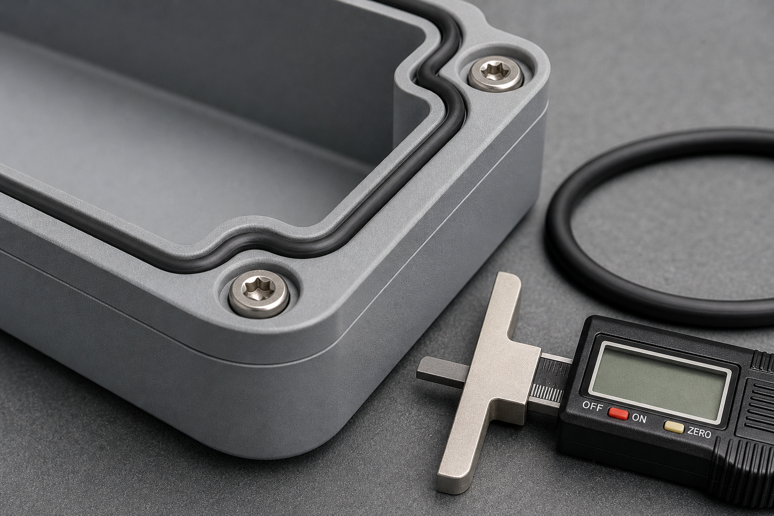
The groove holds the seal in place through lid removal and refitting, and the screw bosses sit outside it. Both details are decided in the tool, not on the assembly line.
Three geometry rules follow from that section, and they are worth stating because they are frequently broken. Groove, not flat face. A seal sitting on a flat face relies on the assembler to place it correctly every time; a groove holds it through lid removal and refitting. Fasteners outside the seal. A screw hole that passes through the sealed volume is a leak path that no gasket can close, so the bolt circle belongs outside the groove. Support between screws. Flange stiffness, not screw count, controls lift; adding screws to a flexible flange adds assembly time and can worsen distortion by clamping a wavy face harder.
Cable entries deserve their own line because they are the most common field leak. A gland seals on its thread and on the cable jacket, and both depend on a wall thick enough and flat enough to take the tightening torque without dishing. A gland mounted on a curved or thin surface seals when new and weeps after the first thermal cycle. Where a vent or breather is needed for pressure equalisation, it should be placed where it cannot be submerged and where its membrane is not exposed to direct washdown — a breather in the wrong place turns a sealed enclosure into a pump.
Material by Exposure, Not by Name
Short answer: the material list is the least useful part of most enclosure pages, because two grades of the same polymer can differ more in UV stability, impact at low temperature or chemical resistance than two different polymers do. What matters is the exposure, then the grade, then the data sheet.
The table below is a shortlist of directions, not a compatibility guarantee. Every row ends in the same requirement: a named grade, with the property that matters to your exposure confirmed on its data sheet.
| Direction | Where it is usually considered | What decides it |
|---|---|---|
| ABS | Indoor control and instrument housings | Surface quality and cost against impact and service temperature |
| PC | Higher impact duty, windows and covers | Impact and clarity against chemical resistance and moulding temperature |
| PC/ABS | Housings needing toughness with a good finish | The specific grade's flame target and flow behaviour |
| PA and PA-GF | Structural brackets, mounting parts | Moisture uptake and fibre orientation, which move dimensions after moulding |
| PBT | Electrical and structural components | Thermal performance and dimensional stability at the stated grade |
| PP | Chemical exposure and light-weight covers | Stiffness, creep and low-temperature impact |
| ASA and weather-resistant grades | Outdoor and UV-exposed housings | Colour retention and impact after ageing, confirmed by the grade data |
| Flame-retardant grades | Electrical housings with a stated classification | Classification at your wall thickness, not at the supplier's test thickness |
Two rows cause most of the avoidable rework. Glass-filled polyamide is often specified for stiffness without accounting for the fact that its dimensions continue to move as it takes up moisture, which is a poor match for a sealing flange. And a flame-retardant grade is often chosen for its classification without checking that the classification was established at a thickness the design does not use — a thin wall can fall outside the tested range entirely.
Material data, grade comparisons and the wider resin set are collected on the materials page. What is specific to industrial enclosures is that the gasket compound has to be chosen at the same time as the resin: a seal that is correct for water may swell in oil, and a resin that resists a fluid may be attacked by the plasticiser in the gasket.
The Interfaces That Cause Most Failures
Short answer: generic enclosure DFM advice covers walls, ribs, draft and parting lines. Those matter, and they are covered on the electronics enclosure page. What fails in industrial service is more specific: the rail platform, the boss root, the gland wall, the window frame and the snap-fit under vibration.
The distinction is worth making because the fixes are different. A wall-thickness rule is a drawing note; an interface fix is usually a local geometry change that has to be agreed before the steel is cut.
| Interface | How it fails | What actually changes the outcome |
|---|---|---|
| DIN rail platform | Seat distorts under lid clamping; terminals no longer engage | Platform stiffness and support, not a tighter tolerance |
| Screw boss root | Crack at the root under torque or vibration | Root fillet and gusset, boss wall thickness, screw type |
| Threaded insert boss | Insert pulls out or splits the boss | Boss wall around the insert and the melting method, verified by torque test |
| Cable entry wall | Gland dishes the wall and the thread seal weeps | Local thickening and a flat land around the entry |
| Window or display frame | Sink marks and a frame that will not seat flat | Frame section and gate position, not polishing after the fact |
| Snap-fit in a vibrating machine | Creep and release after sustained load | Screw or captive fastening on structural joints; snap-fits for covers only |
| Mounting lug | Lug cracks when the bolt is tightened against a non-flat surface | Lug thickness and a spot-faced seating area |
One pattern runs through the table: almost every industrial interface failure is a stiffness failure being mistaken for a tolerance failure. When a lid lifts between screws, the instinct is to tighten the tolerance on the flange; the effective fix is usually to stiffen it. When a rail seat distorts, the instinct is to hold the seat dimension more tightly; the seat is simply flexing. Getting this distinction right early is the difference between a tool that works and a tool that is cut twice.
Tooling Route and Volume Logic
Short answer: injection moulding earns its place when the enclosure carries integrated features and the volume justifies a tool. At low volume, or where the part is essentially a folded box, sheet metal or a machined prototype is usually the better answer — and saying so early saves a project.
The honest comparison for an industrial enclosure is not "injection versus everything else" but "which route holds the interfaces the design needs at this quantity". A gasket groove, a moulded boss, a rail seat and a window frame are all cheap to mould and expensive to fabricate any other way. Against that, sheet metal is stiffer per unit thickness, tolerates modification without a new tool, and is cheaper below the volume where tooling amortises.
| Route | Fits when | Costs you |
|---|---|---|
| Injection moulding | Integrated features, repeatable assembly, sustained volume | Tool lead time and a one-time tool cost; changes after cut are expensive |
| Sheet metal | Simple geometry, low volume, stiffness priority, likely revisions | No integrated bosses or grooves; sealing needs separate gasketing |
| CNC machining | Prototypes and low-volume functional parts, tight tolerances | Unit cost and material waste; slow to scale |
| Additive | Form and fit checks before tooling | Surface, strength and cost per part at any real volume |
Where injection is right, two tooling decisions dominate the economics: cavitation and tool construction. Cavitation is set by annual volume against the risk of tooling a family that later changes; a single or two-cavity tool is often the correct choice for an industrial enclosure that will be revised, even where the volume would support more cavities. Tool construction is set by expected life and by how much the part will be changed. The mould-making side of this is described on injection mold making, and the wider process comparison is on injection molding services.
Validation and Documents: What Each One Proves
Short answer: most quality arguments in this category come from a document being read as proof of more than it contains. A first-article report proves the part matches the drawing; it does not prove the enclosure is watertight, and it never proves a rating.
The table sets out what each document actually establishes. It is worth agreeing this list before the tool is cut, because some items have to be planned into the trial rather than added afterwards.
| Document | What it establishes | What it does not |
|---|---|---|
| First-article dimensional report | The moulded part matches the drawing at the measured points | Sealing performance, or behaviour after thermal cycling |
| Resin certificate | Which grade was used, traceable to a batch | That the grade suits your chemical or UV exposure |
| Trial record | The settings the parts were moulded at, and the runner and cycle data observed | That the process window is wide enough for production — that is a capability study |
| Flange flatness measurement | Whether the sealing face is flat enough to compress a gasket evenly | That the assembled unit seals under pressure or spray |
| Insert torque test | Whether the insert and boss survive the specified torque | Behaviour after thermal cycling or vibration |
| Appearance record | The surface condition under a stated lighting and viewing condition | Colour match against a physical standard, unless that is included |
| Third-party ingress test | That a specific assembly passed a named test | That another build, gasket batch or cable configuration will pass |
The flange flatness measurement is the one most often skipped and most often decisive. A sealing flange that is flat when it leaves the tool can bow after ejection or after annealing, and the distortion is usually not visible until the lid is bolted down. Measuring it on the part, not on the drawing, is what converts a gasket specification into something that works on the assembly line. Where a formal capability study is needed, it belongs with the dimensional work on quality certifications.
Production Supply and Change Control
Short answer: an industrial enclosure is bought for years, not for one order. What protects the buyer is not a capability statement but a change-control arrangement: who may change the resin, the gasket, the tool and the process, and what happens when they do.
Four changes silently invalidate an earlier validation, and all four are common in a long programme. A resin grade change, even within the same family, can move shrinkage and sealing-flange flatness. A gasket supplier change alters compression set. A tool repair that welds or inserts steel changes local cooling. And a process change made to improve cycle time alters the frozen-in stress that decides whether the flange stays flat.
The arrangement that works is unglamorous: a fixed drawing revision, an agreed deviation process, a first-article on any change to resin or tool, and a record of which gasket and which torque the validated build used. Buyers who ask for this at the quotation stage usually get it, because it costs a supplier very little to agree to and a great deal to be held to later. Buyers who ask after a leak in the field get a discussion about whose fault it is.
Frequently Asked Questions
What types of industrial enclosures can be injection molded?
Control and junction boxes, sensor and instrument housings, pump and fluid-system covers, machine interface housings and outdoor monitoring enclosures are all routinely moulded. The constraint is not the category but the geometry: wall section, sealing flange, mounting interfaces and the number of features that must hold tolerance together.
Which materials are suitable for industrial plastic enclosures?
ABS, PC, PC/ABS, PA and PA-GF, PBT, PP and weather-resistant grades such as ASA are all candidates, but suitability is decided by the exposure rather than the material family. Two grades of the same polymer can differ more in UV stability or chemical resistance than two different polymers, so a grade and a data sheet are required.
Can injection-molded enclosures be designed for IP-rated sealing?
Yes, the moulding can provide a continuous gasket groove, a flat sealing flange, controlled screw spacing and sealed cable entries. What the moulding cannot do on its own is establish an IP rating: the gasket, fasteners, cable glands, assembly torque and the complete enclosure must be tested as an assembly.
What information is required to quote a custom industrial enclosure?
A 3D model, a dimensioned 2D drawing, the resin grade and any flame requirement, the equipment and environment it protects, annual and first-order quantities, mounting and cable-entry requirements, target protection class and the critical dimensions that must hold. Missing items can be resolved during review, but the environment and the volume cannot.
How do wall thickness, ribs and bosses affect enclosure quality?
They set three things at once: whether the part fills, where it sinks or warps, and whether the sealing flange stays flat after ejection. Bosses and ribs are usually thinner than the nominal wall so they cool faster than the material around them; that difference, not the nominal thickness alone, drives sink marks and flange distortion.
Can flame-retardant materials be used for industrial enclosures?
Flame-retardant grades can be evaluated against the classification and wall thickness you specify. A material classification such as UL 94 applies to a test specimen of a stated thickness; it does not certify the finished enclosure or the equipment inside it, so the requirement should be written as a grade plus a thickness plus the applicable standard.
How are gaskets, cable entries and mounting features designed?
The gasket groove is sized for a specific cord or moulded seal at a stated compression, the flange is kept flat between screws, and screw spacing is set so the flange cannot lift between fasteners. Cable entries are placed where a gland can be tightened and where the cable will not load the seal, and mounting features are kept out of the sealing zone.
When is injection molding more suitable than sheet metal fabrication?
Injection moulding becomes the better route when the enclosure carries integrated features such as bosses, ribs, snap-fits, gasket grooves and mounting lugs, when quantities justify tooling, and when repeatable assembly matters more than sheet-metal stiffness. Sheet metal remains stronger per unit thickness and cheaper at low volume.
What inspection documents can be provided for custom enclosures?
First-article dimensional reports against the drawing, material certificates for the resin grade used, records of the trial settings, sealing-flange flatness measurements and appearance records under the agreed lighting condition. Documents beyond that, such as third-party ingress testing, are project-specific and should be agreed before the tool is cut.
How do tooling costs and production volumes affect the unit price?
The tool is a one-time cost that is spread over the order quantity, while the unit price follows cycle time, cavitation, resin price, reject rate and secondary operations such as insert fitting or assembly. That is why the same enclosure can be cheaper per part at higher cavitation only once volume is sufficient to keep the tool loaded.
Where to Go Next
| If your question is | Go to |
|---|---|
| Board layout, connector placement, EMI/RFI, thermal paths | Electronics enclosure injection molding |
| General plastic housing capability and materials | Custom plastic components |
| Mould design, construction and tool life | Injection mold making |
| The injection moulding process itself | Injection molding services |
| Resin grades and property data | Materials |
| Metal alternatives for the same enclosure | CNC machining services |
Send the drawing, the environment and the volume
An engineering review needs three things to be useful: the part, what it has to survive, and how many you expect to build. Send those and the review can say which route fits and where the sealing risk sits — before a tool is quoted.
3D model or 2D drawing · equipment and environment · annual and first-order quantity
How this page was written. The engineering content is confined to what can be decided, measured or tested on an industrial enclosure. It deliberately does not quote performance percentages, machine tonnage, mould cost differentials or lead times, because those depend on a specific tool and resin and cannot be transferred from another project. Where a standard is named — IEC 60529, NEMA enclosure types, UL 94 — the page states its scope rather than treating it as a performance guarantee. Scope boundaries against the electronics enclosure page are stated explicitly so the two pages are not read as interchangeable.