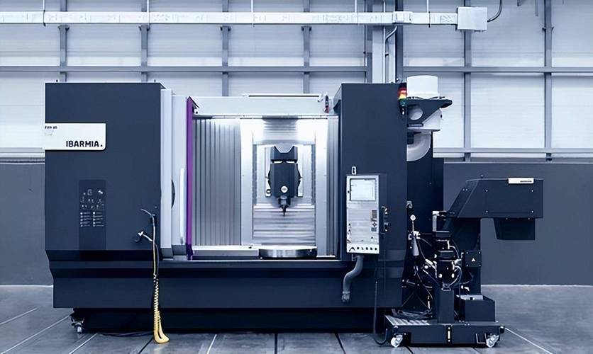
Custom Sheet Metal Machine Guards, Covers & Access Panels
A machine guard is not a cover with a hinge on it. It is a piece of safety equipment that happens to be made of sheet metal, and it is judged on four things: whether it covers the zone it was designed to cover, whether it stays where it was fixed, whether it introduces a new hazard of its own, and whether the machine can still be serviced. This page is about making those four things true in metal.
At a Glance
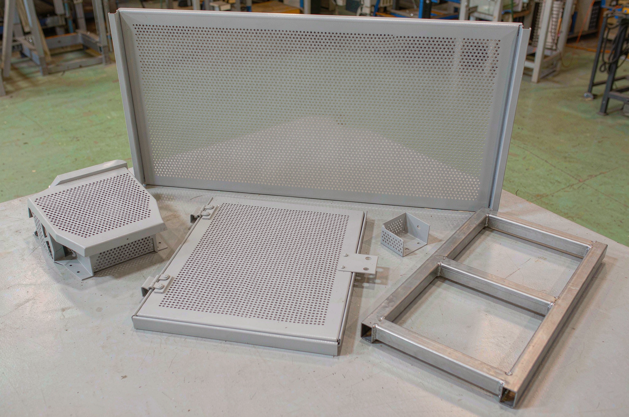
Machine guard sheet metal fabrication is the build-to-print manufacture of the metal panels, covers, doors, frames and brackets that form a guard around a machine — to a design that has already been approved by the machine builder. The fabricator's job is to hold the geometry, the aperture pattern, the mounting interface and the edge condition; the safety decisions that set those numbers — hazard identification, aperture size, safety distance, interlock selection and final validation — belong to the machine's designer. A well-made guard and a compliant guarding system are two different deliverables.
What a Guard Has to Do, and What We Do to It
Machine guarding requirements are usually summarised as four duties, and every one of them converts directly into a drawing feature that someone has to manufacture.
| Duty of the guard | What it becomes on the drawing | What fabrication controls |
|---|---|---|
| Cover the hazard zone | Outline, standoff distance from the moving part, aperture size if the guard is perforated or open | Cut geometry, aperture pattern, formed depth and the resulting envelope |
| Stay in place | Mounting holes, bracket positions, fastener count and size, whether the guard is fixed with a tool or opened by hand | Hole position, weld or fold at the bracket, slot provision for adjustment |
| Not become a hazard itself | Edge radii, burr limits, no sharp corners at hand height, no trapping gap between guard and machine | Deburring, edge break, hemming or rolling, the gap at the mounting face |
| Allow operation and service | Hinge side, swing angle, latch type, inspection window, removable panel size | Hinge hole position, latch keep position, panel weight and handholds |
Read that table as a division of labour rather than a list of features. The first column belongs to the machine builder's safety engineering. The third column is the only one we can honestly own, and it is where most of the failures that reach a production line actually originate: the guard was designed correctly and made slightly wrong.
Openings Are Safety Dimensions, Not Ventilation
The single most common misunderstanding in a guard enquiry is what the holes are for. On a machine guard, the aperture pattern is a safety dimension: the size of the opening, together with the distance from that opening to the hazard, determines whether a finger, a hand or an arm can reach the danger zone. On a machine cover, the same pattern is ventilation or visibility. Different function, different numbers, and the drawing has to say which one applies.
| Guard surface | What it is usually for | What the drawing has to fix |
|---|---|---|
| Solid sheet | Complete physical separation, chip and coolant containment, machine side panels | Outline, formed depth, mounting interface. No aperture decision |
| Perforated sheet | Visibility of the process, airflow, reduced weight, and guarding where the aperture is part of the safety calculation | Hole diameter, pitch, pattern, solid margin widths — and which of those is a safety dimension |
| Expanded metal or woven mesh | Ventilation and visibility with a large open area | Mesh aperture, orientation, frame fixing. Safety distance again belongs to the designer |
| Sheet with a transparent window | Observation of a process that has to be watched | Window material, thickness, fixing method and the retention detail |
We manufacture all four, but we only make the first three from our own sheet metal processes; a polycarbonate or laminated glass window is a purchased part that we mount, and the retention detail matters more than the panel around it, because a window that leaves its frame at speed is worse than no window. Where a window is specified, the drawing should show the fixing, the edge clearance and whether the panel or the window carries the load.
Perforation and the Bend: The Margin That Decides the Part
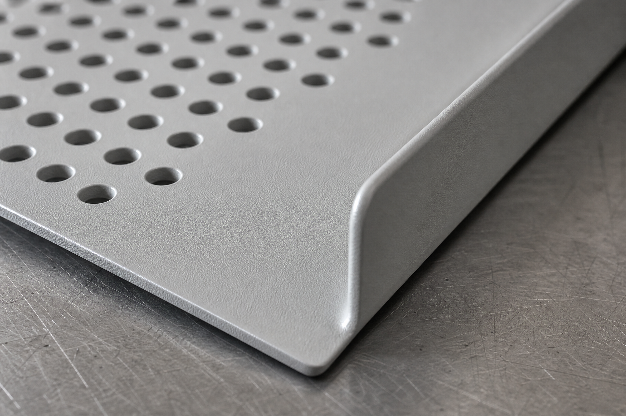
Almost every perforated guard that fails in production fails for the same reason, and it fails at the press brake rather than at the laser. Holes placed too close to a bend line deform as the material is drawn into the bend: they go oval, they tear at the edge, and the row nearest the bend loses its pitch. On a guard, that is not cosmetic — an oval hole is a larger aperture than the one that was calculated.
| Detail | What happens when it is ignored | Practical rule |
|---|---|---|
| Hole-to-bend margin | The nearest holes distort into ovals and the edge row loses pitch | Keep the hole edge at least about 2.5 material thicknesses plus the inside bend radius away from the bend line — a shop rule of thumb, confirmed against the first article |
| Solid zone around mounting holes | A bolt tightened on a perforated field crushes the pattern and the panel creeps | Leave a solid margin of at least one hole pitch around every fastener, and prefer a spot-faced or double thickness pad |
| Open area versus stiffness | A large perforated panel is a spring: it deflects, drums and rattles against the machine | Return flanges on all four edges, or a formed rib, before the pattern is finalized |
| Pattern orientation | A staggered pattern can look correct and still leave a straight shear line across the panel | State the pattern orientation relative to a datum edge, not "as shown" |
| Coating over small holes | Powder bridges across apertures below roughly 3–4 mm and closes them partially or completely | Below that size, decide with the coater whether to mask, to coat and clear, or to leave the panel unfinished |
There is a second, quieter cost to perforation: surface area. A panel with 30 % open area has markedly more surface to coat than its outline suggests, and every hole edge is a place where powder wraps, builds and sometimes bridges. Two identical outlines, one solid and one perforated, are not the same finishing cost, and the quotation should not pretend they are.
A Guard Panel Is a Diaphragm
A 1.5 mm panel a meter wide and six hundred deep, supported at four bolts, is not a rigid object. It deflects under its own weight, it drums when the machine vibrates, and its natural frequency sits close to that of a lot of rotating equipment. The consequences are practical: a rattle that the operator hears all shift, a panel that frets against the paint until bare metal shows, and a mounting hole that elongates because the panel is moving under a bolt that was tightened once.
| Measure | What it does | What it costs |
|---|---|---|
| Return flange on all four edges | The cheapest large gain in stiffness: an edge turned 20–25 mm turns a plate into a shallow tray | One extra bend per edge and a corner relief or weld at each corner |
| Deeper return on the long edges | Stiffens the span that a wide panel actually bends across | Depth has to be clear of the machine and of the moving part |
| Swage or rib across the field | Restores section where a perforated panel has lost it | A press tool or a rolling step, plus a visible line on the finish |
| Additional fixing points | Shortens the unsupported span between bolts | More holes to hold, and more places for the panel to be over-constrained |
| Heavier gauge | Stiffness without geometry | Weight at the hinge, and a heavier panel for one person to lift during service |
Flatness on a guard is a different requirement from flatness on an enclosure door. A guard does not have to seal, so a few millimeters of bow across a meter is tolerable — unless the bow opens a gap at the mounting face, or the panel drums, or it touches a moving part it was meant to clear. That is the conversation to have at drawing review, because the cheapest stiffener is the edge that is already being folded.
Hinged Guards: The Axis Does the Work
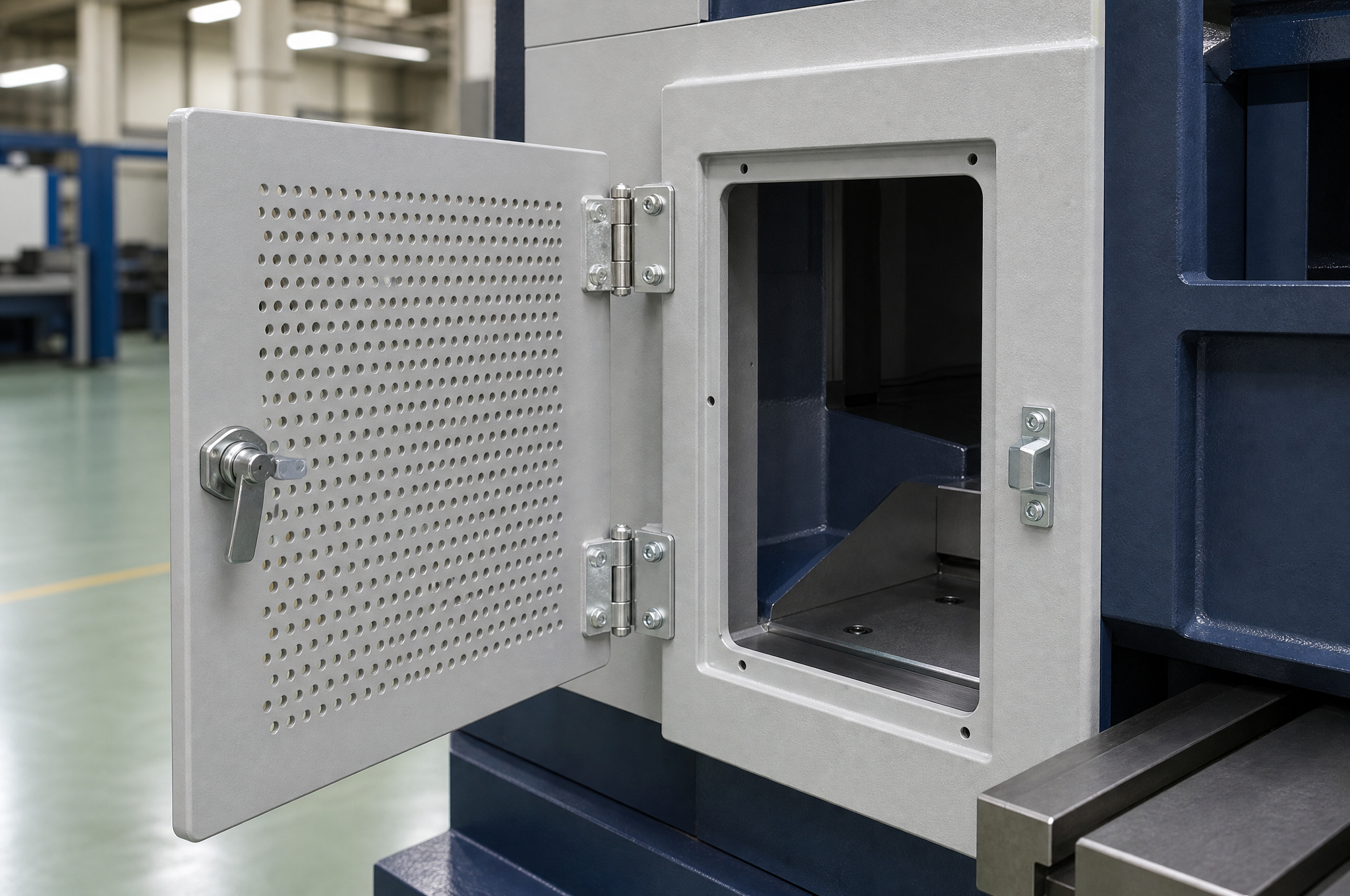
A hinged guard is a door on a machine, and its quality is decided by the hinge axis rather than by the panel. If the axis is not parallel to the frame face, or if it sits at the wrong offset from the panel, the door binds at one end of its swing, the latch needs force to close, and the panel twists as it is pulled shut. On a guard, that twist matters: a panel that closes under stress is a panel that will eventually crack at a hinge weld, or open a gap at the edge that was meant to be covered.
| Decision | What it controls | Where it is usually got wrong |
|---|---|---|
| Hinge axis offset from the panel face | Whether the panel clears the machine frame through the whole swing | The offset is drawn as a nominal dimension and the panel thickness changes later |
| Hinge position along the edge | Load per hinge and how the panel hangs when open | Hinges placed symmetrically by eye rather than by load |
| Swing direction and open angle | Whether the door fouls an operator position, a control station or another guard | The door is designed for the machine, not for the walkway |
| Latch type and keep position | Whether the door closes positively, and whether it can be opened without a tool | A latch chosen after the hinge holes are punched |
| Interlock actuator bracket | Whether a purchased interlock switch can be mounted square to its actuator | Treated as a cosmetic tab rather than a dimensional interface with a purchased device |
| Clear opening when open | Whether a hand, a tool or a component can get in for service | The panel size is checked, the working clearance is not |
Belt and Chain Covers: Geometry Around Something That Moves
A drive cover is the one guard where the inside of the part matters as much as the outside. It has to clear a belt that whips, a pulley that grows when it gets hot, and a tensioner that moves when it is adjusted. It also has to come off, usually in a space the maintenance technician does not control.
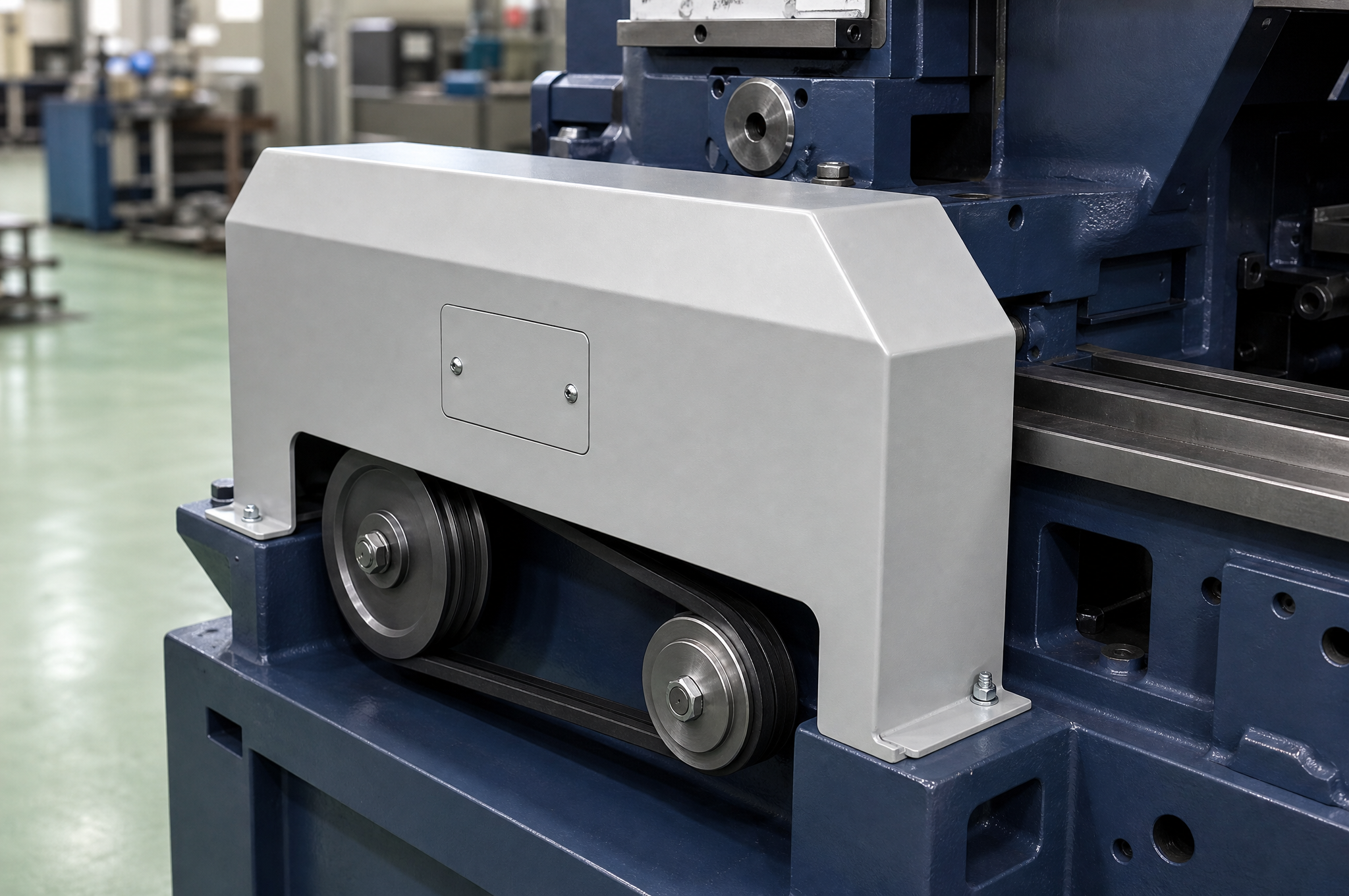
| Requirement | What it means in sheet metal | What to watch in fabrication |
|---|---|---|
| Clearance to the moving belt | The internal envelope is set by the largest pulley plus the belt's running envelope, not by the pulley's static outline | Formed depth available from one sheet, or a folded and welded box where the depth is too great |
| Removal in service | The cover lifts off or swings clear without draining the drive or removing the motor | Slot direction, handholds, and whether the fasteners stay captive |
| Split covers | Two-piece covers where the guard has to fit around a shaft that cannot be dismantled | The joint line, its overlap and the fastener positions that keep the joint closed |
| Oil, coolant and drain | A closed cover collects what leaks off the drive | A deliberate drain gap or a lowest-point opening, and a finish that tolerates the fluid |
| Inspection without removal | A small plate or window over the belt tension check | Plate flatness on a curved face, and screws that do not project into the belt path |
Chain drives add a second consideration: a chain guard is often also the oil retainer, and the bottom of the cover is where the oil sits. That makes the lowest fold a wet corner, so a folded and welded box in painted steel will corrode there first unless the drain and the finish are decided together. It is a small design point that turns into a warranty conversation two years later.
Welded Guard Frames: Twist Is the Enemy
Guard frames are usually made from square or rectangular tube and welded at the corners. The dimension that matters is not the outside size but whether the four mounting faces are coplanar: a frame can be square in plan, correct in both diagonals, and still be twisted, and a twisted frame puts a guard panel into a permanent bend. The panel then either bolts up with a gap at one corner or pulls the frame straight as it is tightened, which preloads the panel and makes it drum.
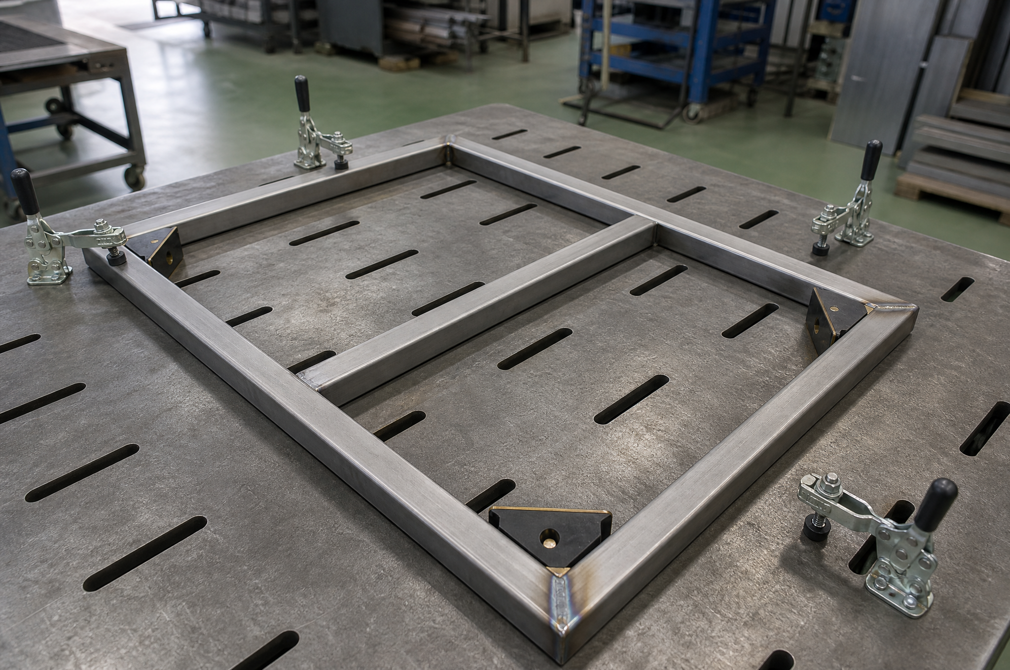
| Control | Why |
|---|---|
| Weld on a flat table with clamps and squares | The table holds the frame in one plane while the welds shrink; a bench top is not flat enough to reference |
| Sequence from the center outward, opposite corners alternately | Balances the shrinkage so the frame does not pull into a bow or a twist |
| Smallest weld that carries the load | Weld volume is shrinkage; a 4 mm fillet where a 3 mm one is sufficient adds distortion for nothing |
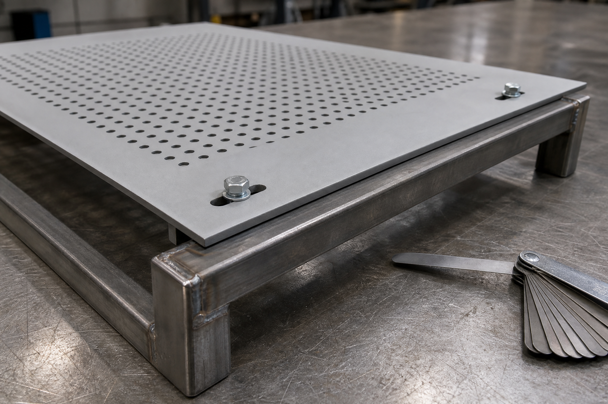
| Check coplanarity, not just diagonals | Diagonals catch a rhombus; they do not catch a twist. Check all four faces with a feeler on the table, or on a surface plate |
| Straighten before drilling, not after | Holes drilled into a distorted frame are in the wrong place once it is straightened |
| Machine or drill mounting holes after welding | The weld moves the frame; the hole pattern should be established on the finished frame |
The last row is the one that saves the most arguments. A frame drilled before welding has holes positioned by a fixture that the weld then distorts away from. A frame drilled after welding, from a common datum, has holes that are correct on the object that will be bolted to the machine.
Mounting to the Machine: Locate, Then Fasten
Most guard fitting problems are constraint problems rather than accuracy problems. A panel with four round holes in a rigid frame, bolted to a machine with four studs, is over-constrained: it can only fit if every hole and every stud agree to within the sum of the clearances. They rarely do, and the panel is then pulled into position by the bolts — which is where the twist comes from.
| Fixing scheme | What it tolerates | Where it is the right choice |
|---|---|---|
| One round hole, one slot, two clearance holes | Frame-to-frame variation in one axis, and a small amount in the other | The default for a bolted guard panel. Locates positively and still assembles |
| Two round holes on a diagonal, two slots | Dimensional variation in both axes | Large panels where the frame is welded and cannot be held tightly |
| All slotted holes | Everything, including the position | Only where the guard is adjusted on site against a machine feature. It cannot locate itself |
| Spacers or shims at the mounting face | Out-of-plane variation in the machine frame | Retrofit guards on machines whose frames are not flat, where the gap must be closed without bending the panel |
| Captive fasteners | Losing the screw during service | Access panels opened frequently, and any cover removed above a running machine |
Two consequences follow for fabrication. First, the hole pattern should be established from one datum — usually a machine-side interface, not the panel outline — so that the tolerance accumulates in one direction instead of in two. Second, the slot direction has to match the direction in which the real variation occurs; a slot that runs the wrong way is decoration. On a set of guards for one machine, the fastest way to find out is a trial fit on the bench with the frame present, which is a service we can perform when both parts are in our scope.
Edge Quality: The Guard Must Not Become the Hazard
Cut and punched edges have burrs on one face and a sharp corner on the other, and a guard is handled far more often than an enclosure: it is fitted during build, removed for service, leaned against a wall, and reached past by an operator every shift. A guard that cuts the person maintaining it has failed the same duty it was built to satisfy, and it is the cheapest failure to prevent.
| Edge | Why it is exposed | How it is dealt with |
|---|---|---|
| Laser-cut outline | A sharp corner on both faces, with a fine dross line on the underside | Deburr both faces, or a small edge break on any edge at hand height |
| Punched perforation | Each hole has a roll-over on one side and a burr on the other | Punch from the face side and deburr the exit, or specify a pattern that is punched and then finished |
| Sheared blank edge | A pronounced burr where the shear terminates | Deburr, or place the sheared edge where it is not reachable |
| Corner of a folded return | A three-thickness corner that stays sharp through coating | Corner relief, a radius, or a hem |
| Window aperture | The edge a hand goes through or a cable rubs against | Edge break plus a grommet or edge trim where cables pass |
Coating hides a burr rather than removing it: 60–120 µm of powder over a 0.3 mm burr is still a burr, and it is now a burr that can chip off into the machine. That is why the deburring operation belongs before finishing and why an edge check belongs in the inspection plan rather than in the packing note.
Materials and Finish, Chosen by What the Machine Does
The substrate for a guard is chosen by the environment the machine creates, not by the load the guard carries. A guard is rarely strength-limited; it is usually corrosion-limited, weight-limited or cleaning-limited.
| Substrate | Where it is right | What to watch |
|---|---|---|
| Cold-rolled steel, typically 1.0–2.0 mm | General machine guards and covers in a dry plant, painted | Every cut edge and uncoated interior is a corrosion start; the coating must reach the inside faces that see coolant |
| Hot-dip galvanized steel | Outdoor machines, washdown areas, guards that will never be painted | The zinc at a cut or punched edge is not restored; a zinc-rich touch-up or a design that keeps edges dry |
| 304 stainless | Food, beverage and pharmaceutical equipment; washdown with mild detergents | Welds need finishing and passivation; edges are still sharp and still need deburring |
| 316 / 316L stainless | Chloride exposure, coastal plants, aggressive cleaning chemistry | Higher material cost, and machining that is slower; confirm the actual chloride level before specifying it |
| Aluminum | Weight-sensitive guards, large covers that one person has to lift, anodized finishes | Welding distorts more and softens the temper; a folded or riveted construction is often the better answer |
Finish on a guard has two jobs that are sometimes in conflict: protect the steel, and not interfere with the fit. Powder coating is the default for painted guards, and the masking question is the same one that decides assembly: hinge faces, latch keeps, bonding points and any sliding contact should be identified on the drawing before the panel is coated, because a masked face is a manual operation and an unmasked one is a fit problem.
Material grades and their corrosion behavior are covered in more depth on the materials page and, for stainless, on the stainless steel enclosure page. Coating routes sit on the surface finishing page.
Standards, and the Line Between Making and Certifying
Guard enquiries quote standards for a reason: the document is how a machine builder proves that the guarding was designed to a recognized basis. It is worth being precise about which document says what, because the names get used interchangeably in emails and they are not interchangeable.
| Document | What it addresses | Who applies it |
|---|---|---|
| OSHA 29 CFR 1910.212 | General requirements for machine guarding in US workplaces: guarding at the point of operation and at rotating parts, ingoing nip points, and protection from flying chips and sparks; the guard must not create a hazard of its own | The employer and the machine supplier placing the machine into service |
| ISO 14120 | Design and construction of fixed and movable guards — the guard as a product | The machine designer, as part of the risk reduction process |
| ISO 13857 | Safety distances that prevent hazard zones being reached through openings | The machine designer, when setting aperture size and standoff |
| ISO 14119 | Interlocking devices associated with guards — selection and arrangement | The machine designer and the safety controls supplier |
| ISO 13855 | Positioning of safeguards with respect to approach speeds | The machine designer, for the overall layout |
| EU Machinery Regulation (EU) 2023/1230 | Replaces the Machinery Directive for equipment placed on the EU market; applies from 20 January 2027 and sets requirements for guards including robustness, fixing, the absence of additional hazards and maintenance access | The manufacturer placing the machine on the market, with the technical file |
The Machinery Regulation date is worth planning against rather than reading about. A guard designed in 2026 for a machine that will ship after January 2027 is being designed under the incoming regime, and the questions a European customer asks at enquiry stage — documented fixing, edge condition, maintenance access, material and finish records — are the same questions that document will require them to answer.
What we can do is make the manufacturing side easy to document: dimensions recorded on the drawing's own critical features, first article inspection on the first part of a revision, material certificates where the order requires them, and trial-fit records where the frame and the panel are both ours. Those are the inputs a technical file needs from the fabrication side, and they are the ones most often missing when a customer assembles a file at the end of a project.
Inspection, and Why Trial Fit Beats a Dimension Report
Guard components are large, thin and awkward, and a report full of individual dimensions can be entirely green while the assembly does not fit. The inspection plan below is built around what the customer does with the part: mount it, open it, service behind it.
| Check | How | What it establishes |
|---|---|---|
| Overall dimensions and formed depth | Tape or height gauge | The envelope the guard occupies on the machine |
| Mounting hole positions | Height gauge from the stated datum, or a checked template | That the guard lands on the machine's studs without forcing |
| Aperture pattern | Hole diameter and pitch, sampled across the field; pitch checked near the bend | That the pattern matches the approved drawing and did not deform at the bend |
| Panel flatness | Straightedge and feeler across the field, and at the mounting face | That the panel does not rock on its frame or drum in service |
| Frame squareness and coplanarity | Diagonals plus a feeler check of all four faces on a flat table | That the frame is not twisted, so the panel is not preloaded |
| Hinge and latch positions | Template or height gauge, relative to the machine-side datum | That the door swings without binding and the latch meets its keep |
| Weld condition | Visual; weld size at the specified joints | Structural continuity, and no spatter or undercut in a visible area |
| Edge and burr condition | Visual and tactile at hand-height edges and around every aperture | That the guard does not introduce a handling hazard |
| Coating thickness and coverage | Magnetic or eddy-current gauge; visual inside corners and inside the perforation | That the specified film is present where corrosion starts |
| Trial fit | Panel mounted on its frame, bolts in place, gaps and swing checked | That the set assembles before it reaches the customer's line |
What the Guard Drawing Has to Carry
Guard drawings often arrive as a machine general arrangement with the guard shaded and a note saying "manufacture to suit". That is a design instruction, not a manufacturing drawing, and the gap between the two is where rework lives.
| Item | What to state | What goes wrong without it |
|---|---|---|
| Guard type and function | Fixed, hinged, removable, sliding; what hazard it covers | The fixing method and the edge treatment are chosen by default rather than by function |
| Outline and formed depth | Overall dimensions, return depths, and the internal envelope that must stay clear | The guard clears the machine in the drawing and fouls a moving part in reality |
| Aperture pattern | Hole size, pitch, pattern, orientation, solid margins, and whether the aperture is a safety dimension | The pattern is optimized for looks or airflow and a safety distance moves with it |
| Mounting interface | Machine-side datum, hole positions and sizes, slot direction, fastener type | Over-constraint: the panel bolts up but pulls the frame into a twist |
| Hinge and latch | Hinge type, axis position, side, open angle; latch type and keep position | The door binds, or the latch is bought after the holes are punched |
| Interlock bracket | The switch maker's mounting drawing, actuator and body positions | The bracket is a tab, and the switch cannot be aligned on site |
| Edge requirements | Which edges are handled, hemmed, radiused or trimmed | Burrs at hand height, discovered by the installer |
| Substrate and finish | Material, gauge, color, faces coated, masked areas | The interior of a coolant-facing cover is left bare |
| Structural notes | Where stiffening is expected, and any load the guard carries (a window, a switch, a cable tray) | Stiffening is added after the first panel drums, at the customer's cost |
| Inspection and trial fit | Critical dimensions, sampling, and whether a trial fit is required | "Inspection to drawing" is quoted, and nobody agrees what was measured |
Guard Types We Fabricate
The list below is the shape of the work rather than a catalog: every item is made to a drawing, and most projects combine several of them into one set for one machine. What changes between them is the structure, the fixing method and how much of the guard has to move.
Fixed Guard Panels
Solid or perforated panels bolted to the machine and removed only with a tool. Formed returns on the long edges, mounting flanges or brackets at the ends, and a mounting pattern taken from the machine interface.
Perforated Guard Panels
Laser-cut or punched patterns to a customer-defined aperture and pitch, with solid margins around fasteners and at every bend. The pattern is treated as a drawing dimension, not a finish.
Hinged Access Guards
Doors and inspection panels on weld-on or bolt-on hinges, with latch keeps and interlock brackets positioned to the purchased hardware rather than by eye. Swing and clear opening checked at trial fit.
Belt, Chain and Pulley Covers
Folded or fabricated covers around a moving drive, with clearance for the running belt, an inspection plate or window, a drain at the lowest point, and flanges that let the cover come off in service.
Welded Guard Frames and Supports
Square or rectangular tube frames welded on a flat table, checked for coplanarity rather than only for diagonals, with mounting holes drilled after welding from a common datum.
Machine Covers, Side Panels and Chip Shields
Formed covers and side panels that close a machine, contain chips and coolant, and still come apart for service. Where a cover also has to contain fluid, the corner and the drain are the design decisions.
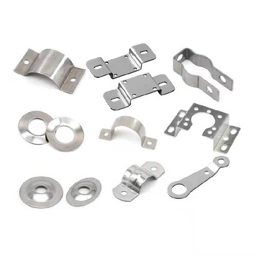
Brackets and Mounting Interfaces
Hinge plates, latch keeps, interlock switch brackets, standoffs and interface plates. Small parts with high information density, and the ones most often revised after the first machine is built.
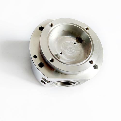
Machined Interface Parts
Where a guard needs a turned or milled interface — a precision bushing, a locating block, a shaft support — it is machined on our CNC side rather than formed, which is the practical advantage of buying sheet metal and machined parts from one supplier.
Machined components are covered under CNC machining services; the sheet metal processes behind the panels — laser cutting, punching, bending and welding — are set out under sheet metal fabrication capabilities.
What Moves the Price of a Guard
Guards are quoted per part or per set, and the price is decided by a handful of features that are all visible on the drawing. The list below is ordered roughly by how much each one moves a quote.
| Driver | Why it costs | Where there is room to trade |
|---|---|---|
| Perforation density | Hole count is machine time: a dense field is slow to laser and needs a press tool to be economic at volume | Standardize the pattern across a family of guards so one program and one tool serve several parts |
| Panel size against gauge | Large thin panels need returns, stiffeners or a heavier gauge to stay flat, and they are awkward to handle and coat | Split a very large guard into two panels with a joint rather than stiffening one |
| Welding | Fit-up, fixture, dressing and a distortion check; a folded part avoids all four | Fold where the geometry allows, and weld only the joints that carry load or close a fluid path |
| Number of parts in the set | Each part carries its own program, setup, inspection line and packing | Consolidate brackets into the panel where the design permits |
| Finishing area | Perforated and folded parts have far more surface than their outline, and coating cost follows area | Leave interior faces bare where the environment allows it |
| Masking | Each masked face is manual before coating and an inspection after it | Consolidate masked areas onto one face, or design the joint so masking is unnecessary |
| Tolerance class | Holes positioned from a common datum in one setting are routine; an interface held tightly across two operations is not | Tighten only the holes that locate against the machine |
| Trial fit | Assembly time on the bench with the frame present, plus the record | Reserve it for the first article and for sets where the frame is also ours |
| Volume and repeatability | Setup amortizes across the batch, and a repeat order on the same drawing is significantly cheaper than the first | Order the annual quantity in call-offs against one setup |
What to Send With a Guard Enquiry
A guard enquiry that arrives with a drawing, a machine interface and the purchased hardware identified can be quoted and reviewed in a day. One that arrives with a photograph and a machine model can be quoted too, but the quote will carry assumptions that the first article has to pay for.
| Send this | Why it changes the quote or the part |
|---|---|
| Dimensioned 2D drawing plus the 3D model | The drawing controls inspection; the model catches interference the drawing does not show |
| Machine-side interface drawing or frame drawing | The hole pattern is only correct relative to the machine, and this is the document most often missing |
| Guard type and fixing method | Fixed, hinged, removable or sliding decides the structure, the edge treatment and the hardware |
| Aperture pattern, with its purpose stated | Safety dimension or ventilation — the answer decides whether the pattern can be optimized at all |
| Hardware: hinge, latch, interlock switch make and model | Brackets and keeps are machined to the hardware, not to a nominal |
| Substrate, gauge and finish | Stiffness, mass, weld parameters, coating scope and cost |
| Edges that will be handled | Which edges need an edge break, a hem or a radius |
| Internal envelope that must stay clear | The moving part the guard was designed around, not just its static outline |
| Inspection and trial-fit requirements | Report scope, first article, and whether the frame will be supplied for fitting |
| Quantities: prototype, pilot, annual | Setup amortization and whether a press tool or fixture is worth building |
If the safety-related numbers are still open, say which ones. A quote that names its assumptions is easier to compare against a second supplier, and it makes the boundary between the machine design and the fabrication explicit from the first email.
Frequently Asked Questions
What is machine guard sheet metal fabrication?
Can you manufacture guards to our existing approved design?
What is the difference between a fixed guard and a movable guard in manufacturing terms?
Do you determine the aperture size or the safety distance for a guard?
Can you make perforated machine guard panels?
Which materials and thicknesses do you use for machine guards?
How do you stop large guard panels from drumming or distorting?
Can you supply a complete set: panels, frame, hinges, brackets and fasteners?
Do you supply interlock switches or safety control systems?
How is a guard inspected before shipment?
What is the difference between an ISO 14120 guard and an OSHA-compliant guard?
What information do you need to quote a machine guard?
Send the Guard Drawing and the Machine Interface
The review that decides the price happens before the sheet is nested. Send the dimensioned drawing, the machine-side hole pattern, the aperture pattern with its purpose, the hinge latches and interlock hardware, the material and finish, and the inspection scope. You get a response on structure, gauge, stiffening, edge treatment, coating and trial fit — with anything that cannot be built as drawn raised at that point rather than at first article.
Request a Guard QuoteSTEP, IGES, DXF, DWG or PDF drawings · single panels or complete guard sets
See the sheet metal processes behind every guard →