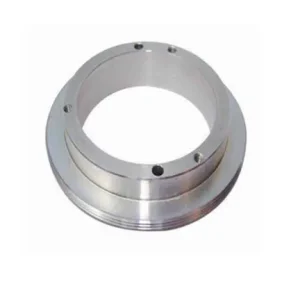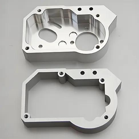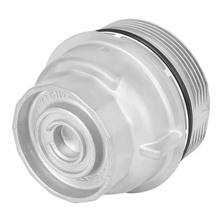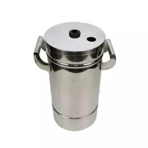
3/4/5 Axis Rapid Prototype CNC Precision Metal Parts
Processing Capabilities
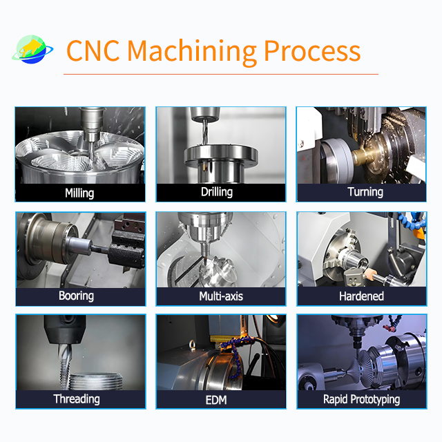
Supported Number of Axes: 3 – axis/4 – axis/5 – axis simultaneous machining
Maximum Workpiece Size: 1500×800×500mm (Customizable and expandable to 2000mm)
Processing Accuracy: ±0.005mm (Regular), ±0.002mm (High – precision mode)
Surface Roughness: Ra0.1μm (Mirror polishing), Ra0.2 – 3.2μm (Regular processing)
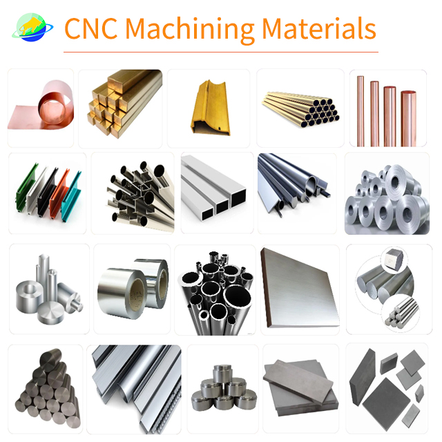
Applicable Materials
Aluminum Alloys: 6061/7075/ADC12 (Minimum wall thickness for thin – walled parts is 0.3mm)
Stainless Steels: 304/316L/17 – 4PH (Hard – state machining supported)
Titanium Alloys: TC4/Gr5 (Including inert gas protection process)
Others: Brass H59/H62, Nickel – based Superalloys (Inconel 718)
Description
3/4/5-Axis CNC Precision Metal Prototype Parts
Custom CNC-machined aluminum, stainless steel, titanium and other metal parts produced from your CAD files or drawings — for functional prototypes, fit and assembly validation, engineering testing and low-volume production.
*Typical for standard geometries. Actual lead time depends on material, geometry, quantity, tolerance, finishing and inspection requirements.
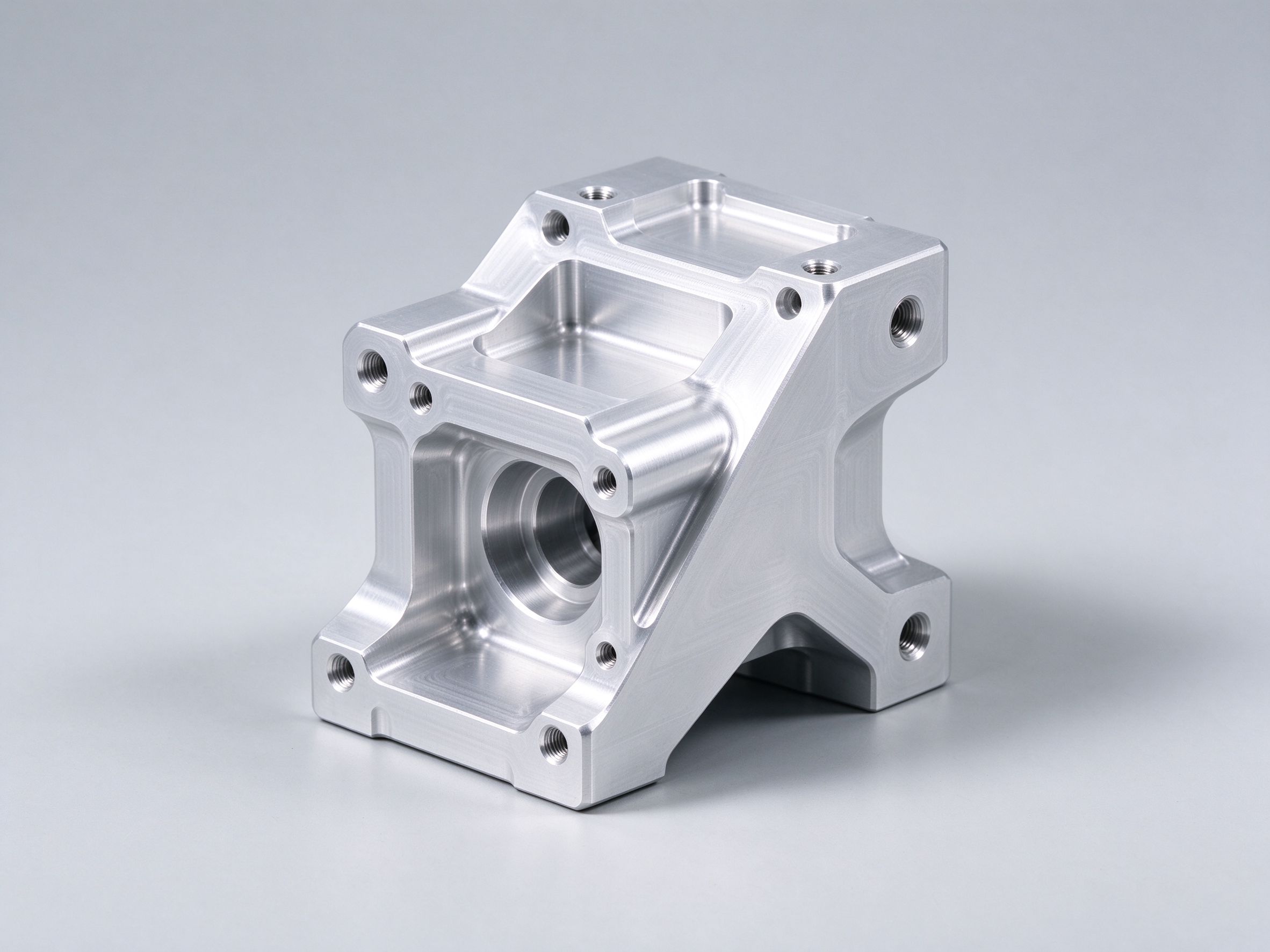
What Are These CNC Prototype Parts Used For?
These are functional metal parts machined on CNC mills and lathes in small quantities to validate a design before mass production. Engineers use them to prove form, fit and function with the real material and the real manufacturing process.
Fit & Assembly Validation
Verify mounting interfaces, hole locations, threads and how mating components line up against the rest of the assembly.
Functional Testing
Test load, movement, heat, wear and real mechanical behavior in the actual product environment, not just in simulation.
Design Verification
Confirm that the real geometry, dimensions and interfaces match the CAD model and the engineering intent.
Pre-Production / Pilot Builds
Validate manufacturability, assembly and process assumptions before committing to tooling or larger production batches.
Which CNC Axis Configuration Does Your Part Need?
More axes are not automatically better parts. The right configuration depends on geometry, tool access, setup strategy, tolerance requirements and production economics. Choosing 5-axis for a simple prismatic part usually adds cost without benefit.
| Configuration | Suitable for |
|---|---|
| 3-axis | Faces, pockets, slots, holes and conventional prismatic parts machined in standard orientations. |
| 4-axis | Parts requiring machining around a rotary axis, or additional features on side faces. |
| 5-axis | Multiple angled surfaces, complex contours and features needing improved tool access across several faces. |
3-axis on a complex housing
5-axis on the same housing
Materials for CNC Prototype Parts
Prototype materials are chosen to prove a specific engineering point. The table below maps each stock material to the kind of component it is typically used to validate — not a general catalog.
6061-T6
General-purpose prototype housings, brackets, fixtures and structural parts. The default starting point for most functional metal prototypes.
7075-T6
Higher-strength, weight-sensitive components where 6061 would be too weak or require thicker sections.
304 / 316L
Corrosion-resistant functional parts, housings and mechanical components. 316L for stronger corrosion exposure.
Grade 5 (Ti-6Al-4V)
High strength-to-weight applications where weight, temperature and mechanical performance all matter together.
Brass
Fittings, electrical and mechanical components, and parts requiring conductivity or good machinability.
POM · PEEK · Nylon · PC · ABS
Engineering plastic prototypes where a polymer part is the intended end material, or for non-structural fit checks.
How Should You Choose the Material for a CNC Prototype?
Start from what the prototype has to prove, then back into the material. This is the decision we run with engineers before quoting.
| What are you testing? | Possible material direction |
|---|---|
| General mechanical fit and assembly | 6061 aluminum |
| High strength with low weight | 7075 aluminum |
| Corrosion resistance | 304 / 316L stainless |
| Strength, temperature or weight performance | Titanium Grade 5 |
| Low-friction plastic component | POM / PEEK |
| Electrical or conductive component | Brass / copper |
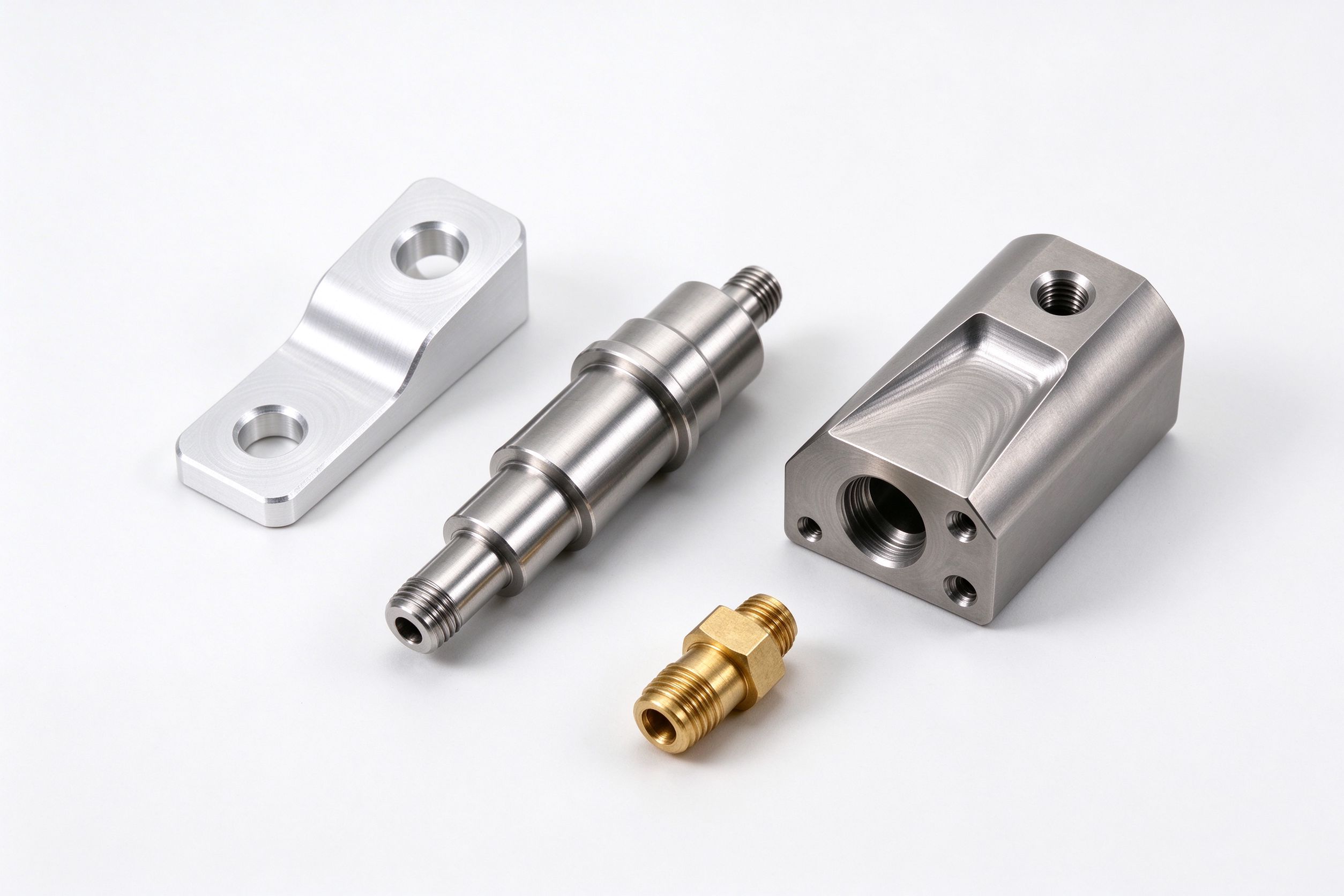
Material selection should be based on what the prototype needs to prove, rather than choosing the least expensive stock. If you send the drawing, our engineers will confirm the direction during DFM review.
How These CNC Prototype Parts Are Manufactured
Every order follows the same engineering path. Machining is one step in a review → machine → verify loop, not the whole story.
CAD / Drawing Review
Confirm material, dimensions, tolerance, GD&T and finish before any machine time is booked.
DFM Review
Check wall thickness, internal radii, hole sizes, deep pockets, tool access and required setups.
Machining Strategy
Choose 3/4/5-axis, milling or turning, workholding and tooling for the geometry and tolerances.
CNC Machining
The part is produced on the selected machine under the approved process plan.
Inspection
Critical dimensions and interfaces are verified against the drawing before shipment.
Finishing & Packaging
Anodize, bead blast, polish, passivate, plate or paint as required, then package for transit.
CNC Prototype Tolerance & Inspection
Typical prototype tolerance is ±0.01 mm; ±0.005 mm is achievable on selected critical features when the geometry and process allow it.
Final achievable tolerance depends on part size, material, feature geometry, machining process, workholding, thermal conditions and inspection method. Tolerance is a capability of the whole process, not a label on the shop door.
Critical features may include: bearing bores · shaft fits · mounting interfaces · sealing surfaces · threaded features.
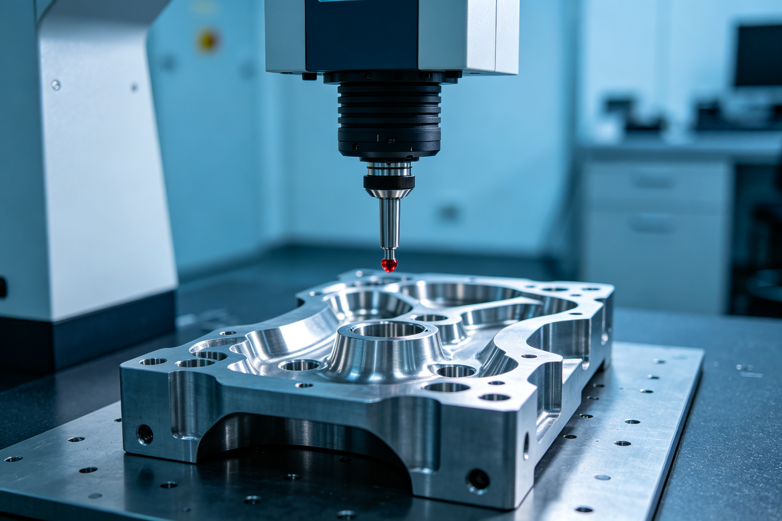
Inspection methods used: CMM, micrometers, height gauges, optical measurement, thread gauges and surface measurement where required. Reports are issued against the dimensions you specify on the drawing, rather than a single blanket claim.
Design Considerations for 3/4/5-Axis CNC Parts
These are the geometry decisions that most often change a prototype from "machinable" to "accurate". Flag them in the drawing and the first-fit probability goes up.
Internal corners
Milling tools are round, so sharp internal corners usually require larger radii or special corner strategies.
Deep pockets
High depth-to-width ratios increase tool deflection and vibration, which degrade surface finish and accuracy.
Thin walls
Thin walls may deflect during machining or spring back after clamping, affecting final dimensions.
Small holes
Very small holes raise tooling and process difficulty; confirm drill diameter and depth on the drawing.
Threads
Specify thread standard, size, class and depth (UNC / UNF / metric) rather than leaving it to the shop.
5-axis features
Complex angled surfaces need tool-access planning before programming; not every angled face is suitable for 5-axis.
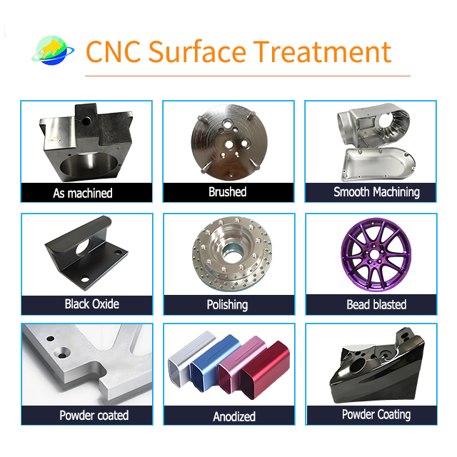
Surface Finishing for CNC Prototype Parts
Finish availability depends on the material and the required function — not every finish applies to every part.
| Finish | Typical purpose |
|---|---|
| As-machined | Fastest option for functional testing and geometry validation. |
| Anodizing | Aluminum corrosion protection and a range of surface appearances. |
| Bead blasting | Uniform matte appearance across visible surfaces. |
| Brushing | Directional satin texture for visible components. |
| Polishing | Smooth or reflective appearance for cosmetic or sealing faces. |
| Passivation | Stainless steel corrosion protection after machining. |
| Plating | Functional or appearance requirements (zinc, nickel, chrome, etc.). |
| Painting | Color coding or an additional protective coating. |
From Prototype to Low-Volume Production
The value of a prototype supplier is not only making one part — it is carrying the same machining route from the first CAD model into a pilot batch and repeat production, without a second learning curve.
The same machining route can be reviewed across prototype, pilot and repeat production depending on geometry, quantity and process requirements. We do not quote a blanket "1 to 10,000 pieces" number; each stage is reviewed against its own volume and tolerance needs.
Featured CNC Prototype
A representative 5-axis prototype project — what was made, what was tested and what the outcome was. Your part will be reviewed against the same criteria.
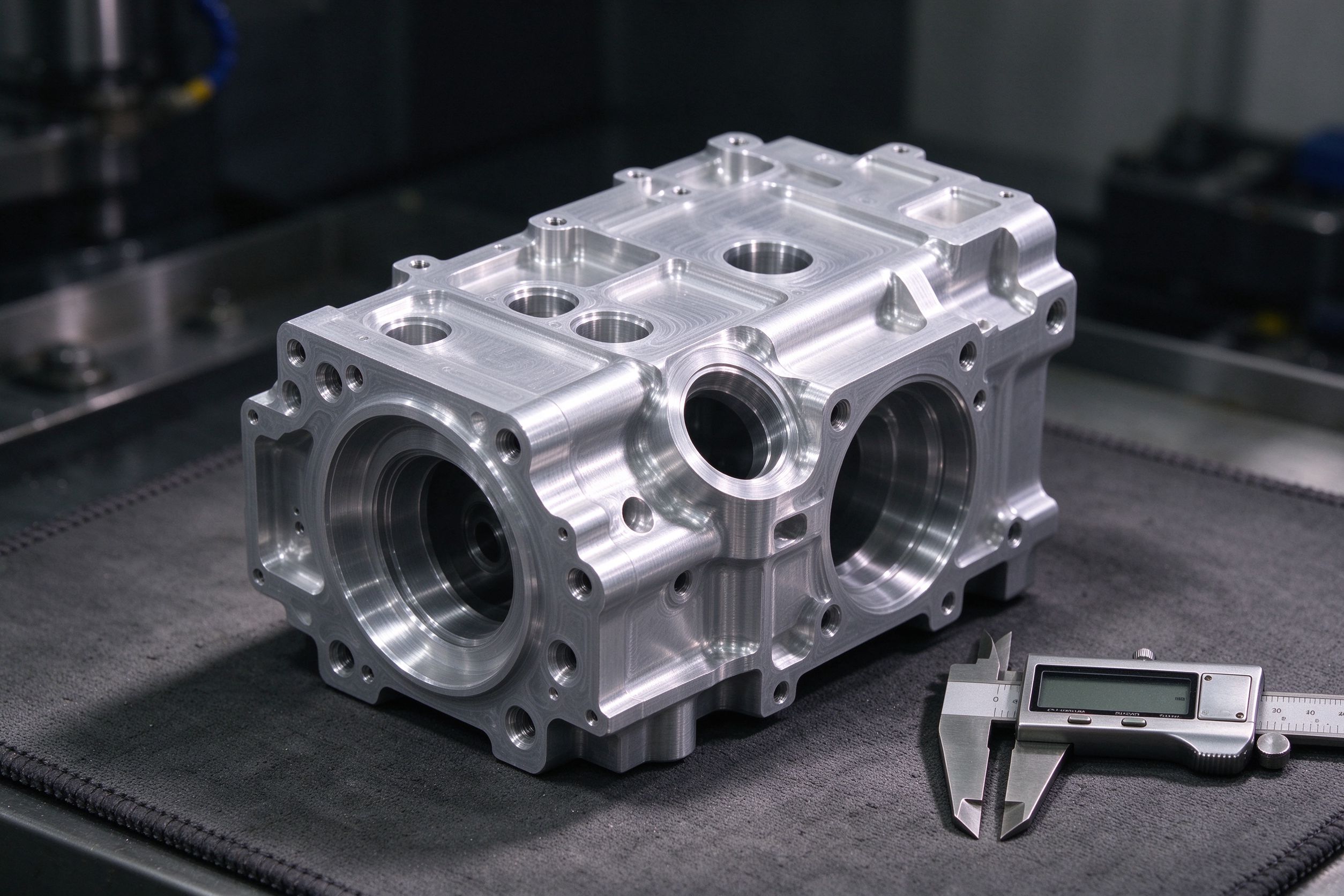
Complex 5-axis aluminum housing
- Part
- 5-axis machined housing with angled mounting interfaces
- Material
- Aluminum 7075-T6
- Process
- 5-axis CNC milling
- Quantity
- 2 pcs (functional prototype)
- Purpose
- Fit and mounting validation against a mating bracket
- Critical features
- Angled bores, datum mounting faces, sealing surfaces
- Inspection
- CMM verification of bore and interface dimensions
- Finish
- Matte anodizing
- Outcome
- Both housings mated on the first fit check; design proceeded to a pilot batch with the same machining route.
What We Need to Manufacture Your Part
Send these and the first quote is a real engineering response, not a placeholder number. Files accepted: STEP, STP, IGES, IGS, X_T, DWG, PDF.
| Required information | Example |
|---|---|
| 3D CAD | STEP / STP / IGES / X_T |
| 2D drawing | PDF / DWG (with GD&T and critical dimensions) |
| Material | 6061-T6 / 7075-T6 / 316L / Ti Gr5 … |
| Quantity | 1 / 5 / 20 pcs |
| Tolerance | General tolerance plus which dimensions are critical |
| Surface finish | As-machined / anodizing / bead blasting … |
| Thread | UNC / UNF / metric (size, class, depth) |
| Inspection | CMM report / dimensional report / as-machined only |
| Delivery | Target date and destination |
Why Goldcattle
A precision metal machine shop with the engineering review step built in — not just a machine.
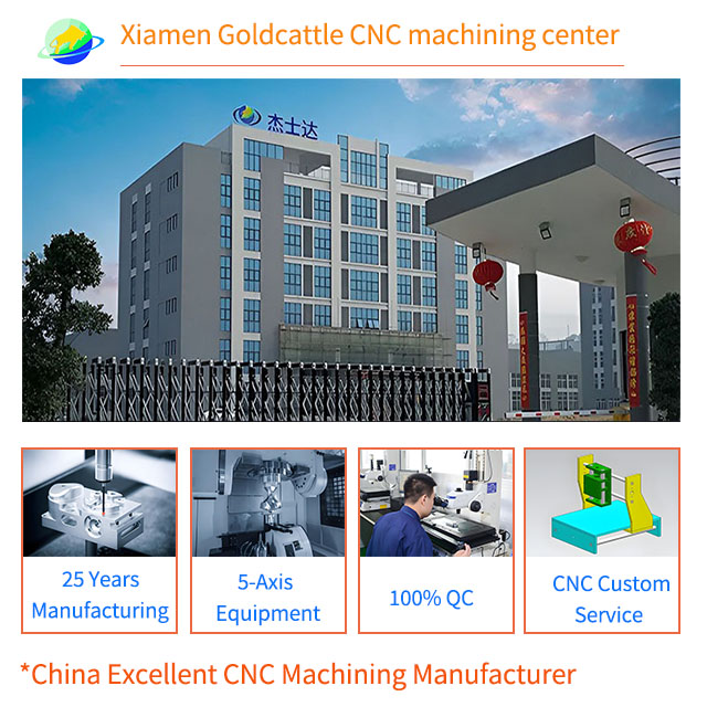
- 1998Precision metal machining since 1998, focused on custom parts rather than catalog items.
- 3·4·53-, 4- and 5-axis CNC milling and turning, with the axis chosen for the geometry.
- REVIEWEngineering and DFM review before machining, not after the part is already cut.
- INSPECTDimensional inspection against your drawing, reported on the features you flag.
- PATHPrototype → pilot → low-volume production continuity on the same route.
Frequently Asked Questions
Can CNC machining produce a single prototype?
What is the typical prototype lead time?
What materials can be used?
When do I need 5-axis machining?
What tolerance can you hold?
Can prototypes receive anodizing or other finishes?
Can you provide dimensional inspection reports?
Can the same supplier support production later?
Request Custom CNC Prototype Parts
Upload your 3D CAD model or drawing. Tell us the material, quantity, critical tolerances and finishing requirements. Our engineering team will review the part and confirm the appropriate 3-, 4- or 5-axis machining process before quoting.