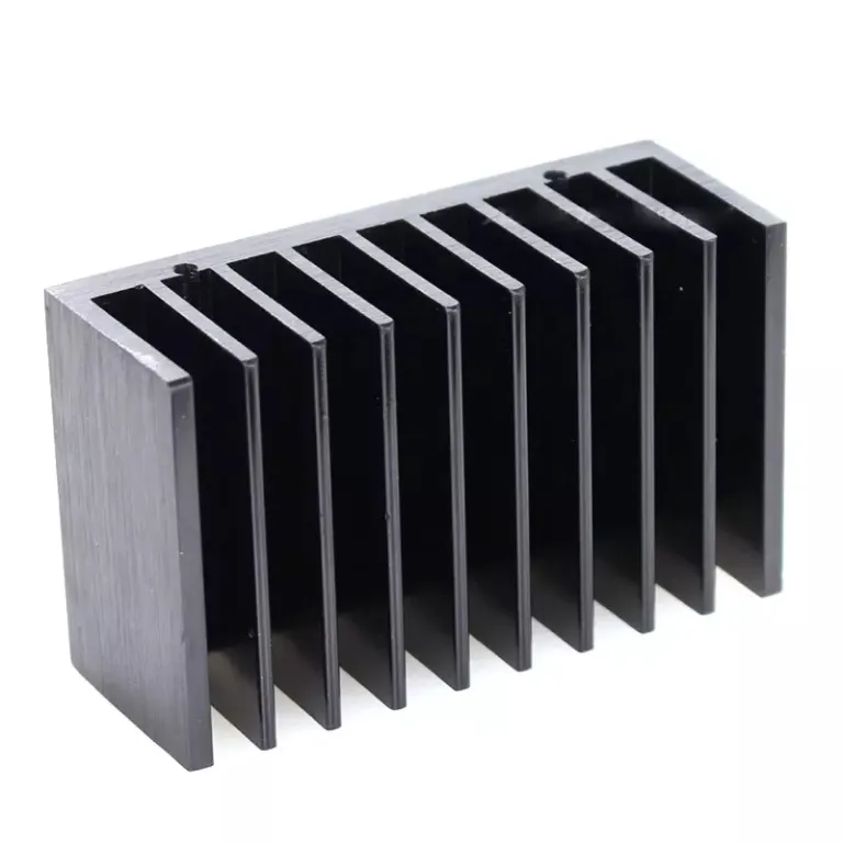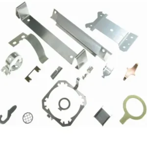


Custom Metal Stamping Parts | Brass/SS/Al OEM
Place of Origin : Xiamen, China
Brand Name : JSD
Model : MS-08
Support : OEM Service
Certification : ISO9001
Surface Finis : sandblasted, polished, anodized, galvanized, nickel plated, chrome plated, etc.
Size : As per customer’s requirement
Material : Steel/Aluminum/Copper/316 Stainless Steel etc.
Thickness : Customized
Type : Stamping Hardware
Description
Custom Brass, Stainless Steel & Aluminum Stamped Components
Xiamen Goldcattle Plastic & Metal Products Co., Ltd. makes stamped metal parts to your drawings. This page is organised by material, because the grade and temper you choose change how the part forms, how the die is built, how the edge is finished and how the finished dimensions are checked.
- Brass
- Stainless steel
- Aluminum
- Build-to-print
- Custom tooling
- Material basisGrade and temper from your drawing
- ToolingDie route selected from geometry and volume
- PrototypeFrom 1 piece where no die is needed
- Quality systemISO 9001:2015 certified
- EstablishedFounded in 1998
At a Glance
This is a build-to-print component, not a catalog item. The table shows what is fixed by us and what you decide on the drawing.
| Materials | Brass, stainless steel, aluminum. Grade and temper come from your drawing. |
|---|---|
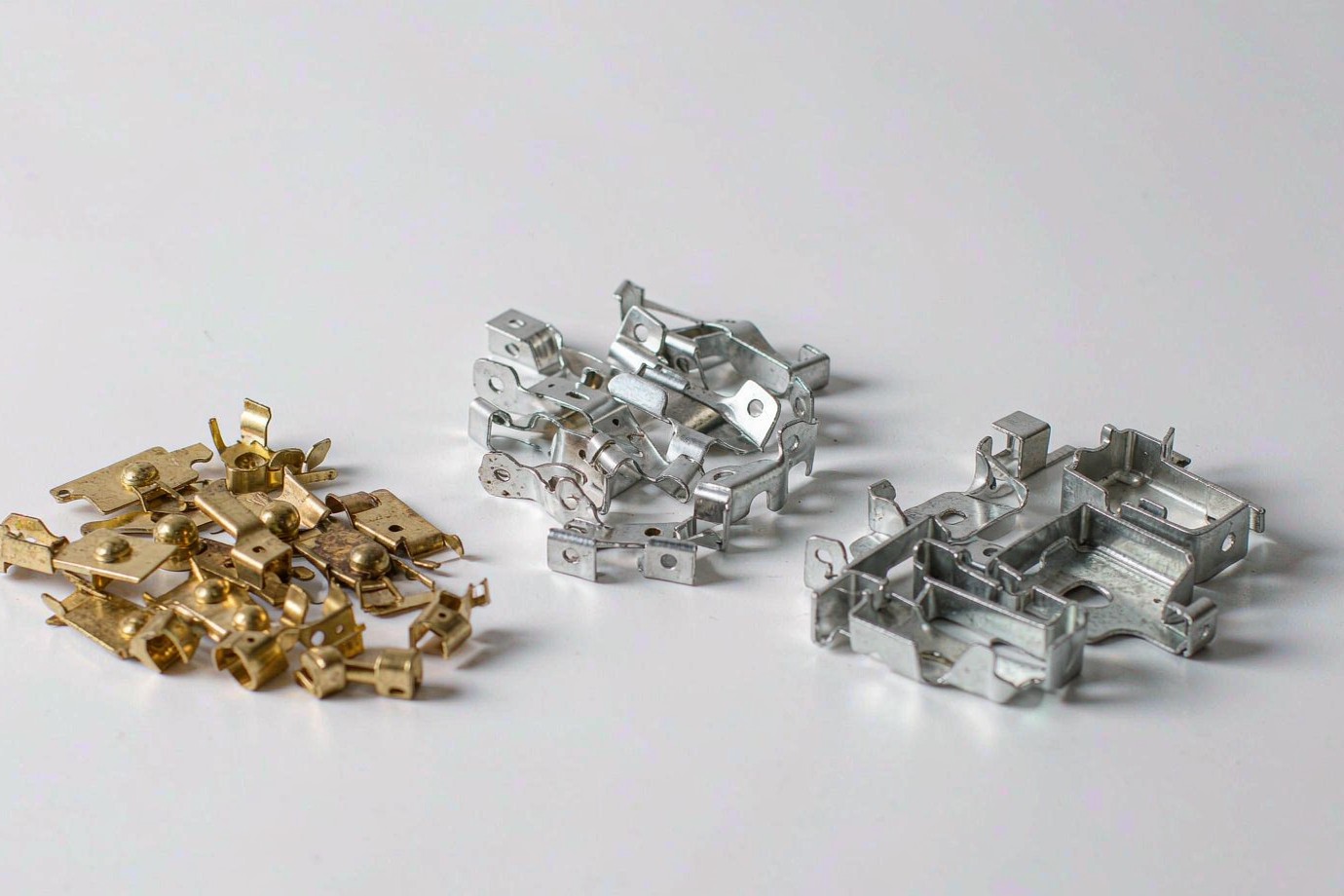
| Part types | Terminals, contact tabs, spring clips, brackets, retainers, shims, formed covers. |
| Forming routes | Single-operation, compound and progressive die stamping; laser cutting and bending where a die is not yet justified. |
| Tooling | Selected from part geometry and expected volume. Quoted as a separate line, not hidden in the unit price. |
| Secondary steps | CNC machining, tapping, deburring and finishing, combined where the drawing calls for them. |
| Inspection | First article, in-process and final inspection to an agreed control plan. |
| Quality system | ISO 9001:2015 certified. |
| Supply model | OEM/ODM build-to-print. Prototype from 1 piece. Founded in 1998. |
Quick Answer for Buyers
Custom stamped components are made from brass, stainless steel or aluminum sheet to your drawing. Brass suits electrical terminals and contacts, stainless steel suits spring clips and corrosion-resistant hardware, and aluminum suits lightweight brackets and formed covers. We select the die route from your part geometry and expected volume, combine secondary machining and finishing where needed, and verify dimensions against an agreed inspection plan before shipment.
What can you stamp?
Electrical terminals, contact tabs, spring clips, retainers, mounting brackets, shims, spacers, formed covers and support plates. If your part is not listed, send the drawing and we review it as a geometry, not as a category.
Which material should I choose?
Start from the job. Conductivity and contact surface point to brass; spring behaviour and corrosion exposure point to stainless steel; low weight and formed shapes point to aluminum. Grade and temper are then confirmed against the drawing.
How will you make it?
We choose between laser cutting and bending, a single-operation die, a compound die or a progressive die based on the features, the first order and the forecast volume. The route is agreed with you before tooling starts.
How do you prove quality and cost?
Tooling cost and unit price are quoted separately. Dimensions are checked against the drawing at first article, during production and before shipment, with the inspection documents agreed in the quotation.
Stamped Components We Make
Buyers usually arrive with a part name rather than a process. These are the part families we are asked to quote most often. The material column is a starting direction, not a fixed rule.
Terminals and connectors
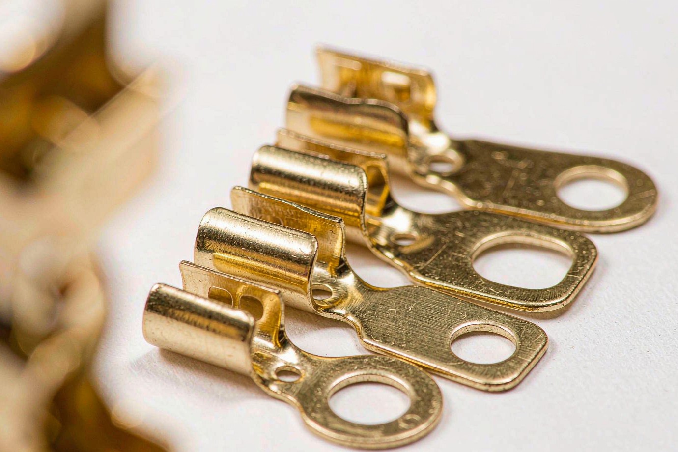
Crimp terminals, ring lugs, connector tabs. Usually brass. Contact face, plating and burr direction matter most.
Contact tabs and battery contacts
Flat contacts, spring tabs, grounding clips. Usually brass or a spring-grade stainless steel.
Spring clips and retainers
U-clips, retaining clips, spring plates. Usually 301 stainless where elastic behaviour is needed.
Mounting brackets and supports
L-brackets, angle brackets, support plates. Stainless steel for strength, aluminum where weight matters.
Shims, washers and spacers
Flat blanked parts where thickness, flatness and edge condition drive the fit.
Formed covers and housings
Shallow formed covers, shields and equipment panels. Usually aluminum or stainless steel.
Brass Stamping Parts
Brass stamping is used for custom electrical terminals, contact tabs, connector components and formed hardware where cold-forming behaviour, dimensional consistency and surface condition matter. The grade and temper are selected according to conductivity, strength, spring behaviour and forming geometry.
Brass is not one material. The grade, the temper and the plating all change how the part behaves, so we ask for them at the drawing stage rather than assume them.
| C26000 cartridge brass | Good cold-forming behaviour. Used for stamped terminals, contact tabs and connector parts. |
|---|---|
| C26800 brass | Used for specific formed and structural parts such as connecting strips and custom formed hardware. |
| Other copper alloys | Selected where conductivity, spring behaviour or a specified material calls for a different grade. |
- Alloy grade: state the grade on the drawing, not just the word brass.
- Temper: soft, half hard or hard conditions form differently and spring back differently.
- Conductivity: brass does not carry current as well as pure copper. If current load or contact resistance is critical, compare the actual copper alloy options against the requirement.
- Plating: nickel, tin or silver is chosen for the contact function and the assembly environment.
Stainless Steel Stamping Parts
Stainless steel stamping is used for retaining clips, mounting brackets, formed supports and corrosion-resistant hardware. Grade selection depends on corrosion exposure, strength, required spring properties, surface condition and forming geometry. Springback and work hardening are reviewed during tooling and process development.
| 301 stainless steel | Available in different hardness conditions. Considered for spring clips, spring plates and retainers. |
|---|---|
| 304 stainless steel | General corrosion resistance and forming behaviour. Used for brackets, washers and general hardware. |
| 316 / 316L stainless steel | Better resistance to chlorides. Considered for marine, chemical and outdoor hardware. |
- Springback: different grades and thicknesses spring back differently, so the die angle is developed during tryout.
- Work hardening: forming changes the local hardness; this affects any later forming or machining step.
- Edge quality: die clearance and punch condition drive the burr and the edge finish on cut features.
- Surface state: brushed, polished or passivated surfaces need to be specified before production release.
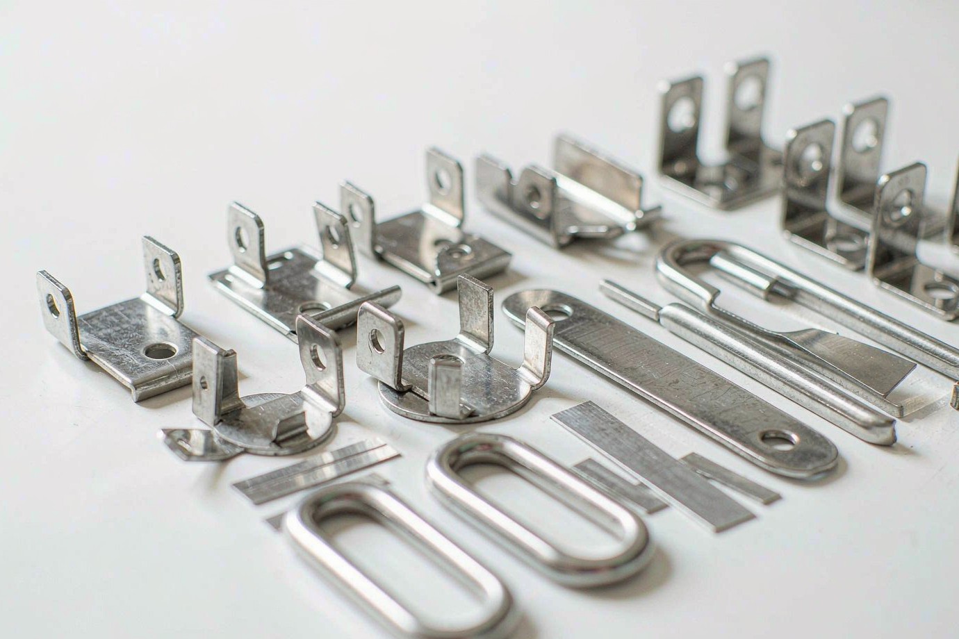
Aluminum Stamping Parts
Aluminum stamping provides lightweight formed components for industrial equipment, electrical housings and mounting assemblies. Alloy and temper selection should consider bend radius, grain direction, springback, strength requirements and subsequent finishing. 5052 is often considered for formed sheet components, while 6061-T6 needs closer review for demanding bends.
| 5052-H32 / H34 | Bent brackets, mounting plates and formed covers. Better forming behaviour makes it a common first choice. |
|---|---|
| 6061-T6 | Specific structural parts, machined parts and formed parts that have been reviewed. Higher strength, but bend radius and cracking risk need evaluation. |
| 3003 | Specific lightweight formed parts where forming behaviour is useful and the strength requirement can be met. |
- Bend radius: set it for the actual alloy, temper and thickness; one radius does not fit all materials.
- Grain direction: bending across the rolling direction can raise the cracking risk on harder tempers.
- Temper: state the temper at forming and at delivery, especially where heat treatment is involved.
- Surface protection: aluminum marks easily, so handling and protection during forming are part of the process plan.
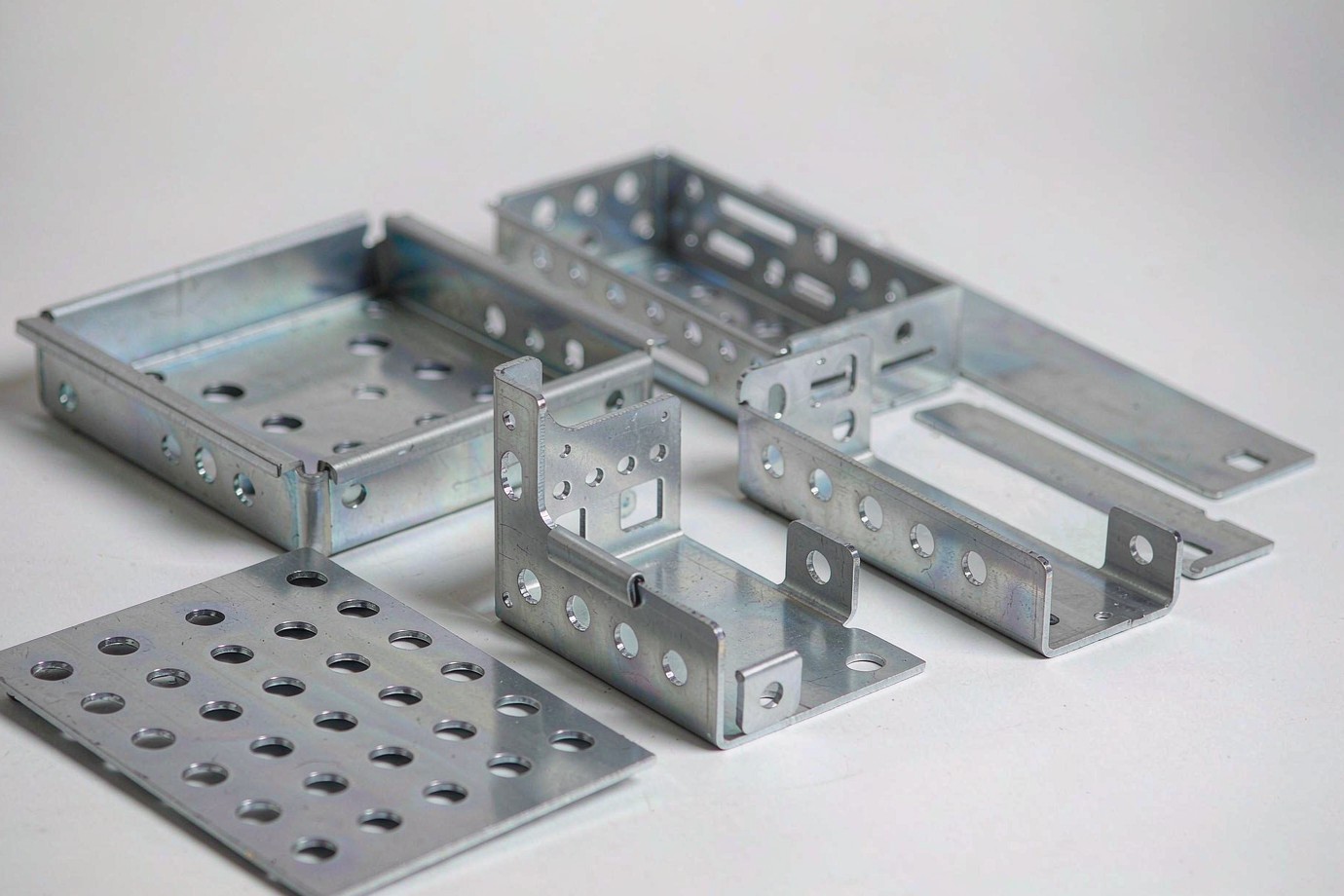
Choosing Between Brass, Stainless Steel and Aluminum
Material choice is a function of the part, not a ranking. The table shows the practical differences that affect the die, the process plan and the final inspection.
| Comparison | Brass | Stainless steel | Aluminum |
|---|---|---|---|
| Main advantage | Forming behaviour and contact surface | Strength, corrosion resistance, elastic grades | Low weight and formed shapes |
| Typical parts | Terminals, contact tabs, connectors | Spring clips, brackets, retainers | Support plates, brackets, covers |
| Key process | Piercing, bending, forming, plating | Blanking, forming, springback control | Blanking, bending, surface protection |
| Main risk | Temper choice, conductivity, burrs | Work hardening, springback, burrs | Cracking, springback, surface marks |
| Common finishing | Nickel, tin or silver plating | Passivation, polishing, brushing | Anodizing, powder coating |
For a wider reference on material families and where they fit, see our materials page.
Stamping Processes and Die Selection
Not every part should use the same die. The route is chosen from the features on the drawing and the volume you expect, then confirmed before tooling starts.
Single-operation die
One operation per stroke. Suited to simple parts, trials and lower volumes. Low initial tooling cost, more handling and re-positioning between steps.
Compound die
Several cutting operations such as piercing and blanking in one stroke at one station. Useful when feature-to-feature position matters on a flat part.
Progressive die
A strip passes through a series of stations. Each stroke adds a feature and a finished part leaves the last station. Suited to repeat volume where feed stability and die life matter.
Transfer and special routes
Considered where a part must move between stations or has a deeper three-dimensional form. Reviewed separately against material flow and forming depth before proposing.
| Order and part condition | Candidate route | Main consideration |
|---|---|---|
| Flat sample part, early trial | Laser cutting or a single-operation die | Initial investment before the design is stable |
| Simple piercing and blanking | Single-operation die | Number of operations and repeated positioning |
| Several linked cut features | Compound die | Positional relationship between features |
| Multi-station forming | Progressive die | Annual volume, press time and feed stability |
| Deep or three-dimensional form | Evaluated separately | Material flow, forming depth and die cost |
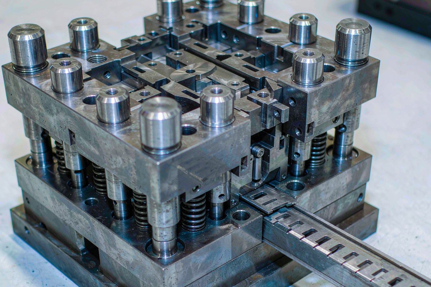
Press Capability and Manufacturing Envelope
A press tonnage number on its own does not tell a buyer whether a part can be made. What matters is how the press, the die, the strip and the inspection plan fit your specific drawing. This table shows what we confirm during the engineering review rather than a general promise.
| Press and equipment | Matched to the part after the drawing, material and die layout are reviewed. Confirmed at quotation. |
|---|---|
| Sheet thickness | Taken from your drawing. The workable range depends on grade, temper and part geometry. |
| Part size | Confirmed from the blank and strip layout, not assumed from a general maximum. |
| Strip feeding | Coil width, pitch and feed accuracy are set at the die design stage. |
| Tool route | Single-operation, compound or progressive, chosen from geometry and volume. |
| Secondary steps | Laser cutting, bending, CNC machining, tapping and deburring as the drawing requires. |
| Volume | Sample, low-volume and production quantities quoted as separate stages. |
| Documentation | Material certificate, dimensional report and other records as agreed in the quotation. |
We do not publish a universal press, thickness, tolerance or monthly output figure. Those numbers only carry meaning when they are tied to a specific part, material and die. Press capability, workable thickness and achievable tolerance are confirmed against your drawing during the engineering review, and the agreed values are written into the quotation and the inspection plan.

Design for Manufacture: Seven Checks Before Tooling
Most stamping problems are decided on the drawing, not on the press. These are the seven points we review with you before a die is built.
- Material definition: grade, temper, nominal thickness, thickness tolerance and grain direction where bending is involved.
- Hole size and spacing: very small holes weaken the punch; holes too close to each other or to an edge can distort the part and damage the die.
- Bend radius and springback: set by the actual alloy, temper, thickness and bend direction. One radius does not fit every material.
- Burr direction and edge quality: state which face the burr is allowed on, the permitted burr height, and any sharp-edge or safety requirement.
- Grain direction: bending with an unsuitable rolling direction raises the cracking risk on harder tempers.
- Hole-to-bend distance: holes close to a bend line can change shape or move after forming, which affects assembly fit.
- Finishing allowance: plating, anodizing, powder coating, passivation and polishing change mating holes, contact faces and final dimensions. Define masked areas and final acceptance dimensions early.
Secondary Operations and Integrated Processing
Stamped parts often need one more step before they can be assembled. Because we work across several processes, those steps can be planned as one project instead of being sourced separately.
| Customer need | Possible combination | Value to the project |
|---|---|---|
| New part sample, design not yet fixed | Laser cutting + bending | Avoids early dedicated tooling cost |
| Repeat stamped part at volume | Progressive die + deburring | Stable, repeatable production |
| Tight hole position on a key feature | Stamping + CNC drilling or milling | Critical features finished after forming |
| Threaded assembly interface | Stamping + tapping | Part arrives ready to assemble |
| Multi-step metal bracket | Laser cutting + stamping + bending | Combined geometry in one project |
| Specified appearance or protection | Stamping + surface finishing | Function and finish handled together |
All six core processes — CNC machining, injection molding, mold making, 3D printing, die casting and sheet metal fabrication — are performed in-house under one ISO 9001:2015 quality system. See our CNC machining services and sheet metal fabrication services pages for the wider capability.
Not every stamped part needs secondary machining. Which steps your part needs is decided during the engineering review and stated in the quotation. We do not add operations the drawing does not call for, and we do not present every listed combination as a standard package applied to all parts.
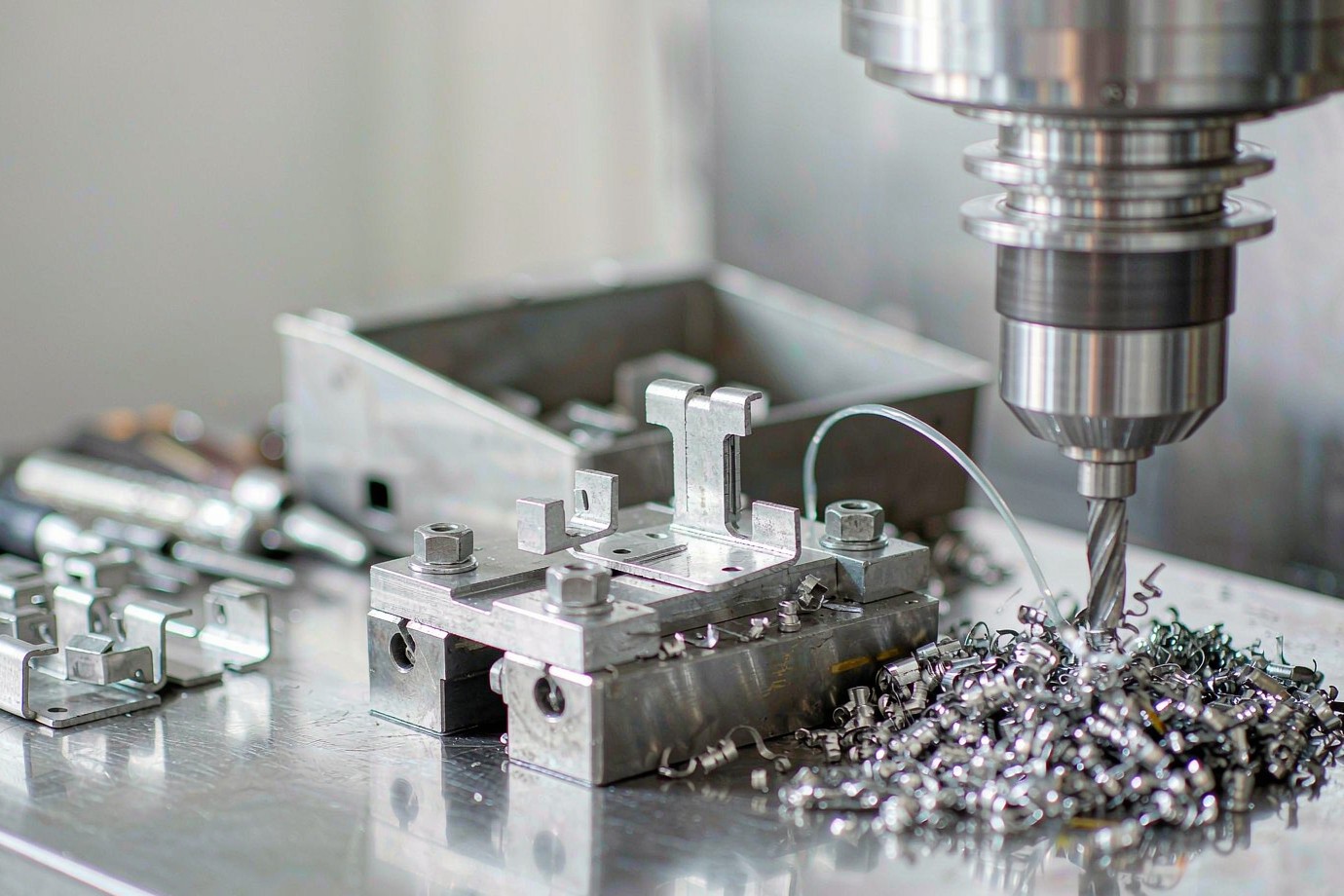
Surface Finishing by Material
Finishing is a selection problem, not a list of options. The right finish depends on the material, the contact function and the environment the part will see.
| Finish | Typical use | What to specify |
|---|---|---|
| Nickel plating | Brass connectors, mechanical metal parts | Coating thickness, corrosion requirement, mating fit |
| Tin plating | Electrical terminals | Solderability, contact behaviour, coating quality |
| Silver plating | Specific electrical contacts | Contact resistance and surface state |
| Passivation | Stainless steel parts | Process route and any specified corrosion test |
| Brushing, polishing, electropolishing | Stainless steel appearance parts | Surface finish level and cleaning requirement |
| Anodizing | Aluminum parts | Coating type, colour, corrosion need, dimensional change |
| Powder coating | Structural brackets and visible parts | Coating thickness, adhesion and masked areas |
Quality Control and Inspection
Stamping quality is built into the die, the material and the control plan. Inspection confirms it; inspection alone cannot create it. These five activities are kept separate and agreed before production release.
- Raw material verification: grade, thickness, material certificate, batch traceability, and temper or mechanical property where applicable.
- First article inspection: main dimensions, hole position and spacing, bend angle and height, key profile, burr direction and height, surface condition.
- In-process control: key features checked against the agreed control plan, with attention to die wear, strip feeding, punch and die condition, material batch changes, springback and burr height.
- Final inspection: dimensions, appearance and the agreed documents checked before shipment.
- Quality documentation: issued according to the order and the agreed plan, not as a blanket package.
| Check | Typical method |
|---|---|
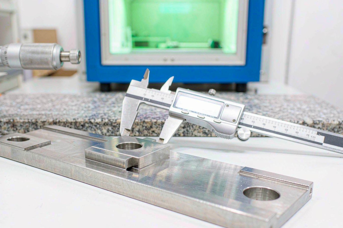
| Size and profile | Caliper, micrometer, optical comparator |
| Hole position and spacing | Vision measurement or coordinate measurement where specified |
| Material thickness | Thickness gauge or micrometer |
| Burr height | Agreed burr measurement method or suitable optical measurement |
| Surface finish | Roughness tester or a specified visual standard |
| Hardness | Hardness tester where the drawing calls for it |
| Corrosion behaviour | Only where the customer specifies the method, duration and acceptance criteria |
| Document | When it applies |
|---|---|
| Material certificate | By order and material requirement |
| Dimensional inspection report | First article or a specified batch |
| First article inspection record | New part or when the customer requires it |
| Process control records | By the agreed quality plan for the project |
| Surface treatment report | Where a finish and its checks are specified |
| Material compliance declarations | By end-product application and customer requirement |
First article inspection, in-process inspection, sampling inspection and final inspection are separate activities. We describe the actual plan for the order instead of using a single general phrase, and we only call a check a full inspection where a full inspection is really carried out. A salt spray or other corrosion test is performed only when the customer specifies the test method, duration and acceptance criteria; a dimensional report is not a substitute for a corrosion test.
Who Sources These Parts
The same material can serve different buyers for different reasons. These are the groups that most often send us a stamped-part drawing.
Electrical and electronics makers
Terminals, contacts, grounding clips. Focus on conductivity, contact face, plating and burr control.
Automotive component suppliers
Mounting brackets, spring clips, retainers. Focus on material specification, dimensional stability and agreed process documents.
Industrial equipment makers
Support plates, brackets, formed parts. Focus on strength, weight, hole position and assembly fit.
HVAC and appliance makers
Clips, retaining plates, mounting hardware. Focus on cost, thickness, finishing and repeat supply.
Marine and outdoor equipment makers
Stainless brackets and formed components. Focus on chloride exposure, grade and surface state.
Contract manufacturers
Buyers folding a stamped part into a larger assembly who need it built to a controlled drawing and inspection plan.
From Sample to Repeat Orders
Tooling and production are separate stages. Keeping them separate is what lets a buyer review a sample before committing to a die.
Requirement review
Drawing, grade, temper, thickness, volume, finish and documents.
DFM and material review
Bends, holes, burr direction, grain direction and finishing allowance.
Route and quotation
Die route, tooling cost and unit price quoted as separate lines.
Tool build and tryout
Build the die, run tryout, adjust forming and feed conditions.
First article approval
Measure the sample against the drawing and agree the control plan.
Production and repeat orders
Run, inspect, ship, and maintain the tool and revision record.
What to Send for a Quote
The more of this you can supply, the more useful the first review will be. If some points are still open, send what you have and mark the open ones; we will tell you what else is needed before tooling.
| 2D drawing or 3D model | STEP, IGES, DWG or PDF with dimensions |
|---|---|
| Material grade and temper | For example C26000, 304 or 5052-H32, or the requirement to be met |
| Nominal thickness | From the drawing, with thickness tolerance where specified |
| Critical dimensions | Hole positions, bend angles, formed heights, flatness |
| Burr direction and edges | Which face, permitted burr height, sharp-edge requirements |
| Surface treatment | Plating, anodizing, passivation, plus masked areas |
| Quantities | Sample quantity, first order and expected annual volume |
| Revision plan | Expected repeat orders and possible design changes |
| Inspection documents | Dimensional report, material certificate or other records needed |
| Application | Where the part is used and what it mates with |
FAQ
What materials can be used for custom metal stamping?
Can you make stamped parts from our drawings?
What is the best material for stamped electrical terminals?
Is 5052 or 6061-T6 better for stamped aluminum brackets?
What is the difference between progressive and compound die stamping?
How do you decide which die to use for an order?
What tolerances can be held on stamped parts?
How are burrs and edge quality controlled?
Can stamped parts be plated or anodized?
What is the minimum order quantity for custom stamping?
What information is needed for a metal stamping quote?
How do you verify quality on repeat orders?
Ready to review your stamped part?
Send the drawing, the material and the volume you expect. We will return an engineering review, a die route recommendation and a tooling-and-unit-cost estimate scoped to your part, not a general figure.
Request a Custom Quote Explore all metal stamping servicesXiamen Goldcattle Plastic & Metal Products Co., Ltd. — Founded in 1998 · ISO 9001:2015 certified · OEM/ODM build-to-print.