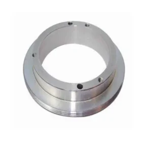
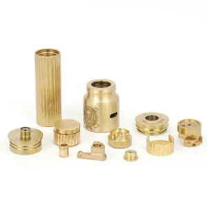
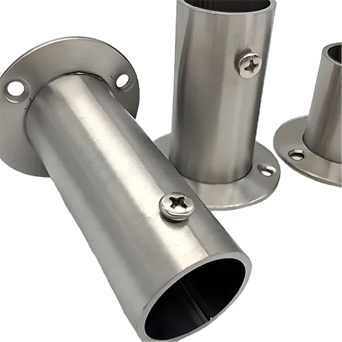
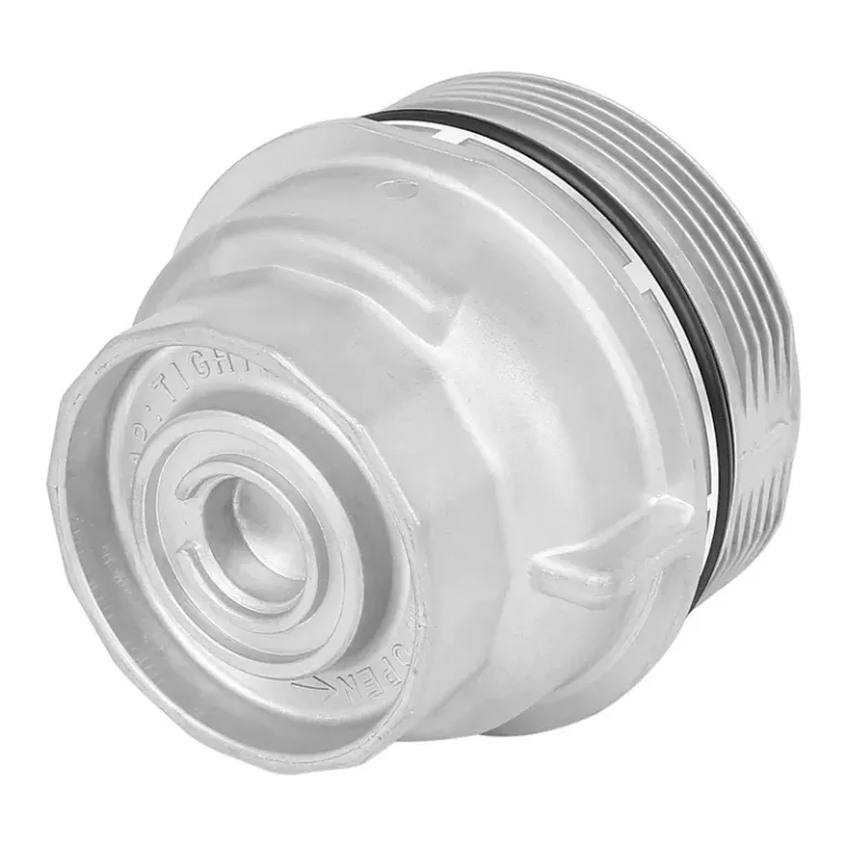
Aviation Aluminum 5-Axis CNC Machining | ±0.005mm
Place of Origin: Fujian, China
Type: Broaching, DRILLING, Etching / Chemical Machining, Laser Machining, Milling, Other Machining Services, Turning, Wire EDM, Rapid Prototyping
Micro Machining or Not: Micro Machining
Model Number: CMP-16
Brand Name: JSD
Product name: 5 axis cnc machining parts
Material: Aluminum/stainless steel/brass, etc.
Process: Cnc Machining
CNC Machining or Not: CNC Machining Turning Parts
Equipment: CNC Machining Centres
Surface treatment: Customer’s Request
Service: Customized OEM
Application: Industrial Equipment
Tolerance: +/-0.005mm
MOQ: 1
Description
Custom CNC machined component · Model CMP-16
Custom 5-Axis CNC Machined Aerospace Aluminum Parts
Aerospace aluminum components machined from your drawings, 3D CAD files or reference samples — built for complex, multi-sided parts that need controlled dimensions, lightweight construction and application-specific finishing.
Prototype · Low volume · Repeat production — quoting from CAD, drawing or sample *
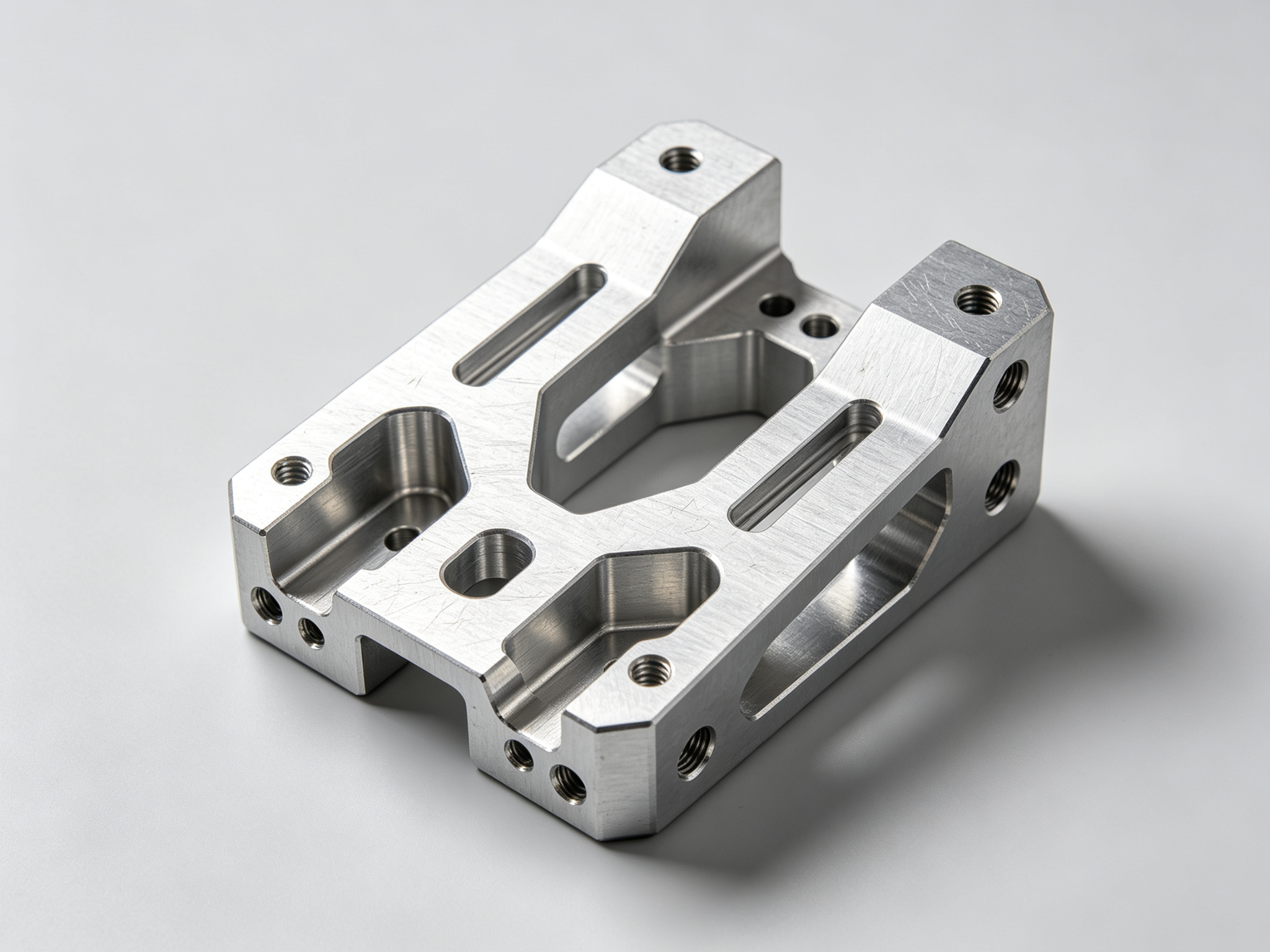
01 / product overview
One part identity: aerospace aluminum, 5-axis machined, made to your drawing
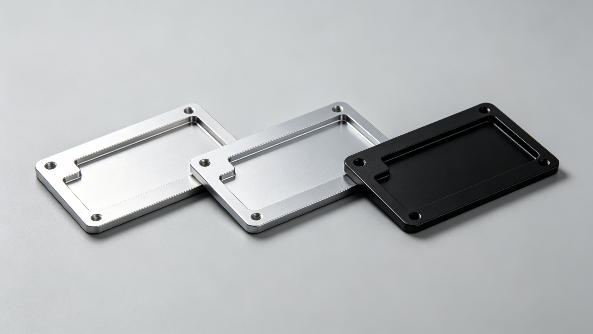
This custom CNC machined aerospace component is manufactured from customer-specified aluminum alloy using multi-axis CNC machining. The 5-axis process suits complex geometries with multiple machined faces, angled features, pockets and contoured surfaces that would otherwise require repeated reorientation on conventional 3-axis equipment.
Material grade and temper are selected according to the engineering drawing or purchasing specification. Where required, surface finishing and dimensional inspection are completed according to the agreed production documentation.
02 / why 5-axis for this part
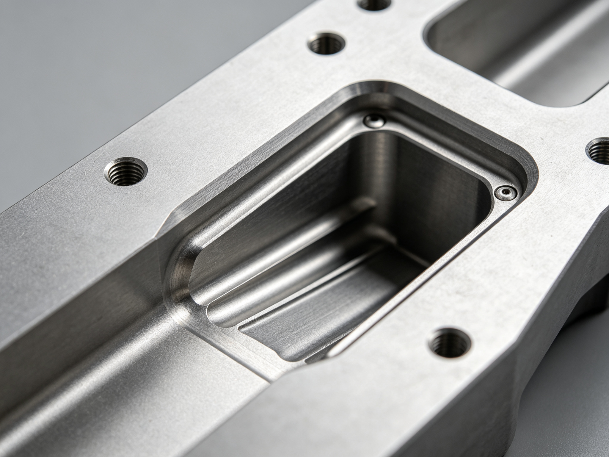
This geometry is why the part needs 5-axis machining
Not a general lesson in CNC. The reasons below are specific to the features on this product family.
Multiple machined faces are reached in fewer setups, so orientation errors between faces stay small.
Inclined holes, angled pockets and compound surfaces are machined in the part's natural orientation instead of with angled fixtures.
Fewer clamp → machine → unclamp → reposition → re-clamp cycles mean less risk of distortion and datum shift.
The value is in the position of holes, datums and mounting faces relative to each other, not just a single dimension.
Schematic — typical features of this product family; not a specific customer drawing.
03 / material specification
Exact alloy and temper, matched to the drawing
The product is defined by a specific alloy and temper, not a general material list. The primary option is stated here; alternatives are listed only as available options.
Primary material
High-strength aluminum alloy for parts that need a high strength-to-weight ratio, supplied to the applicable material specification. SAE AMS4078 covers 7075 T73 sheet / T7351 plate where specified. Final alloy, temper and specification follow the approved engineering drawing or purchasing specification.
Material traceability
For projects requiring aerospace material control, material documentation can be provided according to the purchase specification and project requirements:
- Alloy designation
- Temper
- Heat / lot
- Material certificate
- Source documentation
- Part identification where required
| Alloy | Typical engineering consideration |
|---|---|
| 6061-T6 | General-purpose structural and machined aluminum |
| 7075-T6 / T651 | High-strength applications |
| 7075-T7351 | Overaged temper with improved stress-corrosion resistance; applicable plate applications |
| 2024-T3 | Applications emphasizing fatigue performance and aerospace usage |
| 7050 | High-strength structural applications where specified |
04 / design considerations
Guidance for 5-axis aluminum part design
What we review before quoting, so your drawing machines cleanly the first time.
Thin walls
Very thin walls can deform from cutting forces, residual stress and fixturing conditions. Minimum wall thickness is evaluated against alloy, geometry and part size rather than one universal value.
Deep pockets
Deep pockets require tool reach, rigidity, chip evacuation and tool diameter to be considered together with the pocket's depth-to-width ratio.
Small holes
Hole diameter, depth-to-diameter ratio, material, drilling strategy and tolerance interact — small deep holes need the right tooling and sequence.
Radii & internal corners
Small internal radii constrain tool diameter, add machining time and increase tool wear. Generous radii where the design allows keep cost down.
Datums & GD&T
Critical dimensions should relate to clear datums and inspection references, so the part can be measured and verified consistently.
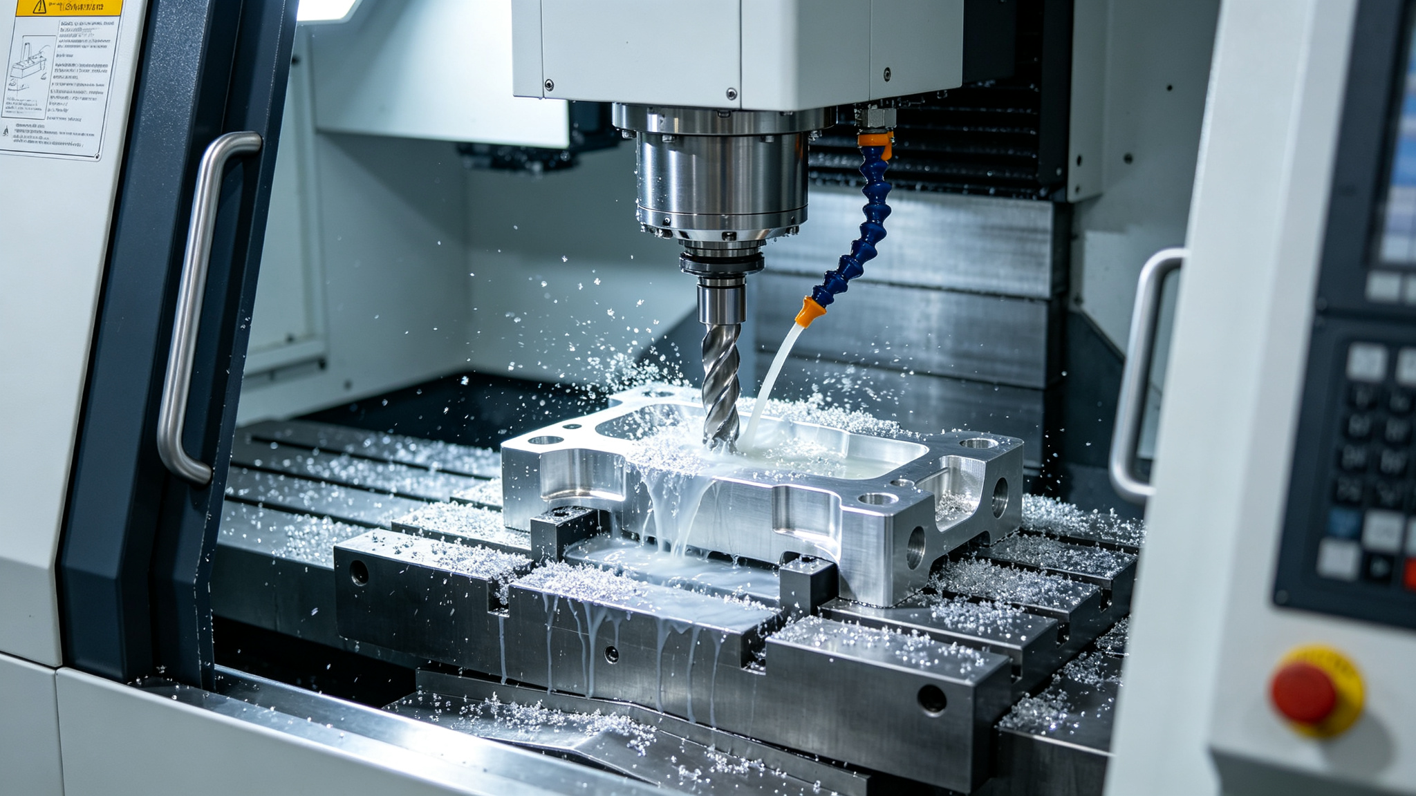
05 / from cad file to finished part
A defined path from your file to a shipped component
Drawing / CAD review
Material, tolerance, GD&T, surface finish and quantity checked against the file.
DFM review
Tool access, thin walls, deep pockets, fixturing and machining sequence reviewed.
CAM programming
Tool orientation, roughing, semi-finishing and finishing planned for the geometry.
5-axis machining
Simultaneous multi-axis milling on CNC machining centres.
Surface treatment
Anodizing, conversion coating or other specified finish applied.
Inspection
Dimensional, GD&T and CMM checks per the agreed inspection plan.
Documentation & packaging
Reports and protective packaging prepared for dispatch.
DFM comments are returned before machining begins, so you know what affects cost and lead time before production starts.
06 / quality & inspection
How precision is verified, not just promised
Dimensional inspection
Critical dimensions, hole diameters, thickness and mounting interfaces checked against the drawing.
GD&T inspection
Position, flatness, profile, perpendicularity and concentricity per drawing / GD&T requirements.
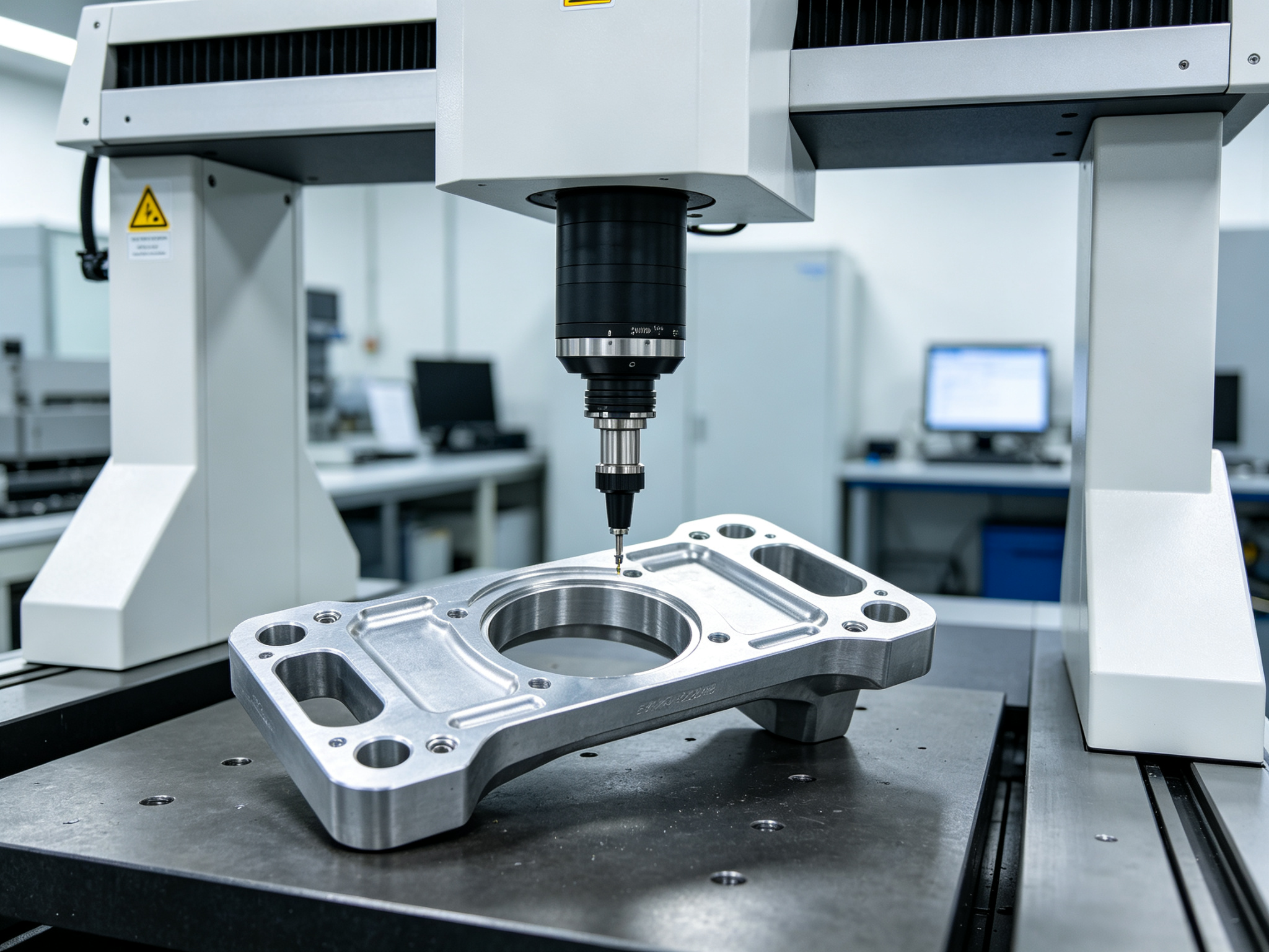
CMM measurement
CMM can be used for critical dimensional verification of complex 5-axis geometry where required.
Visual inspection
Burrs, scratches, dents, machining marks and surface-treatment defects checked before dispatch.
First article inspection
FAI documentation can be prepared for projects requiring aerospace-style FAI, executed per AS9102C requirements where the project scope requires it.
Documentation
Material certificates, dimensional reports, FAI and other customer-specific documents as agreed.
What you can receive
- Material certificate
- Dimensional inspection report
- CMM report where required
- FAI documentation as agreed
- Photographic record of key features
07 / surface finishing
Finishing options defined by purpose
Finish selection and any applicable specification follow the approved drawing and production documentation.
| Finish | Typical purpose |
|---|---|
| Clear anodizing | Corrosion protection / appearance |
| Hardcoat anodizing | Wear resistance / surface hardness |
| Color anodizing | Appearance and corrosion protection |
| Chemical conversion coating | Corrosion protection; electrical applications where specified |
| Bead blasting | Uniform matte appearance |
| Polishing | Appearance / specified surface finish |
| Custom finish | According to drawing |
08 / typical part applications
Where this product family is used
The intended application on your drawing defines the requirements; this list reflects typical use of the product family.
Aerospace structural components
- Brackets
- Mounting components
- Structural plates
- Housings
UAV / drone components
- Frames
- Motor mounts
- Sensor mounts
- Structural interfaces
Aerospace equipment
- Instrument housings
- Equipment brackets
- Precision fixtures
- Mounting components
09 / who buys this product
Built for engineering procurement
Aerospace engineering teams
- Material specification
- Dimensional control
- Documentation
UAV / drone developers
- Weight
- Structural rigidity
- Repeatability
Aircraft equipment manufacturers
- Fit
- Interface dimensions
- Repeat production
High-performance equipment
- Material control
- Documentation
- Production consistency
10 / project profile
What a completed project looks like
Representative example — final values follow the approved drawing and project record. Completed project records can be shared under NDA on request.
11 / request a quote
What we need to quote your part
A complete RFQ lets our engineering team review material, machining approach, tolerances and finishing requirements before quotation.
STEP / STP / IGES / X_T or another neutral format.
Tolerances, GD&T, material specification and surface finish.
Prototype, low volume or recurring order.
For example 7075-T7351 / AMS4078, or per your drawing.
Anodizing, conversion coating or other specified finish.
For shipping cost and lead-time planning.
Material certificate, dimensional report, FAI or other customer-specific documents.
Ready to quote your custom part?
Send your 3D CAD file, 2D drawing and quantity. Our engineering team reviews material, machining approach, tolerances and finishing before quotation.
- Free DFM analysis of your design
- Fast quote response within 24 hours
- Free design & manufacturing consultation
12 / frequently asked questions
Straight answers for engineering buyers
What aluminum alloys can be used for aerospace CNC parts?
What is 7075-T7351 aluminum used for?
Why is 5-axis machining used for aerospace aluminum parts?
Can you machine parts from our CAD drawing?
Can you provide material certificates?
Can you provide CMM reports?
Can you support FAI documentation?
What tolerances can you achieve?
What surface finishes are available?
Can you produce one prototype?
What affects the cost of a 5-axis aerospace aluminum part?
What information is required for quotation?
Ready to quote your custom part?
Upload your 3D CAD file, 2D drawing or reference dimensions. Our engineering team reviews material, machining approach, tolerances and finishing requirements before quotation.