

Large Precision CNC Parts | ±0.05mm, Base Plates
Material Capabilities : Aluminum, Brass, Bronze, Copper, Hardened Metals, Precious Metals, Stainless steel, Steel Alloys
Type : Broaching, DRILLING, Etching / Chemical Machining, Laser Machining, Milling, Other Machining Services, Turning, Wire EDM, Rapid Prototyping
Micro Machining or Not : Micro Machining
Model Number : OEM/ODM
Brand Name : JSD
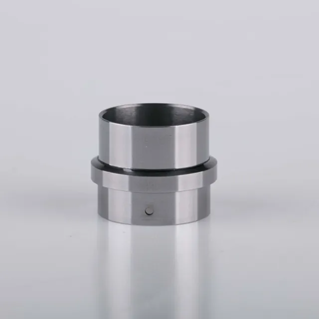
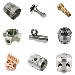
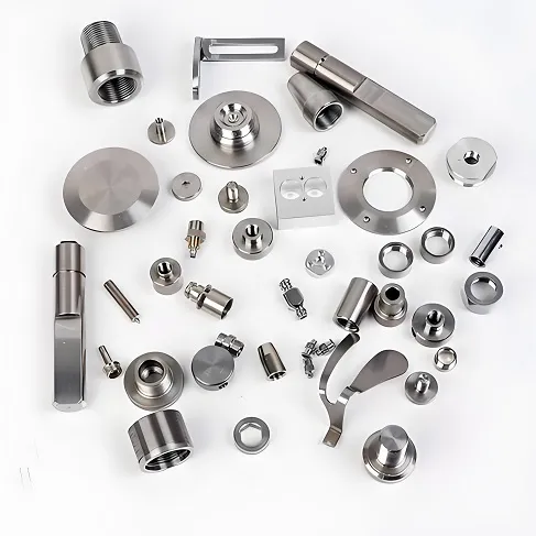
Product name : CNC milling and turning parts
Surface treatment : Brushing/Polishing/Lacquer etc.
Service : Customized OEM
Size : Customized Size
Color : Customized Color
Tolerance : +/-0.05mm
Main Prosess : Precision Cnc Micro Machining
MOQ : Small Orders Accepted
Certification : ISO9001
QC Control : 100% Inspecttion
Description
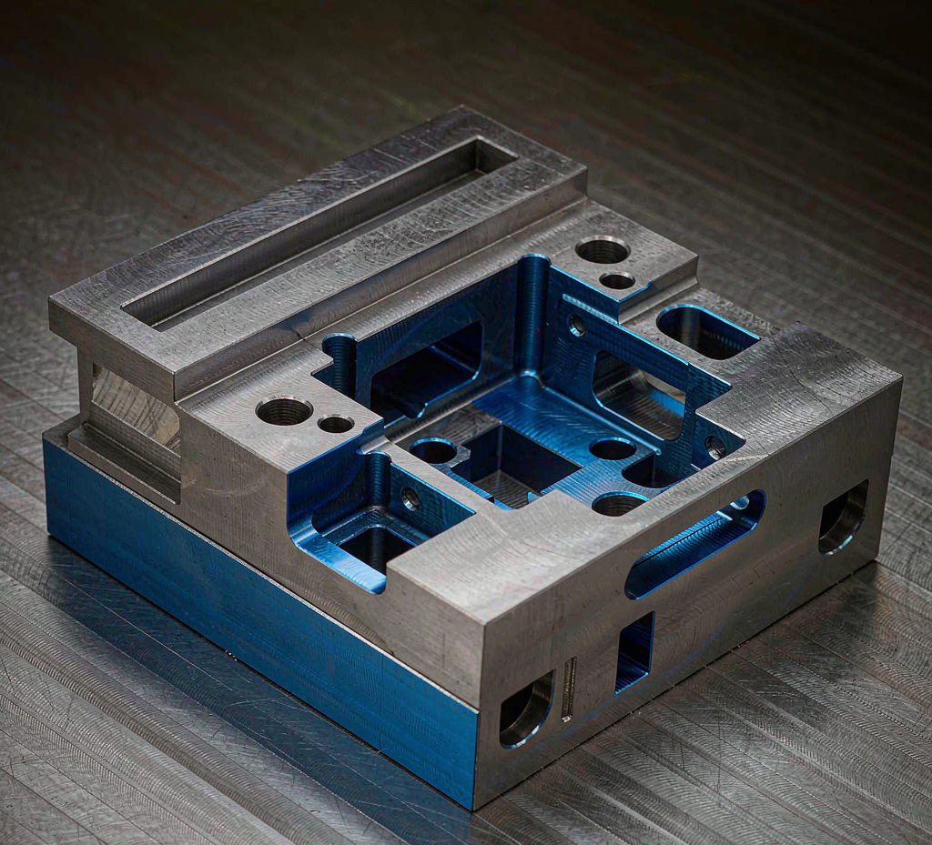
Large-Part CNC Machining
Custom CNC Machining for Large Mechanical Components
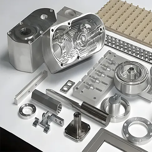
Goldcattle machines drawing-based large mechanical components — base plates, housings, structural parts, shafts and flanges. Each project is reviewed for part size, material, critical tolerances, workholding and inspection before any commitment, so your large part is planned, not guessed.
What large mechanical parts can we machine?
Large-part machining is defined less by a single dimension than by how the workpiece is supported, located and measured. The right process depends on the component's envelope, weight, material and the features that actually control your assembly.
Base & mounting plates
Flat plates with locating holes, pockets and reference surfaces for equipment and automation frames.
Equipment housings
Large enclosures and bodies with bores, flanges and mating interfaces for industrial machinery.
Structural components
Brackets, frames and load-bearing parts where flatness, parallelism and datum control matter.
Shafts & rolls
Long turned parts evaluated for diameter, length, weight and support during turning.
Flanges & discs
Large-diameter circular parts with bolt circles, faces and sealing surfaces.
Custom fixtures
Jigs and fixture bodies built to hold your part or tooling with repeatable accuracy.
A part type is accepted only after we confirm it against available machines, workholding and inspection. If a feature needs a process outside our scope, we say so during the review.
Large-format CNC milling, turning and boring
Milling
The practical work envelope is assessed against the part's length, width, height and setup orientation. Features on multiple faces are planned as sequenced setups with datum transfer, not assumed from one clamping.
Turning
Maximum diameter, length, weight and workholding are evaluated separately from milling. Long or heavy parts are reviewed for steadyrest support and deflection control.
Boring & large holes
Bores, counterbores and large-diameter holes are planned for positional accuracy and surface finish relative to the part datum.
Drilling, tapping & multi-face
Hole patterns, threads and features across several faces are mapped to setups so positional tolerance is held through datum control.
We confirm the achievable envelope against your drawing during engineering review rather than publishing a single fixed travel number that may not reflect fixture and support limits.
Tolerances, flatness and geometric accuracy
| Requirement | How it is handled |
|---|---|
| General CNC tolerance | ±0.01 mm typical on standard features |
| Qualified critical features | ±0.005 mm where the feature and process are qualified |
| Flatness & parallelism | Specified per drawing; supported by staged machining and measured against datum |
| Hole patterns & position | Controlled through datum scheme and setup sequence |
| Surface finish | Matched to the functional face (sealing, bearing, reference) |
Tighter local limits are possible on qualified features, but are confirmed through engineering review rather than assumed to apply uniformly across a large component.
Workholding, datum control and distortion management
- Support & clamping plan — locations chosen to avoid deflection and movement under cutting loads.
- Datum transfer — reference features are established and carried across setups to keep position and orientation.
- Stress & distortion control — staged roughing, intermediate relief or finish-after-stress steps where geometry warrants.
- Access & clearance — tool reach and fixture bulk are checked so every critical feature is actually machinable.
The plan is set per part and material; we explain the approach in the review so you know how accuracy is protected before production.
Inspection and dimensional verification for large parts
Incoming material verification
Material grade, stock form and documentation are confirmed against the order before machining begins.
Process control
Setup, datum and critical-feature checks during production catch variation before it becomes scrap.
Critical-dimension inspection
Key sizes, hole positions, flatness and parallelism are measured against the drawing datum.
Documentation on request
Dimension reports, first-article inspection and material certificates are provided as agreed per order.
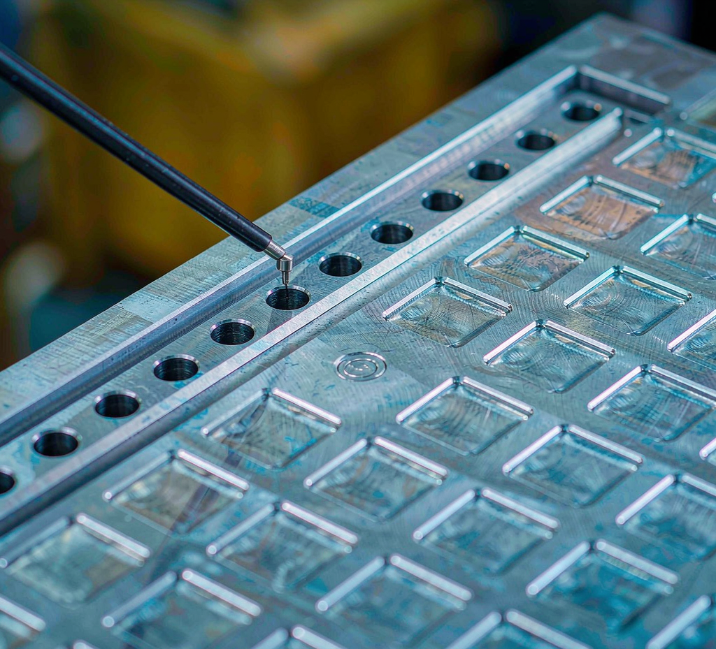
Measurement method is matched to feature size and accuracy — a CMM alone does not imply every large part is fully measured in one setup.
Lead time, packaging and shipping
| Stage | Typical window |
|---|---|
| Prototype | 3–7 working days |
| Low volume | 7–20 working days |
| Mass production | 15–25 working days |
Windows are confirmed per project after engineering review and depend on material availability, order quantity and any outsourced finishing. Packaging dimensions, weight and handling limits are agreed during quotation so shipping is arranged with the part, not after it is made.
What we need for your large-part quote
- 3D CAD file (STEP / IGES / STL) and 2D drawing (DWG / DXF / PDF) with tolerances.
- Overall dimensions and estimated part or blank weight.
- Material grade and stock form (plate, bar, casting, forging, welded blank).
- Critical features, datum references and geometric tolerances.
- Surface finish, coating or heat-treatment requirements.
- Prototype quantity, per-batch quantity and expected annual demand.
- Required inspection reports, material documents and target delivery date.
- Destination, packaging size and weight limits or handling restrictions.
Have a large part that needs machining?
Send your drawing and dimensions — our engineers review size, material, critical tolerances and inspection, then return a transparent quote, typically within 24 hours.
Submit your drawing → Get a quoteFrequently asked questions
What is the maximum part size you can CNC machine?
The maximum machinable size depends on the selected machine, process, setup orientation and workholding. Milling and turning limits are evaluated separately against your drawing; we confirm feasibility during engineering review rather than quoting a single fixed envelope.
Can large CNC-machined parts hold tight tolerances?
Critical features can be held to tighter limits than overall dimensions. We work to ±0.01 mm typical and ±0.005 mm on qualified features, with tolerance confirmed per drawing and feature through engineering review.
How is distortion controlled on large parts?
The machining plan accounts for stock condition, material stress, support and clamping locations, and the roughing and finishing sequence; stress-relief or staged machining is used where the geometry warrants. The strategy is set per part and material.
How are large machined parts inspected?
Critical dimensions, hole patterns, flatness, parallelism and datum features are checked against the drawing. Inspection uses CMM, gauges or portable measurement sized to the feature and part; for parts beyond a single CMM envelope, segmented or staged measurement is planned.
What materials and stock forms can you machine?
We machine metals to your specified grade and stock form — plate, bar, casting, forging or welded blank. Material availability and documentation requirements are confirmed during quotation review.
What do you need for a large-part CNC quote?
A 3D model or dimensioned drawing with tolerances, overall dimensions and estimated weight, material and stock form, critical features and datums, finishing needs, quantity and target delivery, plus any inspection or packaging requirements.
What are your lead times and minimum order quantity?
Prototypes start at MOQ 1 piece. Typical lead times are 3–7 working days for prototypes, 7–20 for low-volume and 15–25 for mass production, confirmed per project after engineering review.
Do you provide inspection reports and material certificates?
Dimensional reports, first-article inspection and material certificates are available on request, scoped to your order requirements. Certificate copies can be provided under NDA.