5-Axis CNC Machining | Stainless & Aluminum
| Attribute | Details |
|---|---|
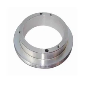
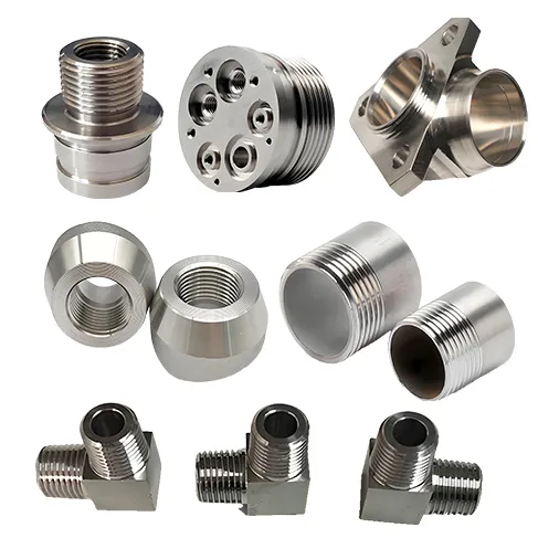
| Product Name | 5-Axis CNC Machined Custom Metal Parts |
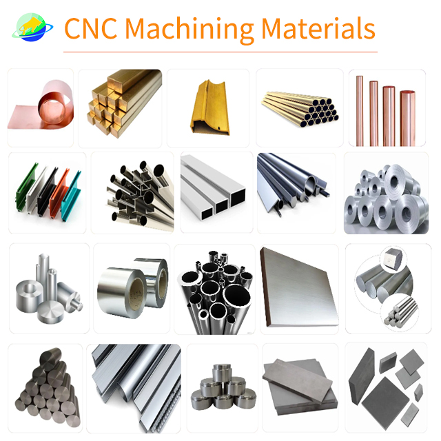
| Core Materials | Stainless Steel (304/316L), Aluminum Alloy (6061/7075), Brass, Copper, Titanium Alloy, Engineering Plastics (PEEK/ABS, etc.) |
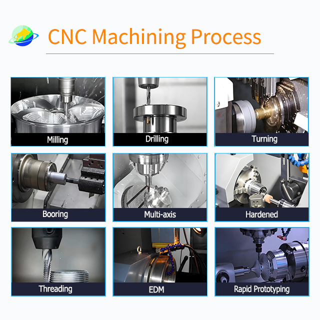
| Machining Processes | 5-Axis CNC Milling/Turning/Drilling/Tapping, Wire EDM, Rapid Prototyping |
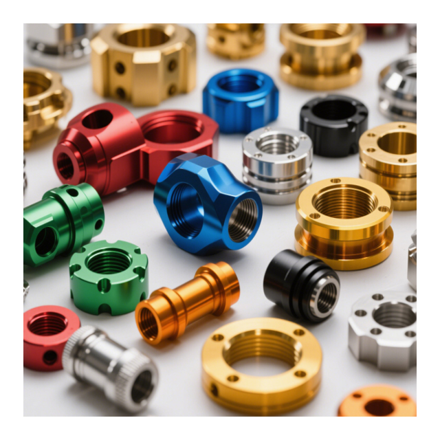
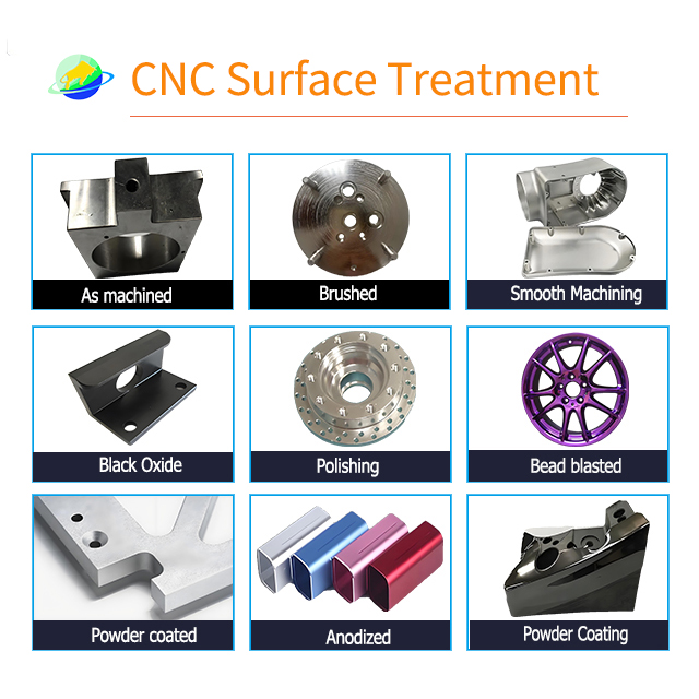
| Surface Treatments | Anodizing, Electroplating, Powder Coating, Polishing, Sandblasting, Black Oxide, Passivation, etc. |
| Machining Precision | Dimensional tolerance: ±0.005mm, Special areas: ±0.002mm |
| Certifications | ISO 9001, RoHS |
| Minimum Order Quantity (MOQ) | 1 piece |
| Packaging | Carton, Wooden Case, Pallet (Custom packaging available) |
| Lead Time | Samples: 1–7 days, Bulk orders: 1–30 days (Negotiable for >500 pieces) |
| Service Scope | OEM/ODM Customization, Drawing-Based Processing (Supports DWG/STEP/IGS, etc.) |
| Application Areas | Automotive, Aerospace, Medical Devices, Electronics, Mechanical Engineering, etc. |
| Origin | Fujian, China |
| Brand | JSD |
Description
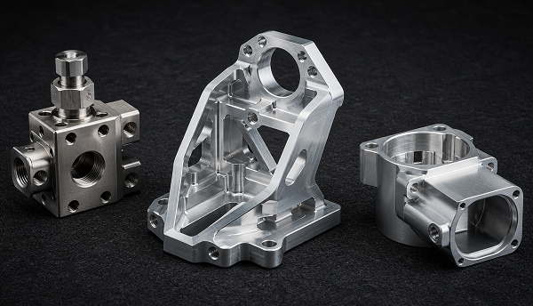
Custom 5-Axis CNC Machined Parts in Aluminum & Stainless Steel
Machine complex multi-face metal components in fewer setups, with controlled access to angled features, deep surfaces and critical interfaces.
*Subject to part geometry and capability review
Product Snapshot
| Product Type | Custom 5-axis CNC machined metal parts |
|---|---|
| Main Materials | Aluminum / Stainless Steel |
| Processes | 5-axis milling / multi-axis machining |
| Part Geometry | Multi-face / complex contours / angled features |
| Production | Prototype / small batch / repeat production |
| Tolerance | Drawing-defined; selected features subject to capability review |
| Finishes | Anodizing / passivation / blasting / polishing / coating* |
| Inspection | Dimensional inspection / CMM* |
| Input | 3D CAD + 2D drawing |
*Finish and inspection capabilities subject to part geometry and material. Usable machining envelope depends on fixturing, tool length, rotary orientation and collision clearance — not machine travel alone.
Why Use 5-Axis CNC Machining?
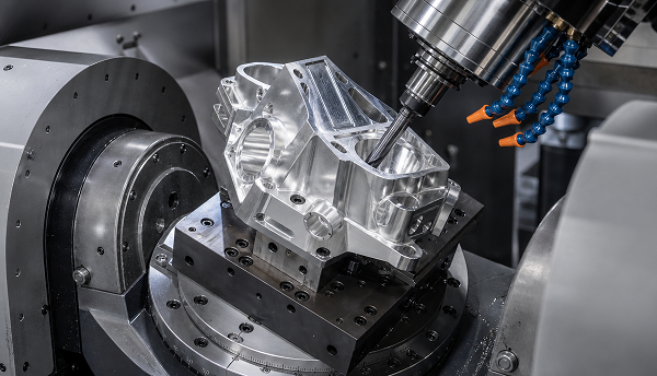
5-axis machining is not universally "better" — it becomes valuable when part geometry genuinely requires multi-directional tool access.
Complex Multi-Face Geometry
Features on multiple faces can be accessed without repeatedly removing and re-fixturing the part.
Angled Features
Tilted holes, compound surfaces and angled walls can be machined with better tool orientation.
Fewer Setups
Reducing the number of setups can reduce accumulated positioning error and improve repeatability.
Better Tool Access
The cutting tool can approach surfaces from multiple directions — valuable for deep pockets, undercuts and contoured geometry.
Complex Single-Piece Components
5-axis machining can consolidate features that might otherwise require several operations or separate parts.
3-Axis vs 4-Axis vs 5-Axis for Complex Parts
Not every part requires 5-axis. The right choice depends on geometry complexity, feature orientation and production requirements.
| Capability | 3-Axis | 4-Axis | 5-Axis |
|---|---|---|---|
| Planar faces | Excellent | Excellent | Excellent |
| Rotational features | Limited | Better | Better |
| Multi-face parts | More setups | Fewer setups | Fewest setups |
| Angled surfaces | Limited | Moderate | Excellent |
| Complex contours | Limited | Moderate | Excellent |
| Setup count | Higher | Moderate | Often lower |
| Best fit | Simple prismatic parts | Indexed multi-face parts | Complex multi-surface geometry |
Choosing Aluminum or Stainless Steel for 5-Axis CNC Parts
The material choice follows the part's functional requirements — weight, strength, corrosion, and machinability all influence 5-axis strategy.
Aluminum
6061, 7075 — Lightweight, high machinability
- Lower weight — favorable for housings and brackets
- Generally easier to machine — higher cutting speeds possible
- Grade-dependent strength
- Good corrosion resistance depending on alloy
- Often favorable cycle efficiency
- Typical: housings, brackets, structural components
Stainless Steel
303, 304, 316/316L, 17-4PH — Strength and corrosion resistance
- Higher density — heavier parts for structural or pressure use
- More demanding machining — heat, work hardening, tool wear
- Generally higher strength for many applications
- Strong corrosion resistance for suitable grades
- More cutting load and heat management required
- Typical: fittings, housings, corrosion-sensitive components
Typical 5-Axis CNC Parts We Manufacture
These part categories are where 5-axis capability delivers the most value — complex geometry, multiple machined faces, and critical feature relationships.
Complex Housings
- Instrument housings
- Sensor housings
- Fluid-handling housings
Structural Brackets
- Mounting brackets
- Aircraft-style structural brackets
- Machine supports
Manifolds & Fluid Components
- Valve blocks
- Fluid manifolds
- Complex port components
Medical / Instrument Components
- Device housings
- Precision fixtures
- Instrument components
Impellers & Bladed Components
- Impellers
- Blades
- Turbine-style components
Critical Features in 5-Axis CNC Parts
Rather than quoting a single tolerance number, we focus on the features that actually determine part function and inspection priority.
Positional Relationships
Hole-to-hole location across multiple faces
Flatness
Mounting faces and mating surfaces
Concentricity
Rotational features and bore alignments
True Position
Multi-feature assemblies and datum references
Surface Profile
Complex curved surfaces and contoured geometry
Threaded Interfaces
Internal and external threads
Wall Thickness
Thin-wall regions subject to vibration or deformation
When a Part Benefits From 5-Axis Machining
5-axis is not "more advanced" — it is a geometry-driven decision. When these conditions apply, 5-axis becomes a manufacturing candidate.
A concrete example — when these features appear together:
This combination of features means 3-axis would require 3–4 separate setups with re-fixturing between each — 5-axis can reduce this to a primary setup with rotational access.
Design for 5-Axis CNC Machining
Good 5-axis DFM avoids geometries that create unnecessary difficulty while preserving the features that make the part function.
Tool Access
Avoid geometries that unnecessarily require extremely long tools.
Deep Pockets
Deep or narrow pockets may restrict cutter diameter and tool rigidity.
Internal Corners
Inside radii should be compatible with the chosen cutting tool.
Thin Walls
Thin walls may require special fixturing and controlled cutting strategies.
Datums
Critical datums should be clearly defined on the drawing.
Tolerance Allocation
Not every surface needs the same tolerance. Allocate precision where it matters.
How Fewer Setups Can Improve Part Repeatability
Each additional setup introduces another opportunity for positioning variation. Reducing setups simplifies the chain — but does not guarantee tighter tolerances alone.
Multi-Setup Approach (3-Axis)
5-Axis Approach
From CAD to Finished 5-Axis Part
Each step in the 5-axis workflow is a decision point — from reviewing geometry to selecting cutting strategy and inspection methods.
CAD / Drawing Review
Geometry + material + tolerance + quantity
5-Axis Feasibility Review
Tool access + workholding + collision clearance
CAM & Toolpath Planning
Orientation + cutting strategy + finishing passes
Workholding
Fixture strategy based on datum and accessible surfaces
Roughing
Efficient material removal
Semi-Finishing
Establish surfaces and features
Finishing
Critical surfaces / contours / bores / threads
Inspection
Dimensional verification according to drawing
5-Axis Machining Strategies by Material
Aluminum and stainless steel require fundamentally different cutting approaches — same machine, different strategy.
Aluminum
6061 / 7075- Cutting speed High-speed cutting strategies
- Chip control Efficient chip evacuation critical
- Thin walls Controlled engagement to prevent deflection
- Surface finish Achievable with fine finishing passes
- Tool wear Relatively low — favorable cycle economics
Stainless Steel
303 / 304 / 316L / 17-4PH- Heat management Critical — coolant and toolpath control
- Work hardening Avoid rubbing; maintain positive engagement
- Tool engagement Controlled depth and width of cut
- Chip control Stringy chips require specific strategies
- Tool wear Higher — tool selection and path optimization matter
Surface Finishing for 5-Axis Machined Parts
Finish selection depends on alloy, application and functional requirements — not every part needs every finish.
Aluminum Finishes
- Anodizing (standard)
- Hard anodizing
- Bead blasting
- Polishing
- Powder coating
Stainless Steel Finishes
- Passivation
- Electropolishing
- Polishing
- Bead blasting
- Brushing
Part Size & 5-Axis Working Envelope
We review the actual model rather than quoting from machine travel alone. Part fit depends on multiple interacting factors.
Machine travel specifications do not directly equal usable working envelope. Each part is reviewed individually for 5-axis feasibility.
How We Inspect 5-Axis CNC Parts
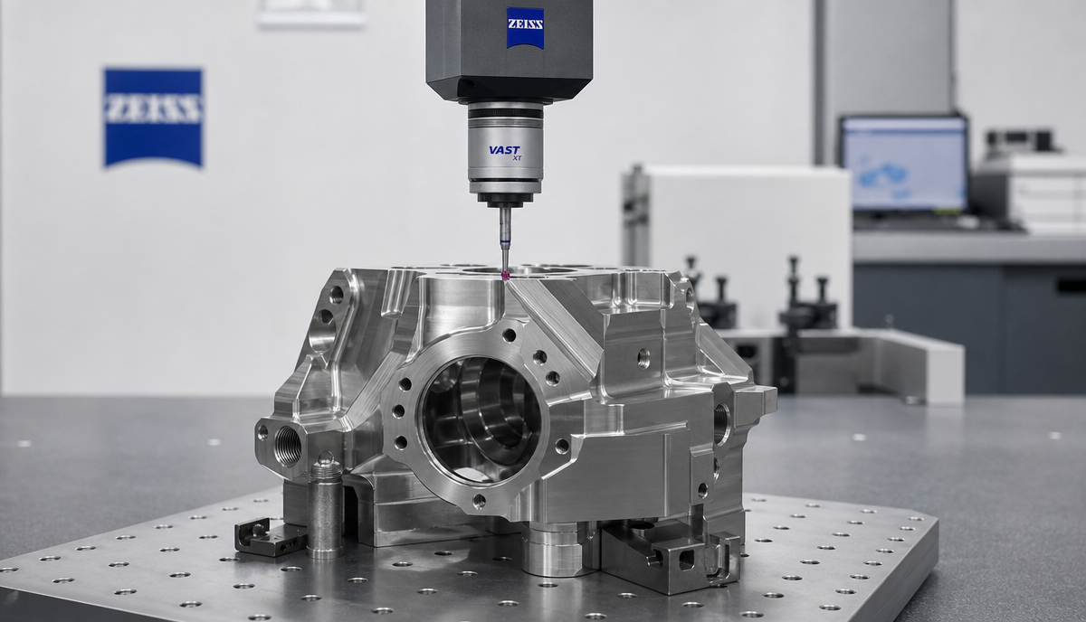
5-axis part inspection focuses on the features that matter — positional accuracy, surface quality, and critical dimensions across multiple faces.
First Article Inspection
CMM Measurement
Critical Hole Position
Flatness Check
Surface Profile
Thread Inspection
Surface Finish
Material Certification
5-Axis CNC Machining Case Study
Two representative projects showing how 5-axis capability addresses different material and geometry challenges.
Aluminum
Complex Structural Bracket
Stainless Steel
Corrosion-Resistant Valve Component
Where These 5-Axis Parts Are Used
Organized by part function — because the geometry requirement determines the manufacturing process, not the industry label.
Structural Components
Fluid-Handling
Precision Housings
Mounting Interfaces
Complex Brackets
Rotary Components
Instrument Parts
What Determines the Cost of a 5-Axis CNC Part?
5-axis is not automatically more expensive — or cheaper. The value comes when its capabilities offset the additional programming and setup investment.
Frequently Asked Questions
Have a Complex Part for 5-Axis CNC Machining?
Send your 3D CAD model, 2D drawing, material requirement and quantity. We will review tool access, workholding, machining strategy, critical tolerances and finishing requirements before quotation.
Request a 5-Axis Machining Quote