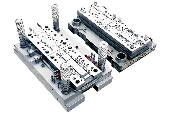
Precision CNC milling, turning and multi-axis machining for metal and plastic components with critical dimensional and geometric requirements. Tolerances down to ±0.005 mm may be supported on qualified features following drawing, material and inspection review.
Quick Capability Summary
This page is written for engineers and procurement specialists who already know what a tolerance is — and need to decide whether Goldcattle can hold their tolerance, verify it, and keep it through production. A 3D model defines geometry; a 2D drawing defines the critical dimensions, GD&T, datums, surface finish and inspection requirements. For tight-tolerance projects we strongly recommend both.
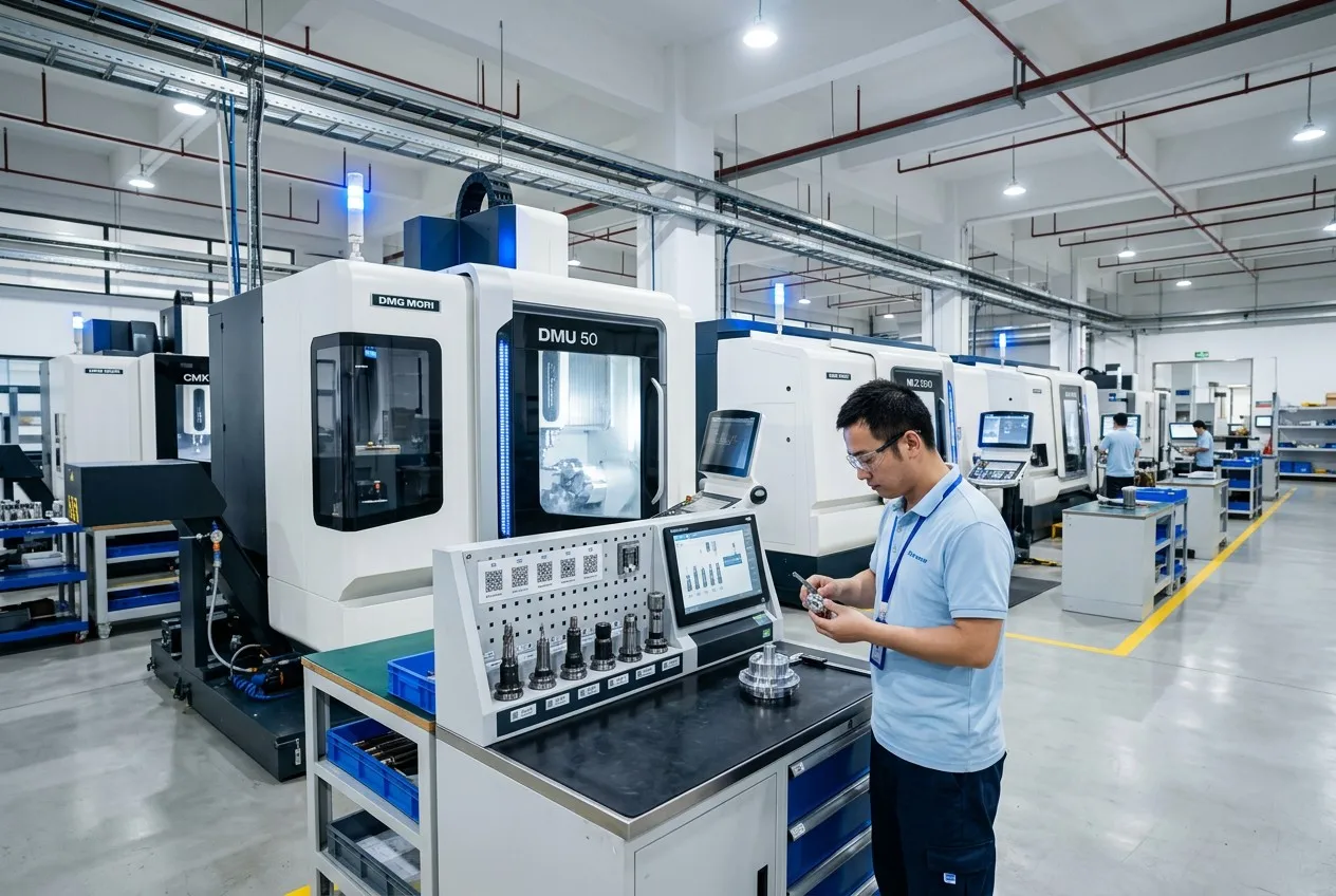
Manufacturing & Metrology Infrastructure
Precision is the output of equipment, measurement and process discipline — not a marketing number. Below is Goldcattle's typical configuration. Exact machine models, calibration certificates and live counts are provided during a supplier audit or on request.
Machining fleet (representative mix)
3-axis CNC machining centers
~40 units · prismatic parts, pockets, slots, flat profiles. Rigid structure for stable repeatability.
4-axis CNC machining centers
~25 units · indexable 4th axis for multi-face parts without re-clamping error.
5-axis CNC machining centers
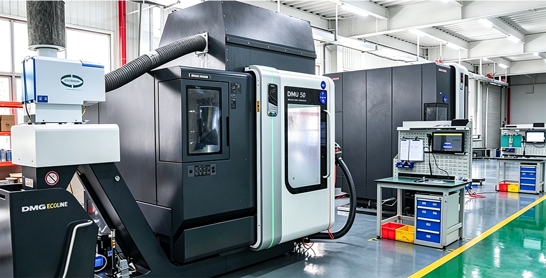
~12 units (DMG Mori / Mazak / Haas-class) · simultaneous 4+1 / 5-axis for complex geometry in one grip.
CNC turning & turn-mill
~20 units with live tooling · ODs, IDs, threads, cross-holes and milled features in fewer setups.
Swiss-type lathes
~8 units · slender, high-length-ratio rotating parts with tight runout.
Grinding / EDM (controlled)
Precision grinding, honing, wire & sinker EDM coordinated through audited sub-suppliers under Goldcattle QA; final inspection and responsibility stay with Goldcattle.
Metrology & inspection equipment
| Equipment | Class / capability | What it verifies |
|---|---|---|
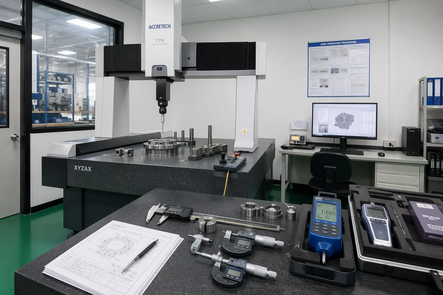
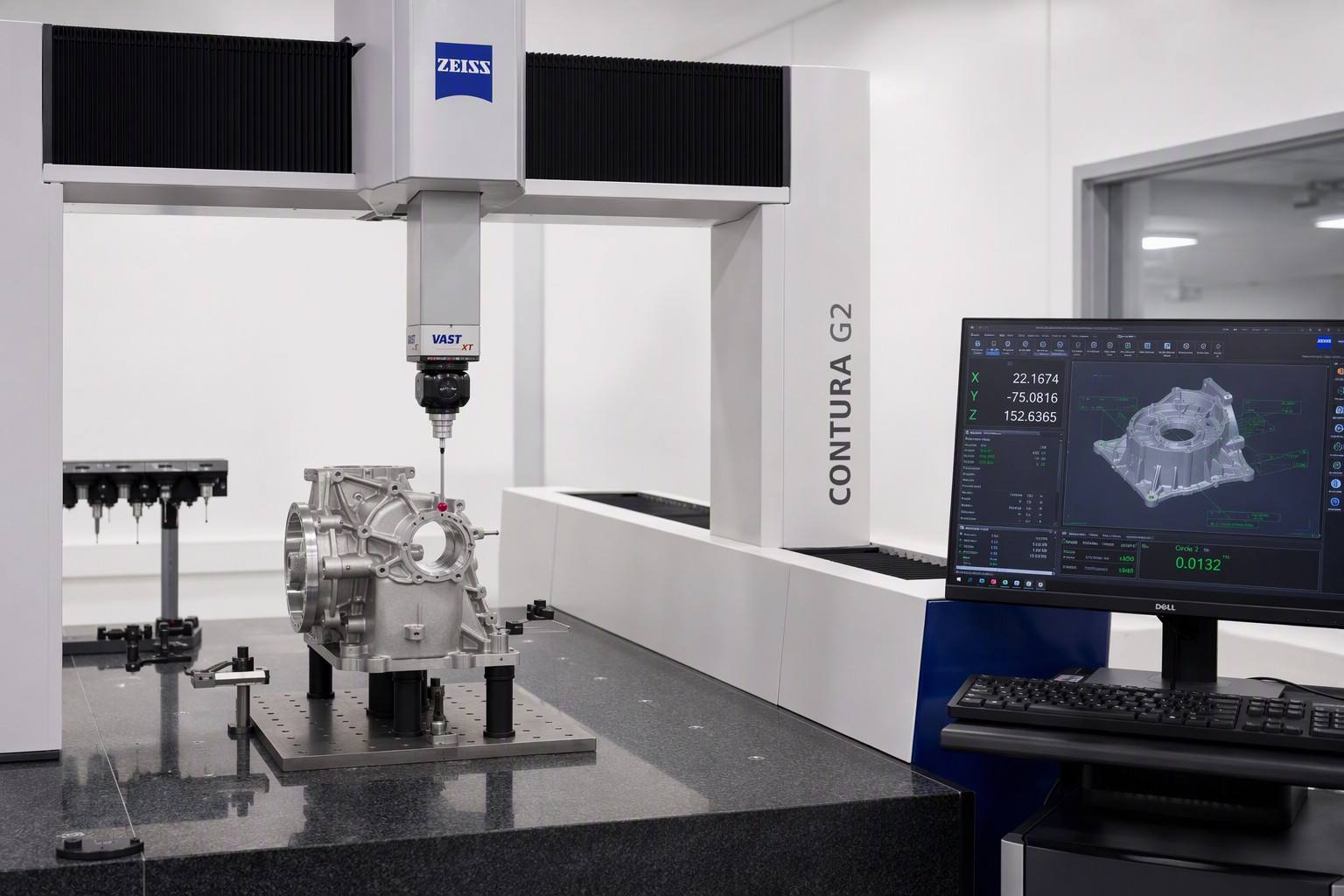
| Bridge-type CMM | Hexagon / Mitutoyo-class, scanning probe, ±0.005 mm accuracy class | Position, profile, flatness, runout, full GD&T |
| Digital height gauge | Trimos / Mitutoyo-class, 0.001 mm resolution | Step heights, parallelism, perpendicularity |
| Micrometer & bore-gauge sets | Outside / inside, pin & thread gauges | OD, ID, hole diameters, thread Go/No-go |
| Surface roughness tester | Portable profilometer, Ra / Rz | Finish requirement compliance |
| Optical profile projector / vision | 2D contour & edge measurement | Complex profiles, small features |
| Granite surface plates & hardness tester | Calibrated reference, Rockwell/Vickers | Flatness reference, material verification |
What Is Tight-Tolerance CNC Machining?
A tight tolerance is a dimensional or geometric requirement that needs more control than the standard machining tolerance normally applied to a part. What qualifies as "tight" depends on feature size, material, geometry, process, inspection method and functional requirement — not on a single number.
Standard vs tight-tolerance machining
| Requirement | Standard | Tight-tolerance |
|---|---|---|
| Drawing review | General review | Feature-by-feature tolerance review |
| Setup | Standard fixture | Datum-driven fixture & setup control |
| Tooling | General strategy | Tool wear & deflection management |
| Environment | Normal shop | Controlled measurement where required |
| Inspection | Sampling / basic | Defined method & reporting |
| Production | General repeatability | Process control for critical dimensions |
| Cost | Lower | Higher (control + inspection) |
| Documentation | Basic | FAI, CMM or critical-dimension reports |
Why "tight" is relative
- ±0.01 mm is routine for a small precision bore, but very difficult for a 600 mm thin plate.
- Linear size, position, circular runout and flatness are not interchangeable.
- Temperature, surface finishing and measurement method all shift the result.
- ISO 2768 is a general tolerances standard for undimensioned features — not a precision certificate, and not a replacement for explicit critical dimensions.
Tight-Tolerance Capabilities
Dimensional tolerances we control
Linear dimensions, hole and shaft diameters, slot widths, step heights, thread dimensions and wall thickness are reviewed feature by feature. The table below shows typical capability ranges; final numbers are confirmed against your drawing.
Geometric tolerances (GD&T)
| Geometric control | Typical application | Inspection method |
|---|---|---|
| Flatness | Sealing & mounting surfaces | CMM or surface measurement |
| Parallelism | Guide & mating faces | CMM / height measurement |
| Perpendicularity | Housing faces & bores | CMM |
| Position | Hole patterns & locating features | CMM |
| Concentricity / coaxial control | Shafts, bores, rotating parts | CMM / roundness equipment |
| Circular runout | Shafts & bearing seats | Dial indicator / CMM |
| Total runout | Multi-surface rotating parts | Specialized setup |
| Profile (line / surface) | Complex contours | CMM / scanning |
| Cylindricity | Precision bores & shafts | Roundness / cylindricity measurement |
Goldcattle tolerance capability matrix
Three tiers replace a single headline number. Standard = default quotable range. Enhanced = needs optimized process, dedicated tooling or added inspection. Review = confirmed only after seeing the drawing.
| Feature | Standard | Enhanced | Engineering review |
|---|---|---|---|
| Machined linear dimensions | ±0.02 mm | ±0.01 mm | ±0.005 mm on critical features |
| Precision holes | H9 | H7 | H6 / reamed, blind & deep holes |
| Shaft diameters | ±0.01 mm | ±0.005 mm | tighter with grinding |
| Hole position | ±0.05 mm | ±0.02 mm | ±0.01 mm, multi-datum / long patterns |
| Flatness | 0.05 / 100 mm | 0.02 / 100 mm | large planes / thin walls |
| Parallelism | ±0.03 mm | ±0.01 mm | long-span surfaces |
| Runout | 0.03 mm | 0.015 mm | 0.005–0.01 mm, complex datums |
| Surface roughness | Ra 1.6 µm | Ra 0.8 / 0.4 µm | Ra 0.2 µm with grinding / lapping |
How tolerance scales with feature size
A tolerance that is routine on a 5 mm bore is unrealistic on a 600 mm plate. The table below shows typical achievable linear tolerance against feature size — the basis for honest quoting, not a single headline number.
| Feature size (mm) | Standard capability | Enhanced (review) |
|---|---|---|
| 0.5 – 3 | ±0.01 mm | ±0.005 mm |
| 3 – 6 | ±0.02 mm | ±0.01 mm |
| 6 – 30 | ±0.03 mm | ±0.015 mm |
| 30 – 120 | ±0.05 mm | ±0.02 mm |
| 120 – 400 | ±0.10 mm | ±0.05 mm |
| 400 – 1000 | ±0.20 mm | ±0.10 mm |
Surface finish requirements
Specify surface finish only where it is functionally required. We achieve Ra 1.6 µm as standard and down to Ra 0.4 µm on reviewed features by finishing strategy; smoother values use grinding, honing or lapping. Over-specifying finish adds cycle time and cost without functional benefit.
CNC Processes for Precision Parts
Tight-Tolerance CNC Milling
For complex multi-sided parts: hole-pattern position, flatness and parallelism, deep-cavity and thin-wall control. 3+2 reduces re-clamping; continuous 5-axis holds free-form surfaces and reduces cumulative setup error. Datum faces and fixtures are planned up front.
Precision CNC Turning
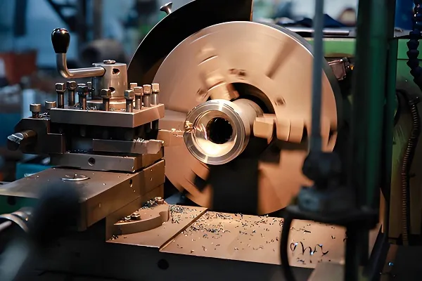
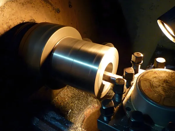
For critical ODs, IDs, shoulders, threads and runout on shafts, bushings and sleeves. Live tooling, secondary milling and turn-mill combine operations in fewer setups. Soft jaws, steady rests and dedicated fixtures control slender-part deflection.
Multi-Axis Machining
4- and 5-axis machining holds features on non-aligned faces in one grip — the single most effective control against accumulated positioning error on precision housings, manifolds and rotating components.
Secondary Precision Processes
CNC milling/turning and inspection are performed in-house. Precision grinding, honing, reaming and wire EDM are coordinated through audited sub-suppliers under Goldcattle's quality control; final inspection and responsibility remain with Goldcattle, and the process is documented in the inspection report. Quote includes these operations where required.
Materials for Tight-Tolerance Machining
How a material behaves under the cutter and after finishing changes what tolerance is realistic. The same ±0.005 mm strategy does not transfer directly between metals and plastics.
Aluminum
6061-T6 offers stable dimensions and good machinability; 7075 is stronger but residual stress must be considered. Thin walls need stress-relief control; anodizing adds coating thickness that changes fit dimensions — coated bores and seats are usually masked or machined after finishing.
Stainless Steel
303/304/316 cutting forces and heat are higher; work hardening and tool wear can drift size on long runs. Thin-wall parts are prone to deformation; flood coolant, rigid setups and in-process measurement keep dimensions stable.
Steel and Titanium
Carbon/alloy steel is stable in many geometries but heat treatment can distort; we machine before or after heat treat per the print. Titanium's low thermal conductivity demands heat management, spring-back awareness and tool-wear control.
Engineering Plastics
PEEK, POM, nylon and PC are temperature- and moisture-sensitive. Thermal expansion, moisture absorption and residual stress shift dimensions; measurement environment and part conditioning time matter. Plastic tight-tolerance strategy is not a copy of the metal strategy.
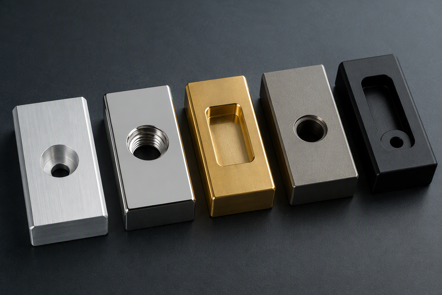
Material reference — typical grades & properties
| Material | Common grades | Tensile (MPa) | Machinability | Typical use |
|---|---|---|---|---|
| Aluminum | 6061-T6, 7075-T6, 2024-T4 | 310 – 572 | Excellent | Housings, brackets, fixtures |
| Stainless steel | 303, 304, 316L, 17-4PH | 485 – 1,310 | Fair (work-hardens) | Valves, medical, marine |
| Carbon / alloy steel | 1018, 4140, 4340 | 400 – 1,080 | Good | Shafts, structural |
| Brass | C360, H59 | ~385 | Excellent (100% ref) | Fittings, terminals |
| Titanium | Gr5 (Ti-6Al-4V) | ~950 | Difficult (low conductivity) | Aerospace, medical |
| PEEK | Industrial / medical | ~100 (flex) | Good, heat-sensitive | Insulators, wear parts |
| POM / Acetal | POM-C, POM-H | ~70 | Good | Precision gears, guides |
| Nylon / PA | PA66 | ~80 | Good, moisture-sensitive | Bushings, rollers |
| Material group | Machining considerations | Tight-tolerance risks |
|---|---|---|
| Aluminum | Good machinability, thermal conductivity | Thin-wall distortion, anodizing buildup |
| Stainless steel | Work hardening, higher forces | Tool wear, heat, deformation |
| Carbon / alloy steel | Stable in many geometries | Heat-treatment distortion |
| Brass | Good machinability | Burr control, cosmetic damage |
| Titanium | Low thermal conductivity | Heat, spring-back, tool wear |
| PEEK | Temperature-sensitive plastic | Thermal expansion, residual stress |
| POM / Acetal | Good machinability | Dimensional change with temperature |
| Nylon | Moisture absorption | Dimensional instability after machining |
Factors That Affect Achievable Tolerance
Part & process side
- Feature size and aspect ratio
- Wall thickness and rigidity
- Datum scheme and tolerance chain
- Number of setups and clamping points
- Tool deflection and wear
- Heat generated during cutting
Material & environment side
- Material state (annealed, heat-treated, stressed)
- Residual stress release
- Surface finishing added afterward
- Measurement temperature
- Part conditioning (plastics)
- Inspection method and equipment
How Goldcattle Controls Critical Dimensions
1 · Drawing & tolerance review
Critical dimensions, datum system, tolerance chain, GD&T, material state, heat treat, finishing and measurement method are reviewed before quoting.
2 · Datum-driven planning
Manufacturing datums map to design datums; features held in one setup; clamping-error chains kept as short as the geometry allows.
3 · Fixture design
Dedicated fixtures, soft jaws, thin-wall support and controlled clamping force for repeatable location.
4 · Tool & cutting strategy
Roughing/finishing separation, finishing allowance, tool-wear monitoring, deflection compensation and stable parameters.
5 · In-process control
First-piece check, in-process sampling, tool-life management, offset compensation, machine warm-up and non-conformance isolation.
6 · Measurement & final inspection
Critical dimensions are allowed to stabilize before final inspection where temperature sensitivity may affect results; calibrated equipment, defined method, inspection report.
Where Precision Is Won or Lost — 5 Controls
Tight tolerance is the result of proactive risk control, not just a precise machine. These are the failure modes we manage during DFM and production.
1 · Datum & fixturing repeatability
Risk: cumulative error from multiple setups and datum stack-up.
Control: single-setup 4-/5-axis and zero-point fixturing to eliminate re-clamp shift; manufacturing datums mapped to design datums.
2 · Tool deflection & reach
Risk: vibration, chatter and size drift in deep cavities (high length-to-diameter ratio).
Control: staged roughing → semi-finish → finish with short, rigid tools; in-process measurement on long features.
3 · Thermal drift
Risk: dimensional fluctuation from spindle heat and ambient temperature change.
Control: machine warm-up routine, parts allowed to stabilize before critical measurement, inspection at controlled temperature where sensitivity matters.
4 · Thin-wall vibration & distortion
Risk: elastic deformation and stress release on walls <0.8 mm.
Control: symmetric material removal, support fixtures, optimized toolpaths and, for aluminum, stress-relief before final cut.
5 · CAM path & collision
Risk: uneven scallop height and tool-holder interference on complex geometry.
Control: constant-step finishing passes, 5-axis collision verification, and feed/speed tuned to material and feature.
Inspection Equipment & Quality Documentation
Every method below is tied to what it measures — equipment is shown with its purpose, not just a brand. Inspection method is agreed before production.
| Requirement | Possible inspection method |
|---|---|
| External diameter | Micrometer or CMM |
| Precision bore | Bore gauge, pin gauge or CMM |
| Hole position | CMM |
| Flatness | CMM or surface-based measurement |
| Runout | Indicator setup or CMM |
| Surface roughness | Profilometer |
| Thread | Go/no-go gauge or thread measurement |
| Complex profile | CMM or optical scanning |
Documentation we can supply
First Article Inspection (FAI) report · CMM dimensional report · critical-dimension inspection report · Certificate of Conformance (CoC) · material certificate · surface-treatment / heat-treatment certificate · RoHS / REACH documents · lot inspection record. PPAP and control-plan documents are available where the program requires them — confirm at quotation.
Tolerance Control Before and After Surface Finishing
Anodizing, plating, powder coating, black oxide, passivation, polishing and heat treatment all change a dimension. We plan for it rather than discovering it after the fact.
What we control
- Coating build-up or material removal is calculated into the machined size.
- Bearing seats, precision bores, threads, sealing and contact surfaces are masked where the print requires.
- Critical dimensions are inspected both before and after finishing when the tolerance applies to final condition.
What the drawing must state
Critical dimensions should indicate whether the tolerance applies before or after plating, anodizing, heat treatment or other secondary processing. Ambiguous "±0.01 mm" on a plated bore without a condition is the most common cause of fit failure — we will flag it during review.
From First Article Approval to Repeat Production
"The sample was perfect, the batch drifted" is the fear we design against. Controls carried from first article to volume:
Process locked at FAI
CAM program version, fixture number, tool list and parameters recorded against the approved sample.
Golden sample & lot trace
Reference sample retained; material heat/lot recorded per order for追溯.
Change control
Drawing revision (ECN) and any process change re-trigger review — no silent changes to a running part.
Production sampling
Defined in-process and final sampling frequency for critical dimensions, agreed per program.
DFM Guidelines for Tight-Tolerance Parts
| Design area | Recommended approach | Risk when over-constrained |
|---|---|---|
| Critical dimensions | Tighten only function-critical features | Higher cost & inspection time |
| Datum system | Use functional, measurable datums | Ambiguous inspection results |
| Deep holes | Realistic depth-to-diameter ratio | Tool deflection, poor evacuation |
| Thin walls | Increase thickness where possible | Distortion & chatter |
| Internal corners | Use practical radii | Small tools, longer machining |
| Hole position | Define functional datum references | Datum disagreement |
| Surface finish | Specify only where necessary | Longer finishing cycle |
| Plated dimensions | Define final condition | Fit failure after finishing |
| Plastics | Account for temperature & moisture | Dimensional drift |
| Tolerance stack | Control functional interfaces | Unnecessary individual tight tolerances |
Typical Parts & Applications
Shown by the requirement they share, not just by industry — this is what helps an engineer self-qualify.
Precision bores & fits
Bearing seats, bushings, valve bores, locating holes.
Multi-feature positional control
Manifolds, hydraulic blocks, equipment housings, fixture plates.
Rotating components
Shafts, spindles, sleeves, coupling components.
Flatness-critical parts
Mounting plates, sealing faces, heat-sink bases, optical platforms.
Industries served
Fluid control, robotics, medical equipment, semiconductor tooling, automotive & EV fixtures, industrial automation, aerospace-style structures.
Material & process fit
Aluminum & stainless for most; titanium & PEEK where weight, corrosion or temperature demand it.
Tight-Tolerance Machining Case Studies
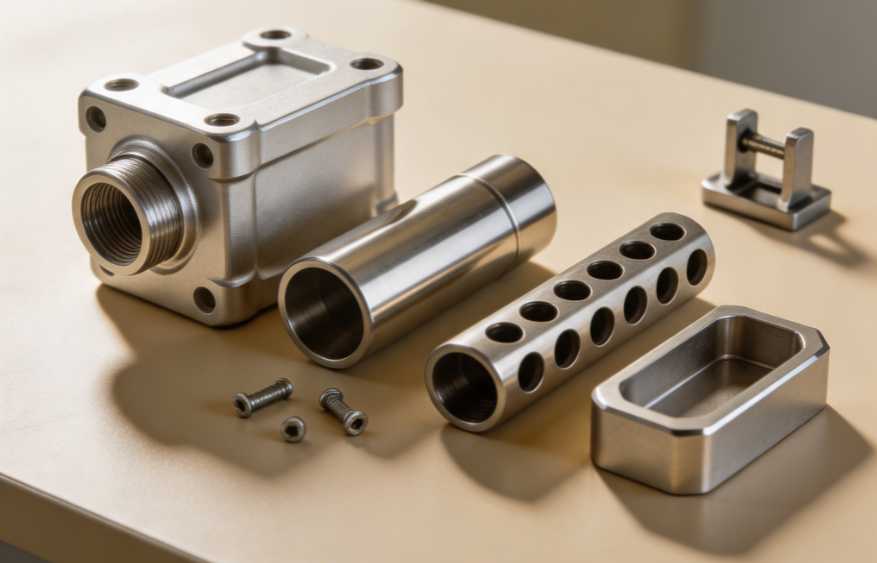
The following are representative project profiles based on part types Xiamen Goldcattle routinely manufactures. Exact measured results are confirmed per project under NDA — we do not publish unverified micron claims or named customer drawings.
Case: Precision Aluminum Manifold
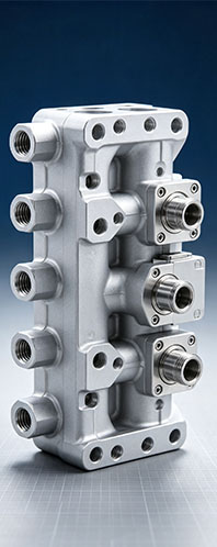
| Material | Aluminum 6061-T6 |
| Process | 4-axis CNC milling + reaming |
| Quantity | Prototype + repeat production |
| Critical requirement | Intersecting port position and bore fit |
| Surface finish | Anodizing (masked seats) |
| Inspection | CMM + precision bore measurement |
| Challenge | Multiple intersecting ports with positional relationships; coating build-up on fitted bores |
| Solution | Datum-controlled setup, dedicated finishing tools, machined-after-anodize on critical bores, post-process CMM |
| Result | Port position ⌀0.03 mm called, held ⌀0.015 mm; bore to H7 after anodize; CMM dimensional report per batch |
| Measured outcome | Representative: position deviation < 50% of tolerance; fit verified on every batch |
Case: Stainless Precision Fitting
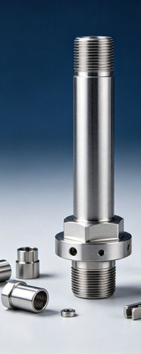
| Material | Stainless steel 316L |
| Process | CNC turning + live tooling |
| Quantity | Low-volume production |
| Critical requirement | OD/ID runout on a slender rotating feature |
| Surface finish | Electropolish / passivation |
| Inspection | Indicator runout + CMM |
| Challenge | Work hardening and deflection on a long, thin section |
| Solution | Steady-rest support, rigid tooling, in-process measurement, post-finish runout check |
| Result | Runout 0.02 mm called, held 0.008 mm; Ra 0.4 µm after electropolish; material cert & CoC per lot |
| Measured outcome | Representative: runout ~40% of called limit; surface finish to medical spec |
Case: Multi-Datum Housing
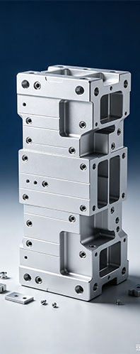
| Material | Aluminum 7075 |
| Process | 5-axis machining, single setup |
| Quantity | Prototype → production |
| Critical requirement | Position of patterned holes + flatness of mounting face |
| Surface finish | Ra 0.8 µm on mating face |
| Inspection | CMM full report |
| Challenge | Holding position across non-aligned faces without re-clamping error |
| Solution | One-grip 5-axis, datum face preserved, CMM per batch |
| Result | Pattern position ⌀0.05 mm called, held ⌀0.02 mm; mounting flatness 0.02/100 mm; Ra 0.8 µm on mate |
| Measured outcome | Representative: position deviation < 40% of tolerance; repeatable across batches |
How Goldcattle Meets Your Supplier-Evaluation Criteria
Selecting a precision supplier is risk management, not price comparison. Below we answer the criteria procurement and quality teams actually score — including the red flags we deliberately avoid.
| What you evaluate | How Goldcattle responds |
|---|---|
| Machine capability | 3-/4-/5-axis machining centers, turn-mill and Swiss-type lathes; single-setup multi-axis to avoid tolerance stacking. |
| Quality management system | ISO 9001-documented QC with CMM verification; industry certs (IATF 16949 / AS9100 / ISO 13485) available per program. |
| Material expertise | Proven cutting strategies for aluminum, stainless, titanium and engineering plastics — deformation, work-hardening and burr control by material. |
| DFM / engineering support | Pre-quote drawing review; we propose relaxing non-functional tolerances and flag fit-risk before production. |
| Delivery performance | Prototype and production scheduling with defined sampling; progress visible through the program. |
| In-house vs outsourcing | Machining and inspection in-house; grinding / EDM / plating through audited sub-suppliers under Goldcattle responsibility — no silent subcontracting. |
| Traceability | Material certificate, lot/heat record and retained golden sample per order. |
| Inspection documentation | FAI, CMM dimensional report, CoC and MTR supplied on request; PPAP / control plan where the program requires. |
Red flags we avoid
We review 2D + 3D
We do not quote from a 3D model alone. Critical dimensions, GD&T, datums, finish and inspection method are confirmed up front — exactly where vague suppliers lose projects.
We ask the right questions
Material grade, surface treatment, critical features and inspection method are discussed before quoting, not discovered after production.
We provide evidence
Sample CMM reports and material certificates are available on request — we do not answer tolerance questions with unverifiable claims.
We separate prototype from production
First-article process is locked and carried to volume; we design against "perfect sample, drifting batch."
Full framework: Precision CNC Machining Supplier Selection Guide.
Frequently Asked Questions
What tolerance can Goldcattle achieve?
Is ±0.005 mm available on every dimension?
Do you require a 2D drawing?
Can you inspect GD&T requirements?
Can you provide a CMM report?
How does tight tolerance affect CNC machining cost?
Can you hold tight tolerances after anodizing or plating?
Can engineering plastics hold the same tolerance as metals?
Do you support prototype and production quantities?
What files are needed for a quotation?
Can you review an existing supplier quality problem?
Can you manufacture mating parts as an assembly?
Request a Tight-Tolerance Machining Review
Upload your 2D drawing and 3D model. Please identify critical dimensions, datum references, surface-finishing requirements, inspection documentation and expected production volume — our engineers will review manufacturability and quote by feature.
Files accepted: PDF, STEP/STP, X_T, IGES, DWG, DXF, ZIP. Drawings and project files are used only for engineering review and quotation. NDA support is available upon request.