"What Tolerance Can You Hold on a Contoured Surface — Not on a Flat Test Coupon?"
The Tiered Tolerance System We Use and What Each Tier Actually Requires
Machine specification and part tolerance are different things. A machine's positioning accuracy describes the platform; the tolerance held on your part additionally depends on geometry, material, fixture rigidity, tool length, thermal state, cutting strategy and measurement method. This page publishes what we hold in practice on multi-axis work — separated into tiers so you can see which category your requirements fall into before we quote.
The Short Answer
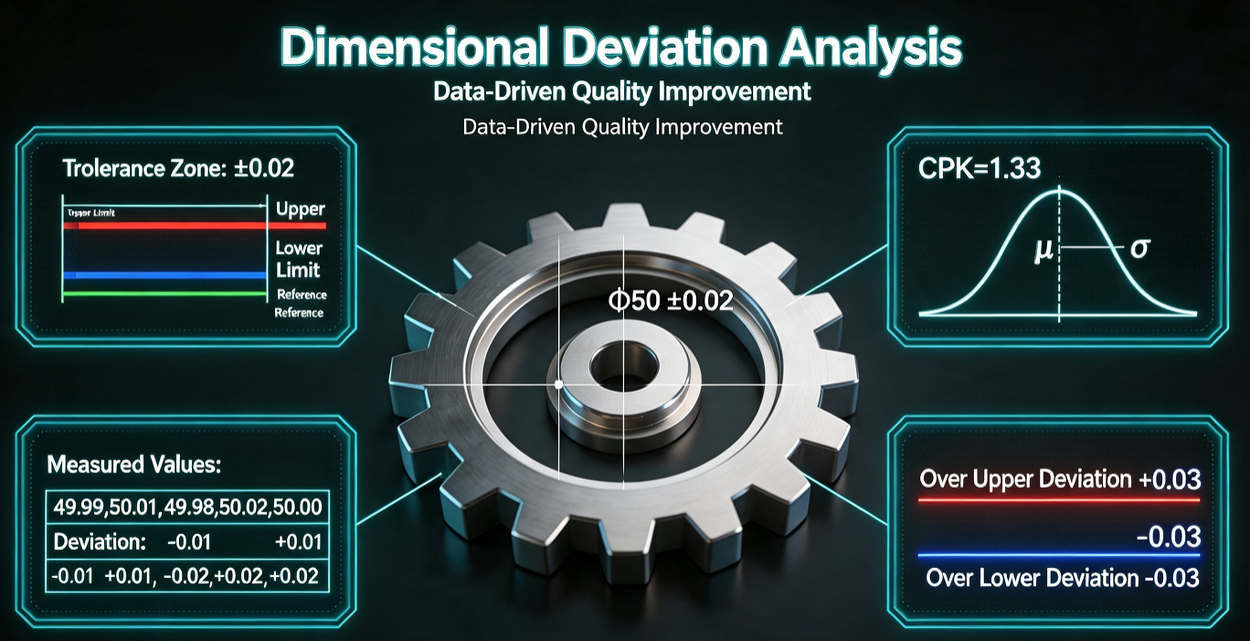
We publish a three-tier tolerance system because not all dimensions on a complex part require the same level of control. Applying review-tier process to every feature would make your parts unnecessarily expensive; applying standard-tier process to critical features would risk non-conformance.
- Standard capability: what we hold routinely on multi-axis work without special measures. Suitable for general-precision components where tolerances match typical drawing defaults.
- Enhanced capability: achievable with controlled conditions (thermal management, dedicated fixturing, reduced tooling overhang). Suitable for precision instruments, fluid-power components and assembly-critical features.
- Engineering-review required: possible on reviewed features under specific conditions. Requires feature-by-feature assessment, process validation and often higher inspection cost. Suitable for aerospace-style, medical-equipment or metrology-grade applications.
Tiered Tolerance Table: What We Hold in Practice
These figures are based on actual measurement data from our multi-axis production work. They represent typical achieved values, not machine catalogue specifications. The "Review Required" column indicates thresholds that need engineering assessment before we commit.
| Characteristic | Standard Capability | Enhanced Capability | Engineering Review Required |
|---|---|---|---|
| Linear dimension (<100 mm) | ±0.05 mm | ±0.02 mm | Tighter than ±0.01 mm |
| Linear dimension (100–300 mm) | ±0.08 mm | ±0.03 mm | Tighter than ±0.02 mm |
| Bore diameter (reamed / bored) | ±0.02 mm (IT8) | ±0.01 mm (IT6) | H6 or tighter (IT5 or below) |
| True position (hole pattern) | ∅0.05 mm at MMC | ∅0.02 mm at MMC | Tighter than ∅0.015 mm at MMC |
| Surface profile (contoured) | 0.05 mm vs CAD nominal | 0.02 mm vs CAD nominal | Tighter than 0.015 mm |
| Runout / concentricity | 0.02 mm | 0.01 mm | Tighter than 0.008 mm |
| Flatness (sealing face) | 0.03 mm / 300 mm | 0.015 mm / 300 mm | Tighter than 0.01 mm / 300 mm |
| Surface roughness Ra (milled, aluminium) | Ra 1.6 µm | Ra 0.8 µm | Ra 0.4 µm or finer |
| Surface roughness Ra (milled, steel / SS) | Ra 1.6 µm | Ra 1.0 µm | Ra 0.6 µm or finer |
| Wall thickness (thin-wall aluminium) | ±0.10 mm (nominal ≥1.5 mm wall) | ±0.05 mm (nominal ≥1.2 mm wall) | Below 0.8 mm nominal wall |
| Angle (compound bore / face) | ±0.05° | ±0.02° | Tighter than ±0.01° |
What Determines Which Tier Your Part Falls Into
Achievable tolerance is not determined by the machine alone. It is the product of six factor groups. Understanding which factors are limiting your current supplier's output helps diagnose whether the problem is equipment, process, or both.
1. Machine Platform Contribution
- Rigid cast-iron or polymer-concrete machine base
- Direct measuring systems (linear scales) on linear axes, not rotary encoders on ball screws
- Cooled rotary bearings and integrated thermal management
- Rotary-axis encoder feedback (not just motor-step counting)
- Thermal compensation functions active in the CNC control
- Spindle thermal stability (warm-up protocol before precision cuts)
2. Process Contribution (What We Control)
- Temperature-stabilised inspection environment (±1°C) for critical measurement
- Tool-life monitoring: scheduled replacement on tolerance-critical features before wear exceeds limit
- Spindle warm-up cycles before precision finishing runs
- Controlled finishing stock: separate finishing pass with predictable material removal
- First-article verification before batch release
- In-process probing to detect drift during long production runs
3. Part-Level Factors (What You Control)
- Material: aluminium machines more easily than titanium or hardened steel at equivalent tolerance
- Size: larger parts accumulate more thermal error; thin walls amplify clamping distortion
- Geometry: deep cavities force long tools (more deflection); contoured surfaces need shorter tools via tilt access
- Tolerance distribution: concentrating tight tolerances on fewer features reduces cost versus tight-tolerance-all-over
- Drawing clarity: unambiguous GD&T datums prevent measurement-system disagreement between supplier and customer
Contoured Surface Tolerances: Why Flat Coupons Don't Tell the Full Story
A common sourcing frustration: a supplier's capability brochure shows impressive tolerance numbers measured on a flat test coupon (or a simple calibration artefact), but your contoured part arrives out of tolerance. The difference is not dishonesty — it is geometry.
Why Contoured Surfaces Are Harder to Hold
- Tool deflection varies along the path: as tool engagement angle and depth of cut change on a curved surface, cutting force direction and magnitude shift → the cutter bends differently at different points on the surface
- Longer effective reach: accessing deep passages or undercuts requires extended tool overhang even when the nominal tool length is short; deflection increases with the cube of overhang
- Measurement complexity: verifying a flat surface to ±0.005 mm requires one CMM probe approach; verifying an impeller blade profile to 0.03 mm requires hundreds of points, correct datum alignment, and specialised path planning
- Thermal asymmetry: uneven material removal across a contoured part creates non-uniform thermal gradients that shift the part differently in different regions
- Finish-pass consistency: maintaining uniform stock allowance on a compound-curvature surface across a batch requires stable tool wear compensation and consistent datum establishment
How We Close the Gap Between Coupon and Contoured Reality
- Shorter effective tool length: use 5-axis tilt to approach surfaces with the shortest possible tool stick-out, reducing deflection at source
- Zoned finishing: divide contoured surfaces into regions with matched tooling and parameters rather than one-size-fits-all finish pass
- Controlled stock allowance: semi-finishing leaves 0.15–0.25 mm predictable stock; finish pass removes exactly that amount with known tool pressure
- Thermal pause before finish: allow part temperature to stabilise after roughing before starting the finish pass that determines final accuracy
- CMM scanning vs point measurement: for contoured surfaces, scanning or dense-point measurement reveals deviation patterns that spot-checking misses
Thermal Control: The Invisible Tolerance Consumer
Temperature change is one of the largest sources of dimensional variation in precision machining, yet it is frequently unmanaged in shops that focus only on machine specification. Here is how heat affects your part and what we do about it.
| Heat Source | Effect on Part Dimension | Magnitude (Typical Range) | Our Control Measure |
|---|---|---|---|
| Spindle warm-up | Z-axis drift as spindle bearings expand; rotary-axis thermal growth | 0.005–0.020 mm Z-drift in first 30–60 min | Mandatory spindle warm-up cycle before any precision operation; temperature monitoring |
| Cutting energy (roughing) | Part heats unevenly where material removal is concentrated; local expansion shifts machined surfaces | 5–20°C rise possible in high-MRR aluminium roughing | Controlled roughing passes with coolant; thermal pause before semi-finishing |
| Coolant temperature variation | Part dimension changes if coolant temperature fluctuates between start and end of run | <0.001–0.003 mm per °C for aluminium (CTE ~23 µm/m/°C) | Coolant temperature management; avoid topping up with cold coolant mid-run |
| Ambient shop temperature swing | Machine structure and part both expand/contract with room temperature | 0.010–0.030 mm over a day with 5°C ambient swing on large parts | Stable shop environment; critical measurements in temperature-controlled inspection area |
| Long production runs | Cumulative thermal drift: early parts differ from late parts even if all other factors are constant | Observed drift of 0.005–0.015 mm over 4–8 hour runs on unmonitored machines | In-process probing at defined intervals; trend monitoring; feed adjustment if drift detected |
Frequently Asked Questions
Can you hold ±0.005 mm on my part?
Why is surface profile tolerance harder to achieve than linear dimension tolerance?
Do you guarantee these tolerances contractually?
How does material affect achievable tolerance?
Need to Verify Whether Your Tolerances Are Achievable?
Send your drawing with tolerances called out. We will map each requirement against our tiered system, flag any features that need engineering review, and give you a transparent quote that reflects the actual control level required — no hidden surcharges after the fact.
Feature-by-feature analysis included in every RFQ response. No obligation.