Case Study — Aerospace / Turbomachinery
Inconel 718 Impeller 5-Axis CNC Machining Case Study
A 248 mm turbomachinery impeller with 17 curved blades, machined from solid Inconel 718 in a single primary setup. This page documents the customer requirement, the engineering constraints, how the part was actually made, and what was measured before it shipped.
- Part
- Turbomachinery impeller
- Material
- Inconel 718
- Process
- Simultaneous 5-axis CNC
- Machine
- DMG MORI DMU 50
- Lead Time
- 8 business days
Project Overview
This impeller brought together three constraints that are individually manageable but difficult in combination: a nickel-based superalloy with poor machinability, blade geometry that severely restricts tool access, and blade-to-hub relationships that could not tolerate datum transfer between setups.
The part is a 248 mm diameter impeller with 17 curved blades, machined from solid rather than from a casting. Machining from solid removes the variables that come with cast blanks — porosity, inconsistent allowance, and the datum ambiguity of a near-net shape — but it puts the entire material removal burden onto the cutting strategy.
Rather than present this as a showcase, this page is written as an engineering record: what the customer asked for, what made the part difficult, which decisions were taken and why, and what evidence was produced. If you are evaluating whether the same discipline can be applied to your own geometry, the Inspection & Verification and Final Result sections are the ones that matter.
Xiamen Goldcattle Plastic & Metal Products Co., Ltd. has been manufacturing custom precision components since 1998, operating under an ISO 9001:2015 certified quality management system.
Customer Requirement
What the customer specified on the drawing and in the RFQ — the reference everything downstream was measured against.
- Part description
- Turbomachinery impeller with curved blade passages
- Material
- Inconel 718 (AMS 5662 / UNS N07718)
- Quantity
- Per customer RFQ
- Critical features
- 17 curved blade passages; hub-to-blade profile continuity; bore and mounting datum
- Dimensional tolerance
- Critical dimensions per drawing*
- Surface finish
- Ra 0.8 µm on blade airfoil surfaces
- Inspection
- CMM profile scan of blade surfaces; dimensional inspection of critical features
- Documentation
- First Article Inspection per AS9102; material certificate per EN 10204 3.1
* Fabrication and inspection were carried out against the customer drawing. Specific callouts are confirmed at quotation and recorded in the inspection report — we do not substitute a generic "shop standard" tolerance for a drawing requirement.
Engineering Challenges
Four constraints shaped every downstream decision. Each one on its own is routine; together they determined the machine, the setup count and the toolpath strategy.
-
1
Restricted blade access
The gap between adjacent blades limits both cutter diameter and shank clearance. As the cutter works toward the hub, the available approach angle narrows and the risk of shank or holder collision against the neighbouring blade rises sharply. Tool length had to be kept as short as the geometry allowed while still reaching the root of each passage, and every toolpath was checked against the full holder assembly — not just the cutting flutes.
-
2
Complex curved surfaces
Each blade is a compound-curved airfoil, not a ruled surface. Holding a consistent Ra 0.8 µm finish across the blade requires continuous control of the tool orientation relative to the surface normal. An indexed 3+2 approach would have left facet marks and inconsistent cusp heights between passes, so continuous simultaneous motion was required rather than a series of fixed-angle cuts.
-
3
Datum stability
The dimensional relationship between the hub, the bore and the blade tips cannot be re-established accurately once the part is unclamped. Any secondary setup introduces a datum transfer error that would show up as blade-to-blade profile variation. The blade-to-hub relationship therefore had to be maintained within a single clamping, from roughing through to finishing.
-
4
Inconel 718 machinability
Inconel 718 work-hardens rapidly and retains strength at elevated cutting temperatures. Cutting forces and heat concentrate at the tool edge, which makes chip evacuation and thermal load the controlling variables. Poor parameter selection in this material produces surface integrity problems — tensile residual stress, a work-hardened layer, or micro-cracking — that are not visible to the eye but matter on a rotating part.
Manufacturing Strategy
Five decisions, each traceable to one of the challenges above. The machine was selected to serve the geometry — not the other way round.
-
1
Machine: DMG MORI DMU 50
A 5-axis simultaneous machining centre with B-axis tilt and a 360° rotary C-axis. It was selected for the combination of rotary range and structural rigidity needed to hold tool orientation on the blade surfaces while cutting a nickel superalloy. Rigidity matters here because Inconel 718 punishes any compliance in the setup with chatter and rapid tool wear.
-
2
Simultaneous 5-axis, not indexed 3+2
Blade finishing used continuous simultaneous 5-axis motion rather than indexed 3+2 positioning. Indexed machining locks the tool at a fixed angle for each cut, which leaves visible facet boundaries on a compound curve. Continuous motion keeps the cutter in contact with the surface at a controlled, continuously varying angle, which is what produced the consistent finish across the airfoil.
-
3
Single primary setup
The part was planned around one primary setup so that hub, bore and blade geometry all remained referenced to a single machine datum. This removed the datum transfer step between roughing and finishing entirely. Where a subsequent operation was unavoidable, it was planned to reference the same datum features rather than establishing a new one.
-
4
Toolpath strategy
Toolpaths were generated from the customer 3D model with explicit tool-axis control and collision checking against the adjacent blades and the hub. Cutting parameters were selected to maintain constant tool engagement on the airfoil rather than constant step-over — a meaningful difference in Inconel 718, where sudden changes in engagement angle drive both tool wear and surface integrity.
-
5
Machining sequence
Roughing removed the bulk of the material while leaving a controlled allowance, followed by semi-finishing and then finishing passes on the blade surfaces. Hub and mounting features were completed within the same clamping. Separating roughing from finishing allows stress redistribution to occur before the final passes, so the finished geometry is not distorted by material removed after it.
Material — Inconel 718
Inconel 718 is a precipitation-hardening nickel-chromium superalloy. It is specified where a part must retain strength at elevated temperature and resist oxidation and creep — turbine engines, nuclear internals, deep-sea oil and gas equipment, and cryogenic service.
Those same properties are what make it difficult to machine. The alloy work-hardens quickly, has low thermal conductivity (so heat stays at the cutting edge rather than leaving with the chip), and maintains high strength at the temperature generated during cutting. The practical consequences are higher cutting forces, concentrated heat at the tool edge, and a hard surface layer if a pass is taken too lightly or a tool is allowed to dwell and rub.
Every batch is supplied with EN 10204 3.1 material certification, so the composition and mechanical properties of the stock are documented before any cutting begins.
- Designation
- UNS N07718 / AMS 5662
- Alloy type
- Nickel-chromium, precipitation hardening
- Key property
- Retains strength at elevated temperature
- Machining note
- Work-hardens rapidly; low thermal conductivity
- Hardness
- Per material certificate*
- Certification
- EN 10204 3.1 supplied with every batch
- Related alloys
- Inconel 625 / 600 / 601, X-750, Hastelloy C-276
* Hardness and mechanical properties are taken from the mill certificate for the specific batch supplied, not quoted from a generic datasheet.
Technical Specifications
The four figures that define this part.
- 248 mmOutside diameter
- 17Curved blades
- ±0.005 mmCritical dimensions*
- Ra 0.8 µmBlade airfoil finish
* Achieved on critical dimensions as defined on the customer drawing. This is a dimensional tolerance, not a profile-of-a-surface callout — the two are not interchangeable and we report them separately. Figures describe this specific part and are not a blanket guarantee for other geometries.
Inspection & Verification
Three distinct activities. They are often conflated in supplier marketing — they are not the same thing.
-
CMM profile scan
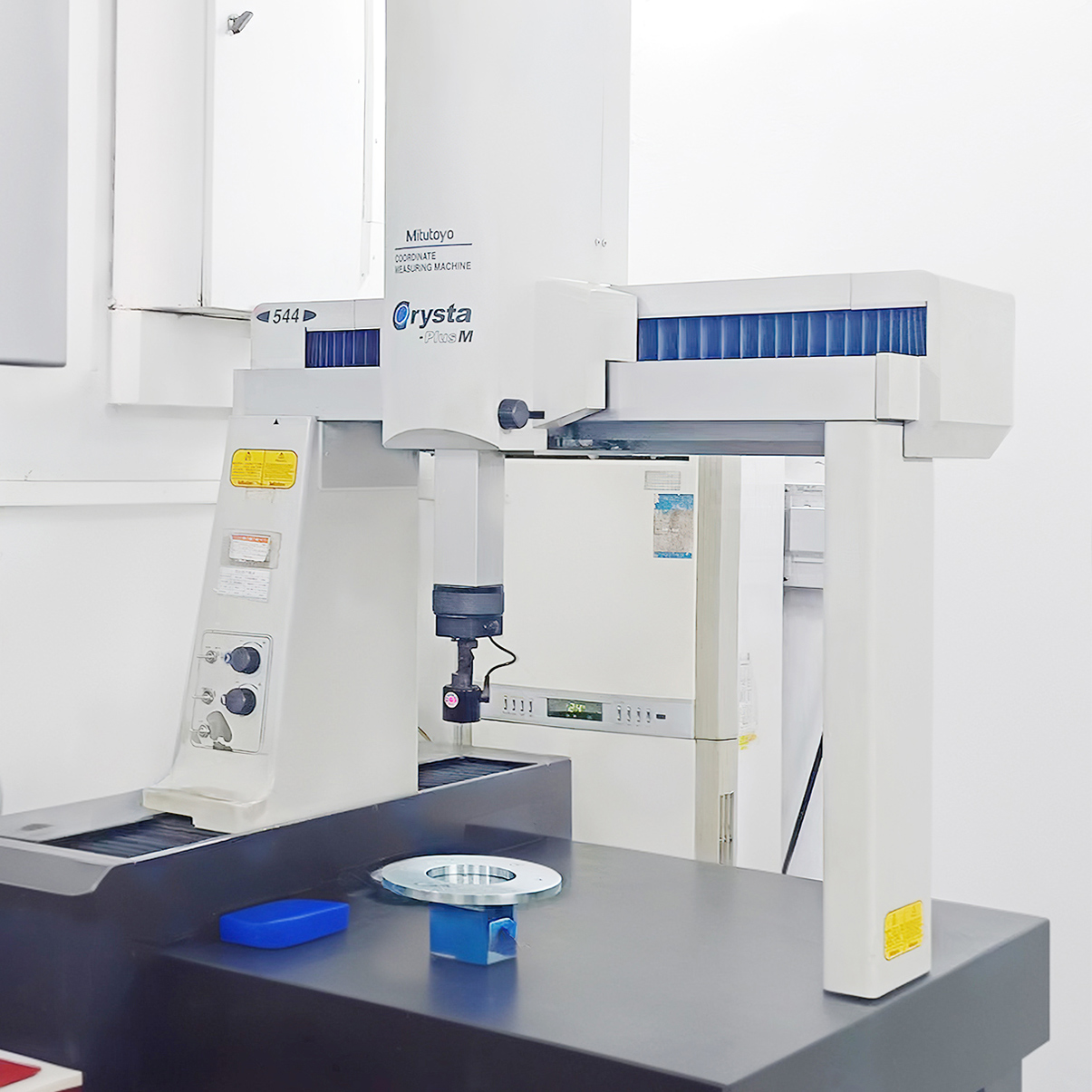
The blade airfoil surfaces were scanned on a coordinate measuring machine and compared against the nominal geometry. The point of a scan, as opposed to discrete point measurement, is that deviation is evaluated across the whole surface — so a localised high spot between measured points is still detected. This is the only practical way to verify a compound-curved airfoil.
-
Dimensional inspection
Critical features — bore, mounting datum and hub dimensions — were measured against the drawing and recorded in the inspection report. This covers the features that govern how the impeller locates and seals in its assembly, which is where fit problems originate if they are wrong.
-
First Article Inspection per AS9102
A first article inspection documenting measured results for the characterised features. One clarification we make deliberately: AS9102 is a first article inspection standard, not a certification. We report "FAI per AS9102" because that is accurate. A supplier claiming to be "AS9102 certified" is describing something that does not exist.
Final Result
- Tolerance
- Critical dimensions to drawing*
- Surface finish
- Ra 0.8 µm on airfoils
- Inspection
- CMM profile + dimensional report
- Documentation
- AS9102 FAI + EN 10204 3.1
- Setup
- Single primary setup
- Lead time
- 8 business days
The first article was accepted to the specified drawing and inspection requirements. Results shown are specific to this project and depend on part geometry, material, tolerance and inspection requirements — they are not a blanket capability guarantee.
What This Case Demonstrates
What a buyer can reasonably infer about our capability from this one part — and what they should still ask about their own.
-
Complex geometry held in one setup
Seventeen curved blades with restricted access were completed around a single primary datum. This is the capability that matters when your part cannot tolerate re-fixturing — see our 5-axis CNC machining services.
-
Nickel superalloys cut under control
Inconel 718 was machined with attention to tool engagement and thermal load, not simply at reduced parameters. We cut 718, 625, 600, X-750 and Hastelloy C-276 under the same discipline.
-
Verification that matches the geometry
Compound curves were verified by CMM scan rather than point sampling, and dimensional features were measured separately against the drawing. Reports ship with the part.
-
Honest documentation language
We state "FAI per AS9102" because that is what it is, and we do not claim certifications we do not hold. On a supplier evaluation, the way a vendor describes its own documentation is itself a signal.
-
Prototype through to production
The same planning and inspection approach applies whether the order is a single first article or a repeat run — the process does not change when the quantity does.
-
Material traceability from the start
EN 10204 3.1 certification is standard on every batch, so composition and mechanical properties are documented before cutting begins rather than reconstructed afterwards.
Related Capabilities
Where to go next, depending on what your own part requires.
- 5-Axis CNC Machining Simultaneous machining for complex geometry in one setup Explore →
- CNC Machining Services Full capability overview and tolerances Explore →
- CNC Milling 3/4/5-axis milling for prismatic and 3D surfaces Explore →
- Precision Grinding Finishing down to ±0.001 mm where required Explore →
Frequently Asked Questions
Request a CNC Machining Quote
Send your 3D model and dimensioned drawing for a free DFM review and quotation — typically within 24 hours. If your part has restricted tool access or is in a nickel superalloy, tell us in the notes; that is where we start.
Upload CAD / Request Quote →