CNC Design for Manufacturability: Practical DFM Guidelines
Improve the manufacturability of CNC machined parts before quoting or production. Learn how geometry, tolerances, wall thickness, tool access, workholding and material choices affect machining cost, lead time and part quality.
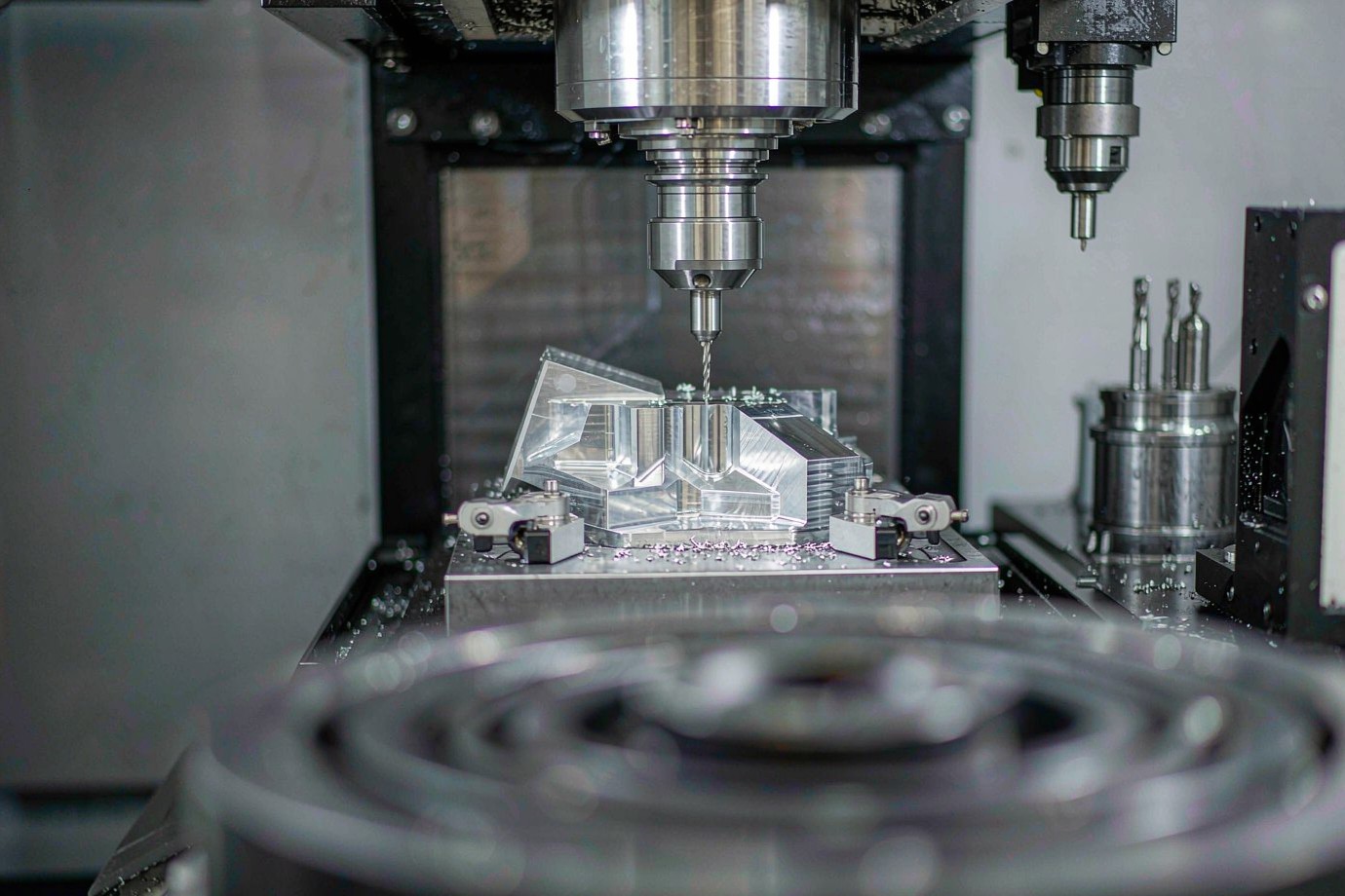
Before sending a CAD file for quotation, run a fast check on the ten areas below. Each is a common source of machining effort, added cost or rework. A "no" answer is not a failure — it is a prompt to ask an engineering question before production.
| Design Area | Quick Check |
|---|---|
| Internal Corners | Is the radius compatible with standard cutting tools? |
| Wall Thickness | Is the wall rigid enough for machining and fixturing? |
| Deep Features | Can the cutting tool reach the required depth? |
| Holes | Are hole diameter and depth practical for standard tooling? |
| Threads | Is the thread size and depth appropriate? |
| Tolerances | Are tight tolerances limited to functional features? |
| Workholding | Can the part be securely fixtured? |
| Setups | Can the design be machined with fewer setups? |
| Material | Is the material appropriate for the function and process? |
| Finish | Is the specified finish actually necessary? |
What Is CNC DFM?
CNC Design for Manufacturability (DFM) is not a list of fixed rules to memorise. It is a way of reviewing a part before production so that geometry, tolerances, material and finish match the way a CNC machine actually cuts metal. The goal is to preserve functional requirements while removing unnecessary manufacturing effort — not to make every part trivial to machine.
Most machining problems trace back to a small set of questions: can a round cutter reach the feature, can the part be held steady, how many times must it be repositioned, and which dimensions actually carry function? Answering those questions early is what separates a smooth quote-and-build from a costly revision loop.
A practical DFM decision path asks, in order: does the feature have a functional requirement → what tolerance is actually required → can a standard tool reach it → can the part be fixtured → are extra setups necessary → final review. That sequence is the backbone of the checklist later on this page.
Why DFM Matters
Design choices made in CAD translate directly into machine time, inspection and risk. Four consequences show up on every CNC program:
Cost
Smaller tools, extra operations, special tooling and added inspection all raise the price. Many cost increases come from features that were never functionally required.
Lead Time
More setups, longer cycle times and revision loops extend delivery. A clean design often ships earlier simply because nothing has to be re-engineered.
Quality
Thin unsupported walls, poor fixturing and over-tight tolerances increase variation and scrap. DFM protects the dimensional result.
Machining Risk
Deep cavities, hidden geometry and hard-to-hold shapes raise the chance of tool breakage or deflection. Surfacing these risks before production avoids surprises.
The 5 Main DFM Drivers
Nearly every CNC DFM issue falls under one of five drivers. When a quote looks high, it is usually one of these working against the design.
| Driver | What it controls | Typical effect when ignored |
|---|---|---|
| Geometry | Corner radii, walls, pockets, undercuts | Smaller tools, more operations |
| Tolerance | Which dimensions are tight | More process control and inspection |
| Part Size | Stock, machine envelope, fixture | Machine or fixture limits |
| Material | Cutting load, tool wear, parameters | Slower machining, higher tool cost |
| Surface / Appearance | Finish specification | Secondary processing |
Internal Corner Radii Rule 01
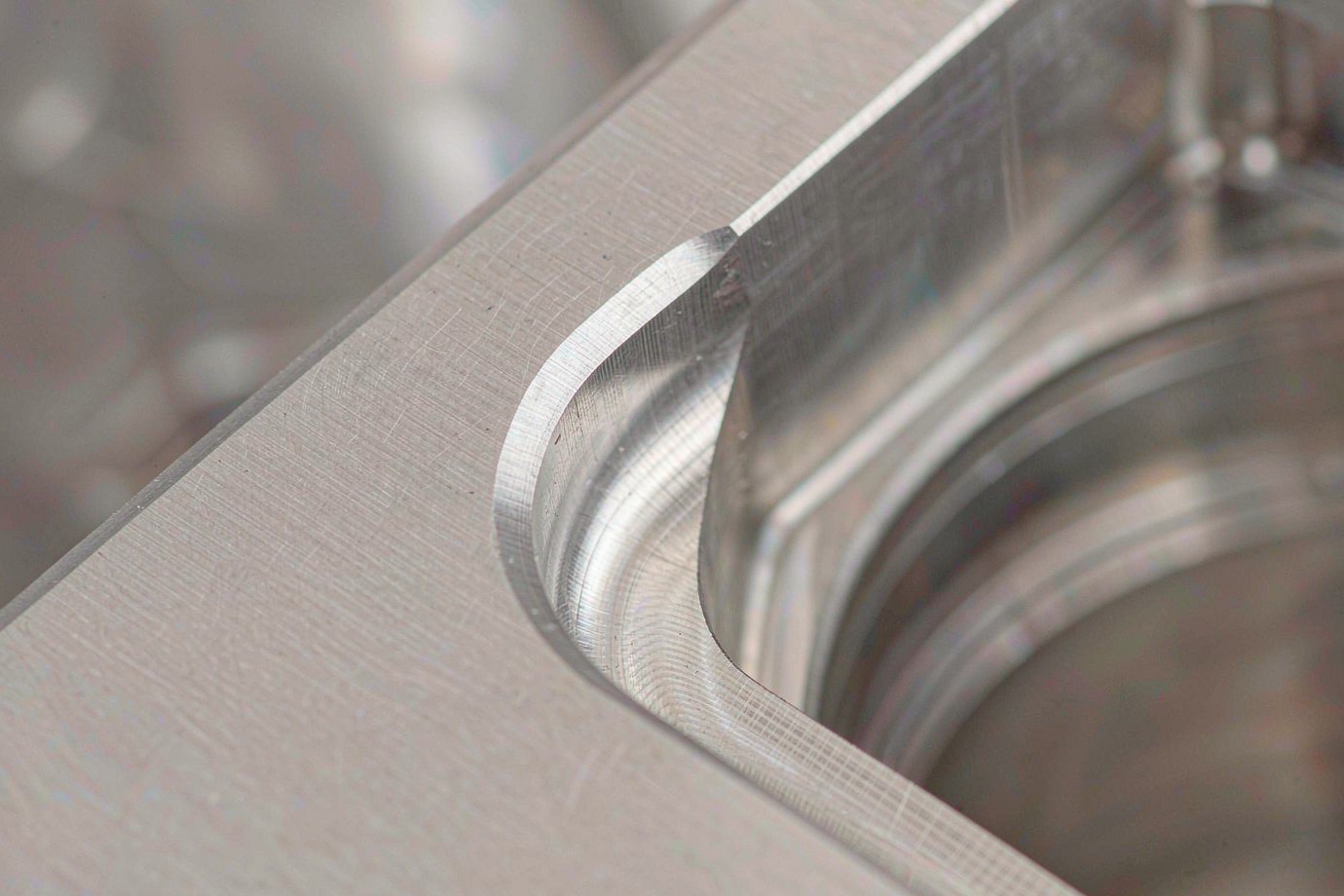
Design issue. A sharp 90° internal corner cannot be produced directly by a conventional round cutting tool — the cutter is round, so a zero-radius vertical internal corner is physically unreachable.
Manufacturing effect. Forcing a sharp corner means a smaller end mill, which increases tool deflection, machining time and tool wear, and can leave a corner that still does not match the drawing.
Better design. Use an internal radius compatible with the selected cutter whenever the function permits. The exact radius depends on tool diameter, pocket depth, material, geometry and required tolerance — it is a joint decision, not a fixed table value.
Engineering question. Does this corner actually need to be sharp, or does a functional fillet satisfy the requirement?
Wall Thickness Rule 02
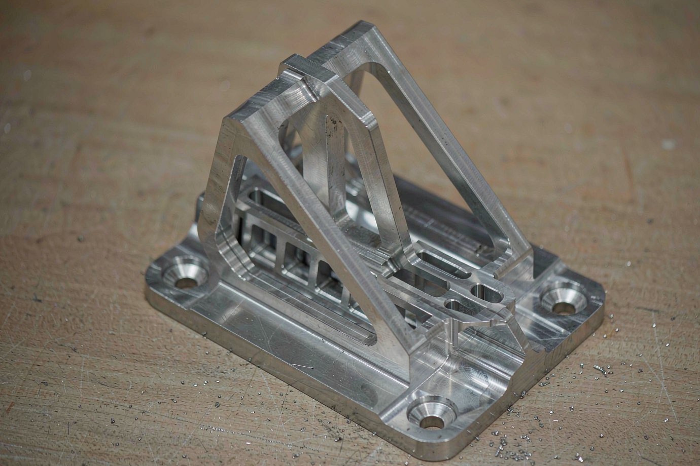
Wall thickness is one of the most mis-stated CNC topics. A single "minimum wall = X mm" number is misleading because the real limit depends on material, wall height, aspect ratio, feature accessibility, workholding and required tolerance. Thin walls flex under the cutter, vibrate, and hold wider tolerances poorly.
As a Goldcattle capability reference rather than a universal rule, thin-wall programs are routinely held at roughly 0.8 mm for aluminium, 0.5 mm for stainless steel and 0.4 mm for titanium under supported conditions. Actual feasibility is confirmed per project against geometry and fixturing. For a deeper dive, see our thin-wall CNC parts solution.
Deep Features & Tool Access Rules 03–04
Rule 03 — Deep Pockets
Three factors decide whether a pocket is easy to machine: tool reach (a short tool cannot reach deep), tool deflection (a long tool deflects and chatters), and chip evacuation (deep narrow cavities are hard to clear). Do not design depth in isolation from width and tool diameter. As a common reference, pocket depth near four times the pocket width is worth reviewing for reach and chip clearance.
Rule 04 — Tool Access & Reachability
Whether a surface can be cut depends on cutting direction, surface normal, tool length, tool diameter, collision clearance and fixturing. This is a geometric constraint first and a machine-capability question second. The sketch below shows the difference between an accessible pocket and a hidden one.
Holes & Threads Rules 05–06
Rule 05 — Holes
Prefer standard drill diameters and depths that suit standard tooling. Through holes are generally simpler than blind holes (no pecking to a bottom and no drill-point relief). Consider drilled versus interpolated holes, hole spacing, and chip evacuation. Non-standard diameters add special tooling and extra operations.
Rule 06 — Threads
Use standard sizes and practical tap depth with relief. European and North American drawings often mix metric and UNC/UNF threads, so confirm the standard before quoting. Deep threads, blind-hole taps and missing relief all add machining effort.
| Thread factor | DFM consideration |
|---|---|
| Size | Standard metric / UNC / UNF preferred |
| Depth | Practical tap depth; avoid very deep blind threads |
| Blind hole | Provide drill-point relief at the bottom |
| Access | Confirm the tap can reach and clear chips |
Tolerances Rule 07
Tolerance should be functional, not decorative. A typical CNC general tolerance is around ±0.01 mm; tighter values such as ±0.005 mm are reserved for qualified functional features, not applied across the whole drawing. Over-tolerancing a cosmetic or non-mating surface adds inspection and process cost with no benefit to the part.
| Requirement | DFM consideration |
|---|---|
| General dimensions | Use a reasonable general tolerance |
| Fit | Define the functional tolerance |
| Bearing / locating | Define the critical geometry |
| Assembly | Specify the mating requirement |
| Cosmetic feature | Avoid an unnecessary tight tolerance |
| Non-critical dimension | Do not over-tolerance |
Workholding & Setup Count Rules 08–09
Rule 08 — Workholding
A part must have a stable, repeatable datum and enough clearance for a vice or fixture. Missing flat surfaces, thin flanges that deflect in a vice, and non-parallel features increase setup complexity and process risk. Designing for secure fixturing is as important as the cutting itself.
Rule 09 — Number of Setups
More setups mean more handling, more alignment, and more opportunities for variation. Align features to common datums, create accessible machining faces, and group features by setup. Fewer, well-planned setups reduce both cost and variation.
3-Axis vs 3+2 vs 5-Axis Rule 10
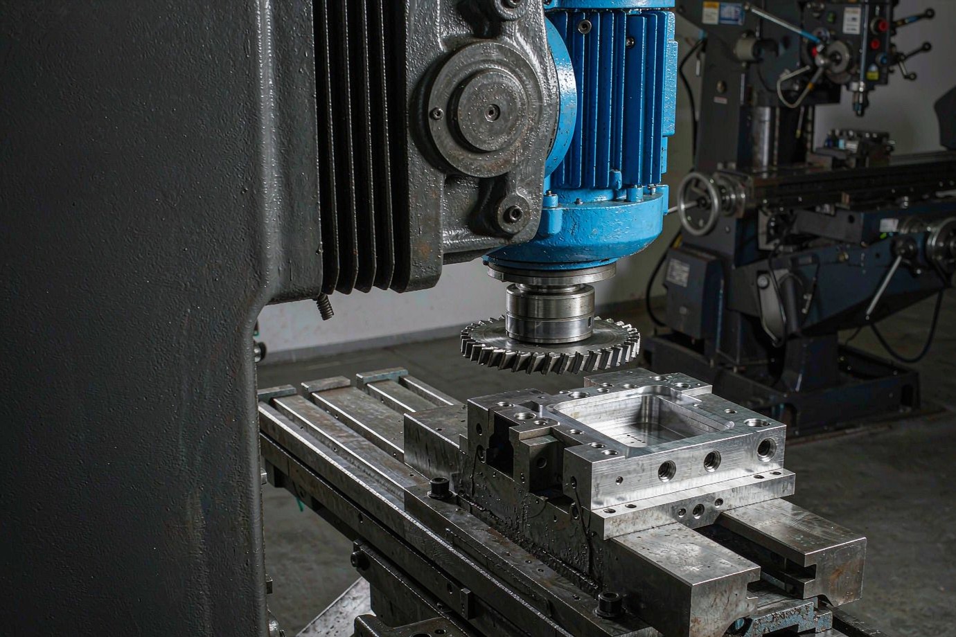
5-axis machining is not automatically better. Use the simplest strategy that meets the functional requirement. 3-axis suits simple prismatic parts; 3+2 suits multiple angled faces; full 5-axis suits complex compound surfaces and deep multi-side features. Adding 5-axis where 3-axis is enough raises complexity without improving the part. Goldcattle runs 3, 4 and 5-axis milling — see 5-axis CNC machining services.
| Geometry | Likely strategy |
|---|---|
| Simple prismatic part | 3-axis |
| Multiple angled faces | 3+2 |
| Complex compound surfaces | 5-axis |
| Deep multi-side features | 4 / 5-axis may help |
| Very high complexity | Engineering review |
Material & Surface Finish Rules 11–12
Rule 11 — Material Selection
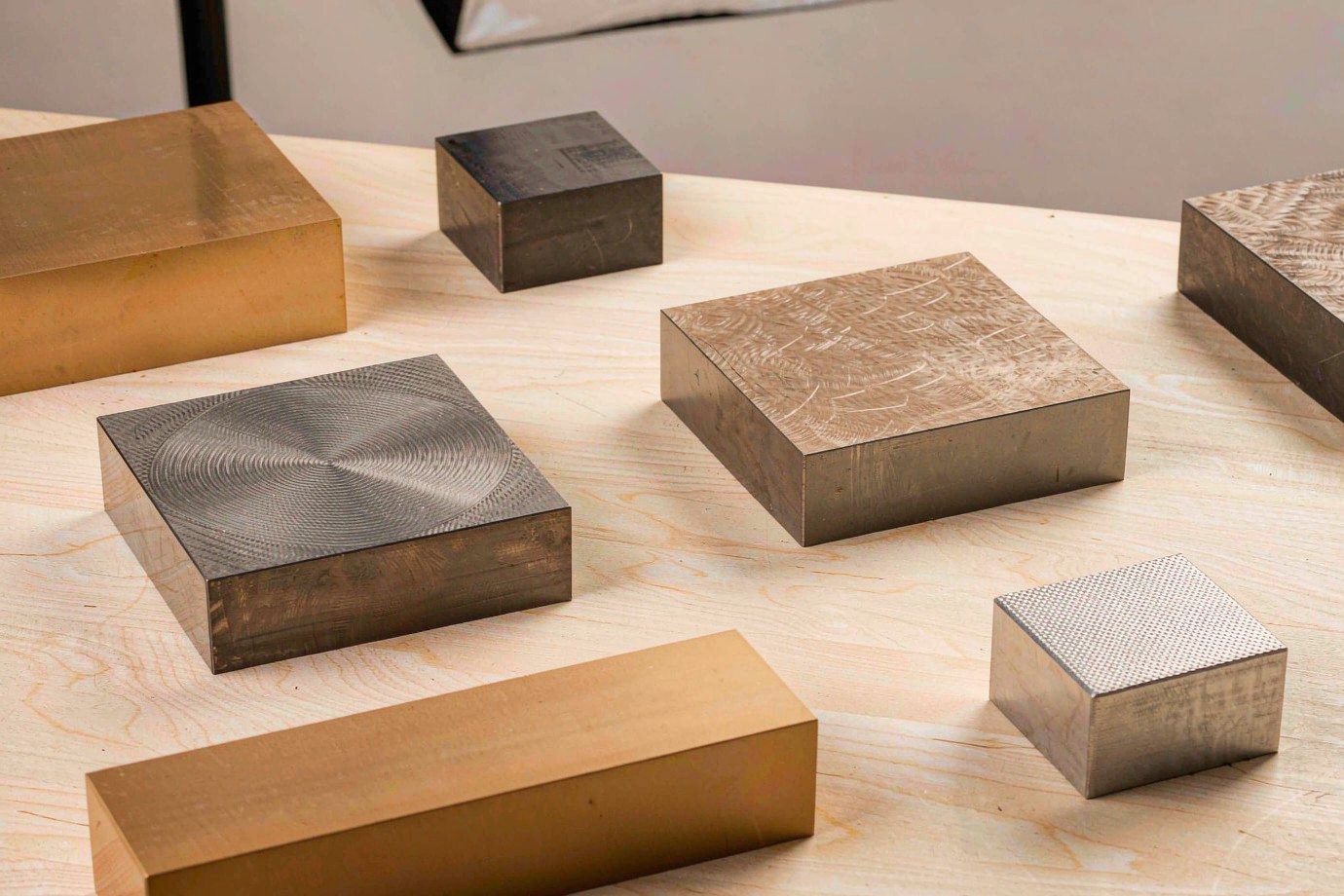
Material choice drives cutting load, tool wear, cycle time and cost. Aluminium 6061-T6 machines easily; 7075-T6 is stronger but more demanding; stainless steel raises cutting load and tool management; titanium needs careful thermal and tool management; engineering plastics need attention to deflection and clamping. Choose the material for function, then design around its machinability.
Rule 12 — Surface Finish
As-machined is often sufficient. Specify a finer finish (for example Ra 0.8 µm), polishing, anodizing or plating only when the function or appearance requires it — each adds machining or secondary processing. Question finishes that could be achieved another way before locking the drawing.
CNC DFM Cost Impact Matrix
The same design decision can move cost, lead time and quality at once. This matrix connects common design choices to their likely manufacturing effect — the basis of the "remove unnecessary effort" principle.
| Design Choice | Possible Manufacturing Effect |
|---|---|
| Sharp internal corners | Smaller tools / extra operations |
| Deep pocket | Longer tools / slower cutting |
| Thin wall | More vibration / deformation risk |
| Tight tolerance | More process control / inspection |
| Complex orientation | More setups / 4–5 axis machining |
| Custom hole size | Special tooling / additional operations |
| Deep thread | Additional machining effort |
| Excessive surface finish | Secondary process |
| Difficult material | Higher tool wear / slower machining |
| Poor workholding | Custom fixture / process risk |
Before / After DFM Case Study
The example below is built from the kind of issues a real DFM review surfaces. Figures are illustrative of typical outcomes, not a guaranteed quote — every project is confirmed against its own geometry and material.
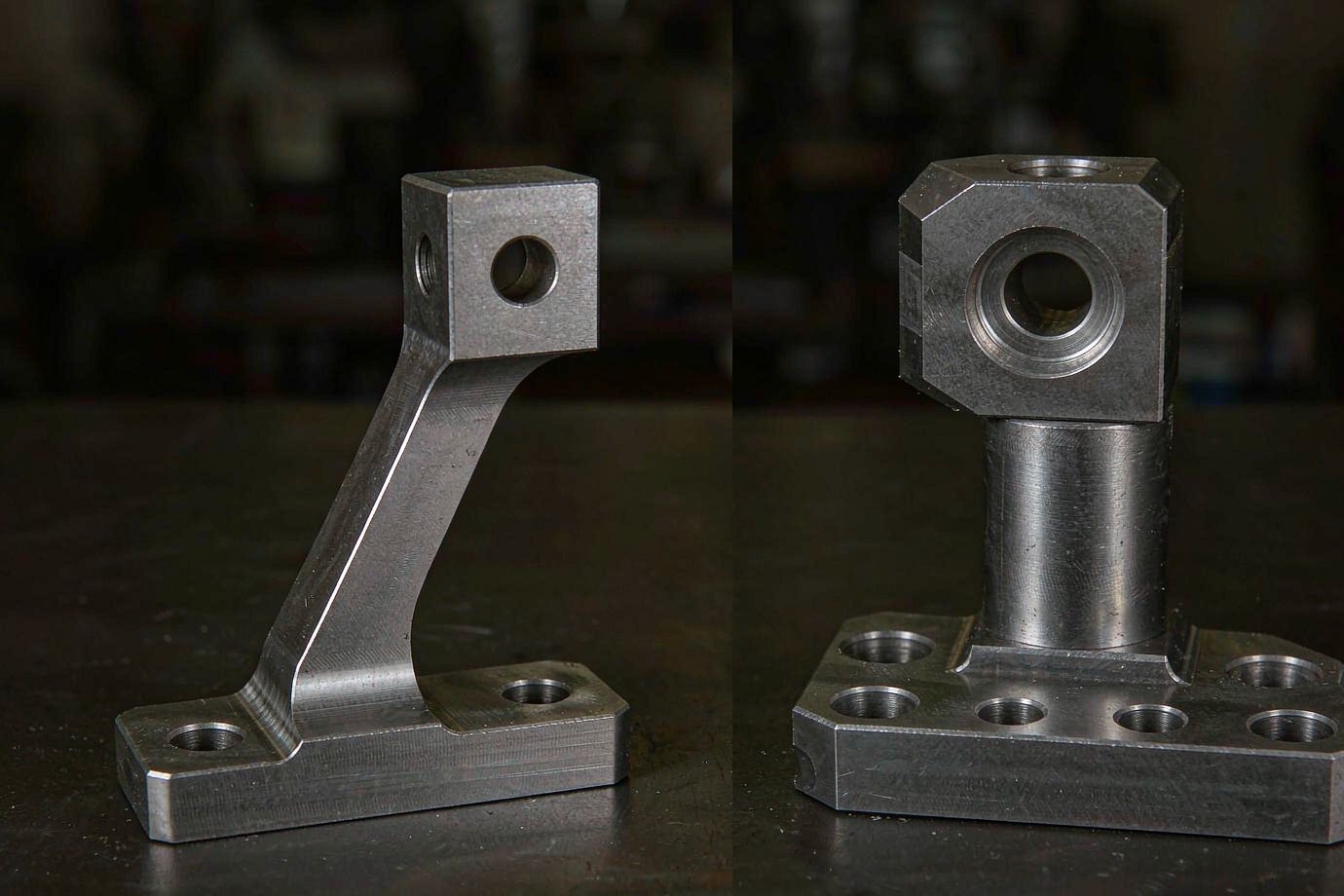
Before. Sharp internal corners, a deep narrow pocket, an unsupported thin wall, tight tolerances on non-functional surfaces, and features spread across multiple orientations.
DFM review. The engineer identified cutter-access limits, tool deflection, a fixturing weakness, unnecessary tolerances and extra setups.
After. Internal radii matched to standard cutters, the pocket width/depth rebalanced, a rib added for wall support, tight tolerances limited to mating features, and features grouped to fewer setups.
- Typical machining timereduced through fewer operations
- Setupsconsolidated to a shared datum
- Quotationmore stable, fewer open questions
- Scrap risklower via supported walls
CNC DFM Review Service
Send the 3D CAD model and 2D drawings and our engineering team will review machining access, tolerances, wall thickness, workholding, machining strategy and other manufacturing risks before production. The review is returned with the quotation.
What a DFM review checks
| Review Area | What we check |
|---|---|
| Geometry | Manufacturability of features |
| Tool Access | Cutter reach and collision |
| Internal Radii | Tool compatibility |
| Walls | Rigidity and deformation risk |
| Holes / Threads | Tooling and depth |
| Tolerance | Functional vs unnecessary tight tolerances |
| Setups | Machining orientation |
| Fixturing | Workholding |
| Material | Machinability |
| Finish | Need vs added processing |
| Part Size | Machine / stock / fixture constraints |
Example DFM findings
Internal pocket
R0 corner requires smaller tooling and an extra operation. Increase the internal radius to R2.0 mm where function allows. Status: approved by customer.
Wall
Thin unsupported section risks deflection during machining. Add a rib or increase wall thickness on the supported edge. Status: approved.
Tolerance
±0.005 mm applied to a non-functional surface adds inspection effort. Tighten only the mating feature. Status: approved.
Review process
Upload
Send CAD (STEP/IGES) and 2D drawings.
Engineering Review
Check access, tolerance, walls, fixturing, strategy.
DFM Findings
List issues with severity and effect.
Recommended Changes
Propose geometry options that keep function.
Quote / Production
Return findings with the quotation.
| DFM Issue | Severity | Meaning |
|---|---|---|
| Unnecessary ±0.005 mm tolerance | Medium | May increase machining + inspection cost |
| R0 internal corner | Medium | Smaller tool / extra operation |
| Extremely thin unsupported wall | High | May cause manufacturability or quality risk |
| Deep narrow cavity | High | Tool reach and chip evacuation risk |
| No usable fixturing surface | High | Custom fixture / process risk |
| Non-functional cosmetic finish | Low–Medium | Adds secondary processing |
Prototype vs Production DFM
The best DFM for a prototype is not always the best for production. Prototype DFM favours speed and validation; production DFM favours repeatability, cost, setup and inspection. The same part can justify different choices at each stage, because every unnecessary step keeps costing across the whole run. Where a design will scale, invest the DFM effort early. For the broader capability, see CNC machining services and instant CNC quote.
Material-Specific DFM
Aluminium 6061 / 7075
Easy to machine; watch heat at thin sections. 7075 needs firmer parameters. Reference thin-wall ~0.8 mm under support.
Stainless Steel
Higher cutting load and work-hardening; plan tool wear and rigidity. See stainless steel CNC. Reference thin-wall ~0.5 mm.
Titanium Grade 5
Heat and tool management matter; 5-axis helps access. Reference thin-wall ~0.4 mm. See Ti-6Al-4V machining.
Steel & Brass
Steel varies widely by grade; brass machines freely but needs secure clamping to avoid movement.
Engineering Plastics
PEEK and similar need care with deflection, clamping and heat; avoid trapping stress in the fixture.
Process-Specific DFM
Milling
Most DFM rules above apply: radii, walls, pockets, access, setups and fixturing.
Turning
Favour round symmetry; consider part length-to-diameter for chatter and tailstock support.
5-Axis
Improves access to compound surfaces; still design for fewer flips and clear collision.
Turn-Mill
Combine operations in one hold to cut setups; keep features reachable from the driven tools.
CNC DFM Checklist
Goldcattle uses a consistent review order so nothing is missed. Walk the part through these eight steps before releasing the drawing:
| Step | Check |
|---|---|
| 1 · Geometry | Features are reachable by a round cutter; no impossible sharp corners. |
| 2 · Tool Access | Clear approach and collision clearance for every surface. |
| 3 · Fixture | Stable datum and clamping clearance exist. |
| 4 · Setup | Features grouped to the fewest orientations. |
| 5 · Tolerance | Tight values limited to functional features. |
| 6 · Material | Material suits function and is machinable on hand. |
| 7 · Finish | Each finish is actually required. |
| 8 · Inspection | Critical dimensions are measurable and documented. |
Frequently Asked Questions
What is DFM for CNC machining?
Why do CNC parts need internal corner radii?
What wall thickness is recommended for CNC machining?
How does tolerance affect CNC machining cost?
How does 5-axis machining affect DFM?
How does workholding affect CNC part design?
How deep can a CNC pocket be?
How should holes and threads be designed?
What does a CNC DFM review include?
Can a CNC manufacturer review my CAD before quoting?
How can I reduce CNC cost through DFM?
Need a Manufacturability Review?
Send us your CAD model and drawing. Our engineering team will review machining access, tolerances, wall thickness, workholding and strategy before production — and return findings with your quotation.
Upload CAD for DFM Review Or get an instant CNC quote →Reviewed drawings typically return DFM feedback with the quote — usually within one business day.