Insert Molding Services: Metal Inserts Molded Into Your Part
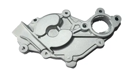
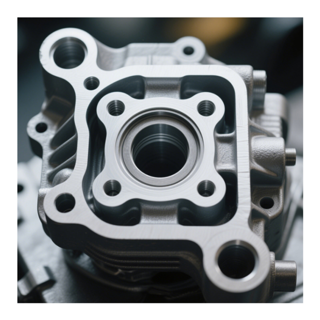
Insert molding places prefabricated metal or plastic inserts into the mold so the plastic forms around them — producing a single component with threads, bushings, terminals or reinforcements fixed in position, without a separate installation step.
From DFM review and retention design to tooling, insert handling and verified production, this page explains what determines insert molding quality: how the insert is located and held, how retention is engineered, and how position and performance are verified before the run starts.
The RFQ checklist on this page is shown in full. Select the text to reuse it, or use your browser's print / save-as-PDF — Goldcattle does not host downloadable files on this site.
What Is Insert Molding?
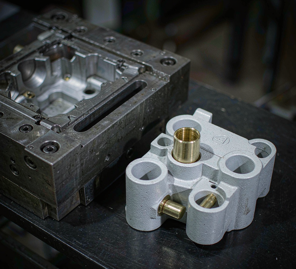
Insert molding fixes a prefabricated insert inside a molded plastic part in a single operation: the insert is placed and held in the mold, the resin is injected around it, and the finished component leaves the mold with the insert permanently positioned.
The engineering value is not that plastic "sticks to" metal. It is that the insert ends up in a defined position, with a defined retention structure, batch after batch — and that the separate steps of installing inserts after molding disappear from the assembly line.
Insert molding
The insert is molded into the part during the shot. Position is set by the mold, not by an assembly operator, and the retention structure is engineered around the insert geometry.
Post-installed inserts
Heat-set, ultrasonic, press-in or self-tapping inserts are installed after molding. Tooling is simpler and drawing changes are cheaper early — but each part passes through an extra operation with its own position variation and labor cost.
Overmolding
A different problem: bonding a soft or second material over a rigid substrate. Some parts need insert molding and overmolding together — a multi-step or two-shot process. Insert molding vs overmolding compares the two.
Insert Types We Mold
Four insert families cover most projects — each with its own design focus. The insert type, material and supply route are confirmed per project during engineering review.
Threaded inserts
For repeatable threaded connections in plastic housings, brackets and equipment enclosures. Design focus: thread specification, insert length, knurl pattern and the surrounding plastic structure that resists rotation and pull-out.
Bushings and sleeves
For mounting, guidance, wear resistance or local load bearing. Design focus: fit dimensions, load path through the plastic, wear expectations and the wall thickness around the insert.
Terminals and contacts
For electrical connectors and related plastic components. Design focus: insert position accuracy, insulation structure, in-mold locating during the shot, and the electrical verification your specification requires.
Pins and reinforcement inserts
For locating, local reinforcement or a specific metal function in the assembly. Design focus: retention structure, load transfer into the plastic, thermal expansion mismatch and molding stability.
Insert Design and Retention Engineering
Insert retention is an engineering result, not a material property: it comes from the insert geometry, the plastic structure around it, the molding process and the load the part actually sees.
Industry engineering data is consistent on this point — insert performance depends not only on the insert itself, but on the plastic material and its fillers, the part design, and hole and installation quality. That is why we review retention with you before tooling, rather than after the first parts fail.
- Locating during molding: mold features that hold the insert against plastic flow, so it does not shift or tilt during injection.
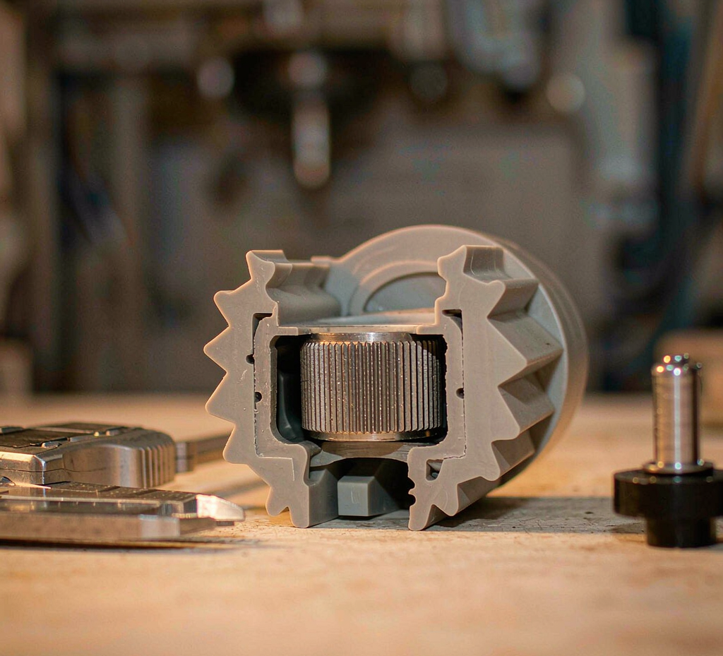
- Retention structure: knurl, flanges, grooves or undercuts that transfer load into the surrounding plastic.
- Surrounding wall and boss: wall thickness and boss geometry sized for the load path — too thin cracks, too thick sinks.
- Thermal expansion: the metal-plastic mismatch across the service temperature range.
- Molding stability: flash control, insert temperature at fill, and the effect of filler content on brittleness around the insert.
Engineering verification matrix
Five checks answer whether the molded insert meets the design. Each should have a defined method and acceptance criteria before tooling — not after.
| Verification | Question it answers | Recommended method |
|---|---|---|
| Insert position | Is the insert off-position, tilted or outside the drawing's permitted deviation? | Measure position, orientation and protrusion against the drawing datum. |
| Pull-out resistance | Will the insert be pulled out under axial load? | Axial pull-out test per your application and agreed requirements. |
| Rotational torque | Will a threaded insert rotate when tightened or under reverse torque? | Torque test under defined conditions, with the test definition and failure criteria agreed in advance. |
| Pull-through resistance | Can a flanged insert be pulled through the surrounding plastic? | Verify against the part's actual load directions and structural needs. |
| Crack / boss integrity | Does the plastic around the insert crack or fail locally? | Visual inspection, section analysis where needed, and mechanical testing. |
What we will and will not claim
No supplier can promise "firm insert retention" without knowing the load. What a project needs is defined: your actual load and torque requirements, the structure and molding factors that affect them, and the test that proves the finished part passes. We define that verification set with you before tooling, and document the results in the first-article inspection report.
Insert Materials, Resins and Supply Route
Insert material, resin and who supplies the insert are all project decisions — each is confirmed during engineering review, not assumed from a standard list.
| Item | Typical options | What to confirm |
|---|---|---|
| Insert material | Brass, stainless steel, carbon steel, aluminum, engineered plastics. | Grade, finish and any plating — matched to the load, environment and assembly torque. |
| Insert supply route | Supplied with tooling, or free-issued by you. | Who buys the inserts, incoming inspection responsibility, and lead-time impact on the mold trial. |
| Plastic resin | ABS, PP, PE, PC, PA, POM, TPU, PEEK, PPS and most glass- or mineral-filled thermoplastics. | Grade and filler content against load, temperature and the retention structure — filler content changes brittleness around the insert. |
When Insert Molding Is the Right Choice — and When It Isn't
Insert molding is not automatically the cheapest route. The honest comparison weighs tooling investment, piece cost, insert installation cost, defect risk, assembly labor and lifecycle cost against your volume and design stability.
| Project situation | Compare with | Why |
|---|---|---|
| Low volume, drawings still changing | Molding separately, then post-installing inserts | Avoids early mold rework when the design is not yet stable. |
| Simple, low-load threaded connection | Heat-set, ultrasonic or press-in inserts | Mature post-install methods may avoid the in-mold positioning step entirely. |
| High volume, stable insert position and performance requirements | Insert molding | Removes a separate installation and assembly operation, with position set by the mold. |
| Metal insert plus soft grip or seal on the same part | Insert molding combined with overmolding or two-shot | Evaluate process sequence, mold structure and the verification each step needs. |
The decision rule: if volume is stable and the insert position is critical, in-mold placement usually pays for itself. If volume is low or the design is still moving, the cheaper tool and post-installed insert is often the lower-risk start. We will say which route we believe fits — even when it is not the higher-value one for us.
Quality Verification and Traceability
An insert-molded program is verifiable when position, retention, material and process are each documented — from incoming insert to shipped part.
Design and tooling stage
DFM review of the retention structure and insert locating; mold validation with insert position measured to the drawing datum before production release.
Verification stage
First-article inspection with the agreed test set — position, pull-out, torque and any structural checks — with methods and acceptance criteria defined before the trial.
Production stage
In-process and final inspection, material certificates tied to the batch, and documented process records — so a shipped part can be traced back to its insert lot, resin lot and inspection results.
Inspection capability spans CMM, gauges and first-article reports under our ISO 9001:2015 quality system; the exact verification set for your part is agreed in the quality plan at quotation. Tolerances for molded features are defined per drawing and confirmed at mold validation — mold machining accuracy, plastic part tolerance and insert position tolerance are separate specifications and are treated separately.
Tooling and Project Milestones
An insert molding project moves through five gates. Each gate has a deliverable, and the schedule is confirmed at quotation — not promised in advance.
Retention structure, insert locating, resin and verification set reviewed against your drawing.
Tooling manufactured in-house, including the features that locate and hold the insert.
Trial shots with the actual insert; position, flash and molding stability checked.
First-article inspection with the agreed retention tests; your written approval before volume.
Stable runs with in-process checks, batch traceability and documented delivery.
Typical mold lead time for standard tools is 3–6 weeks; multi-cavity or multi-step tools take longer, and insert supply can sit on the critical path if you free-issue the inserts. The staged schedule with each gate's date is confirmed in the quotation.
What to Send With Your Insert Molding RFQ
A complete RFQ gets an accurate quotation faster. Eight items cover what engineering needs to assess tooling, retention and verification.
| Item | What to include |
|---|---|
| Part function and assembly | What the insert does in the assembly — thread size, bearing, guidance, electrical or locating function. |
| Insert specification | Insert type, material, grade, dimensions and who supplies it — us or free-issued by you. |
| Load requirements | Pull-out, torque or electrical requirements if defined — these drive the retention design and the test set. |
| Plastic material | Resin grade, color and filler content, or the requirement the material must meet. |
| Volume | Annual quantity, program life and batch plan. |
| Drawings | 3D CAD and 2D drawings at a named revision (STEP, IGES, STL, DWG, DXF or PDF). |
| Tolerance and verification | Critical dimensions, insert position tolerance, inspection requirements and report type. |
| Timeline | Target dates for samples, validation and production start. |
Frequently Asked Questions
What is insert molding and when is it used?
Insert molding places prefabricated inserts — metal or plastic — into the mold before or during the shot, so the plastic forms around them and the insert is fixed in place as a single component. It is used when a part needs a threaded connection, bushing, terminal or reinforcement that must stay accurately positioned through production volume, removing separate installation and assembly steps.
What insert materials can be molded in?
Common insert materials include brass, stainless steel, carbon steel, aluminum and engineered plastics. The insert material and supply route — supplied by us or free-issued by you — are confirmed per project during engineering review, together with the resin and any filler content.
How is insert position and retention verified?
Insert position is measured against the drawing datum and permitted deviation. Retention is verified through tests agreed with you before tooling — typically axial pull-out and rotational torque tests with defined methods and failure criteria, plus pull-through or crack checks where the structure requires them. Results are documented in first-article inspection reports.
What is the difference between insert molding and overmolding?
Insert molding fixes a prefabricated insert inside the plastic; overmolding bonds a second material — usually a soft TPE or TPU layer — over a rigid substrate. Some parts need both, which becomes a multi-step or two-shot process. See our insert molding vs overmolding comparison for the selection criteria.
Who owns the mold, and are drawings protected?
The mold is your asset. We store and maintain it and can ship it to you on request. NDAs are signed before drawings are exchanged, and your design files and tooling are not reused or shared with third parties.
What files do you need for an insert molding quote?
3D CAD and 2D drawings at a named revision (STEP, IGES, STL, DWG, DXF or PDF), plus the resin preference, insert specification, estimated annual volume and target timeline. Insert load or torque requirements, if defined, make the quotation more accurate.
Planning a part with molded-in inserts?
Send the drawing, insert specification and load requirements. Our engineering team reviews the retention structure and locating design, confirms the verification set with you, and quotes tooling and production with the schedule staged by gate.
- DFM review of insert retention and locating before tooling
- Agreed verification set — position, pull-out, torque — defined before the trial
- FAI approval and batch traceability before volume production

Reviewed this page on 2026-10-19. Verification methods and retention design follow general insert-molding engineering practice; the test set, tolerances and schedule for your part are defined per project at quotation and confirmed at mold validation. Technical and commercial questions are answered within 24 hours.