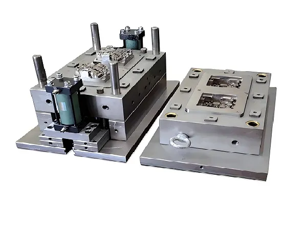
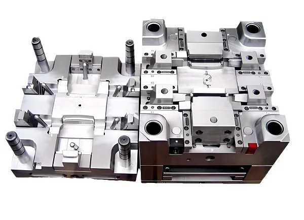
Injection Moulding · Programme Management
Prototype to Production: The Seven Gates an Injection Moulding Programme Has to Pass
Moving a part from a prototype to repeat production is not a timeline. It is a series of gates, and each one asks for evidence rather than a date. Most programmes that fail between the two did not fail in production — they passed a gate without the evidence it requires.
This page is about the gates and their exit criteria, not about what the plant can do. Capability figures live on the injection moulding services page; tool design lives on the mould page.
What This Page Decides, and What It Leaves to the Other Pages
The commercial question behind this topic is usually phrased as "can one supplier take me from prototype to production?" The useful version of that question is narrower: at each stage, what do I receive, and what has to be true before the next stage starts? A supplier who can answer that for your part is doing programme management. A supplier who answers with a list of machines is selling capacity.
This page covers the seven gates, the evidence each one produces, and the decisions that are hard to reverse once they are made. It does not re-describe the moulding process envelope, tool steel selection or the mould construction sequence; those sit on their own pages and are linked at the end rather than restated here.
The Seven Gates, and What Each One Has to Produce
| Gate | Decision that closes here | Evidence produced | What it costs to skip |
|---|---|---|---|
| 1 Requirements and design freeze | Which revision is being quoted and tooled, and which requirements are still open | Frozen drawing revision, critical-to-quality list, open-items register | Tool cut to a superseded model; every later change becomes a steel change |
| 2 DFM and route selection | Which manufacturing risks are accepted, and which tooling route is being bought | DFM report with dispositions, route recommendation, risk list | Risks discovered at T1, when corrections cost tool time instead of screen time |
| 3 Prototype and design validation | Whether the design works, and which characteristics the prototype could not test | Dimensional, fit, function and appearance records with open issues listed | A prototype sign-off treated as a production sign-off |
| 4 Tool build and trials | Whether the tool can make the part at all, then whether it makes it to drawing | T0 feasibility record, T1 dimensional and cosmetic results, correction log | First shots shipped as if they were production parts |
| 5 Sample approval | Which sample is the reference, and on which characteristics | Signed approval against a named sample, with toleranced and cosmetic limits | Two parties remembering two different samples six months later |
| 6 Pilot run and readiness | Whether the process repeats, not just whether it can | Pilot quantity, yield, inspection results, process records | A first batch that passes and a second that does not |
| 7 Production release | What is frozen for the life of the programme, and what triggers re-qualification | Released specification set and a change-control rule | Silent drift: resin swap, tool repair, re-polish, new subcontractor |
Gate 1: What a Design Freeze Actually Freezes
Most programmes do not need every detail settled before tooling. They need the irreversible details settled, and the reversible ones listed so nobody mistakes them for decisions. The table below is the split that matters in practice.
| Must be frozen before tooling | Can usually stay open past tooling |
|---|---|
| Functional requirement and the dimensions that carry it | Colour, tint and masterbatch route, where the grade is already fixed |
| Mating interfaces: what this part touches, and with what clearance | Texture or polish on non-critical faces |
| Wall thickness intent, and the features that set it | Non-critical radii and cosmetic chamfers |
| Cosmetic class per face — which faces are visible, which are hidden | Packaging, labelling and carton configuration |
| Resin family, plus any regulatory constraint on it | Branding, moulded-in marks and their position, if the tool allows an insert |
| Annual volume band and order pattern — it sets the tooling route | Minor rib or gusset additions that do not move a steel face |
| Gating policy: where the gate may and may not leave a mark | Secondary operations that happen after moulding |
Two items on the right-hand list become expensive if they are moved to the left by default. Colour is often fixed by a chip that arrives weeks later; forcing it into the gate delays tooling for no gain, as long as the resin grade is fixed and the colour is dosed at the machine. Texture is the reverse: a texture specified after the cavity is polished changes the draft requirement, and draft is steel.
Gate 2: DFM Is a Disposition Record, Not a Compliment
Findings fall into four groups, and each group is owned by a different conversation. Mixing them is why DFM feedback often reads as a list of complaints rather than a set of decisions.
| Group | Typical findings | Who decides |
|---|---|---|
| Geometry | Wall steps, rib-to-wall ratio, boss wall thickness, sharp internal corners, insufficient draft on a deep face | Product designer, with the mould maker's constraint in view |
| Mouldability | Fill balance, gate position and size, venting at the last-fill point, ejection area, undercut that needs a slide | Mould designer; the product owner confirms what may change |
| Appearance | Weld line across a visible face, sink over a boss, gate vestige on a cosmetic surface, texture that reduces gloss | Product owner, against the cosmetic class agreed at Gate 1 |
| Tooling risk | Features needing EDM or a lifter, thin steel in a core, cooling that cannot reach a hot spot, expected maintenance | Toolmaker, with cost and lead time passed back to the buyer |
What the review cannot do
It cannot find a requirement nobody wrote down. If the drawing does not say that a face is visible, the review will not protect it. It cannot confirm that the part functions — that is what Gate 3 is for. And it cannot price a change you have not decided to make, which is why a DFM report that ends in a list of open questions has not closed Gate 2.
Choosing the Tool: Four Routes, and When Skipping One Is Correct
| Route | What it is for | What it can prove | Main limit |
|---|---|---|---|
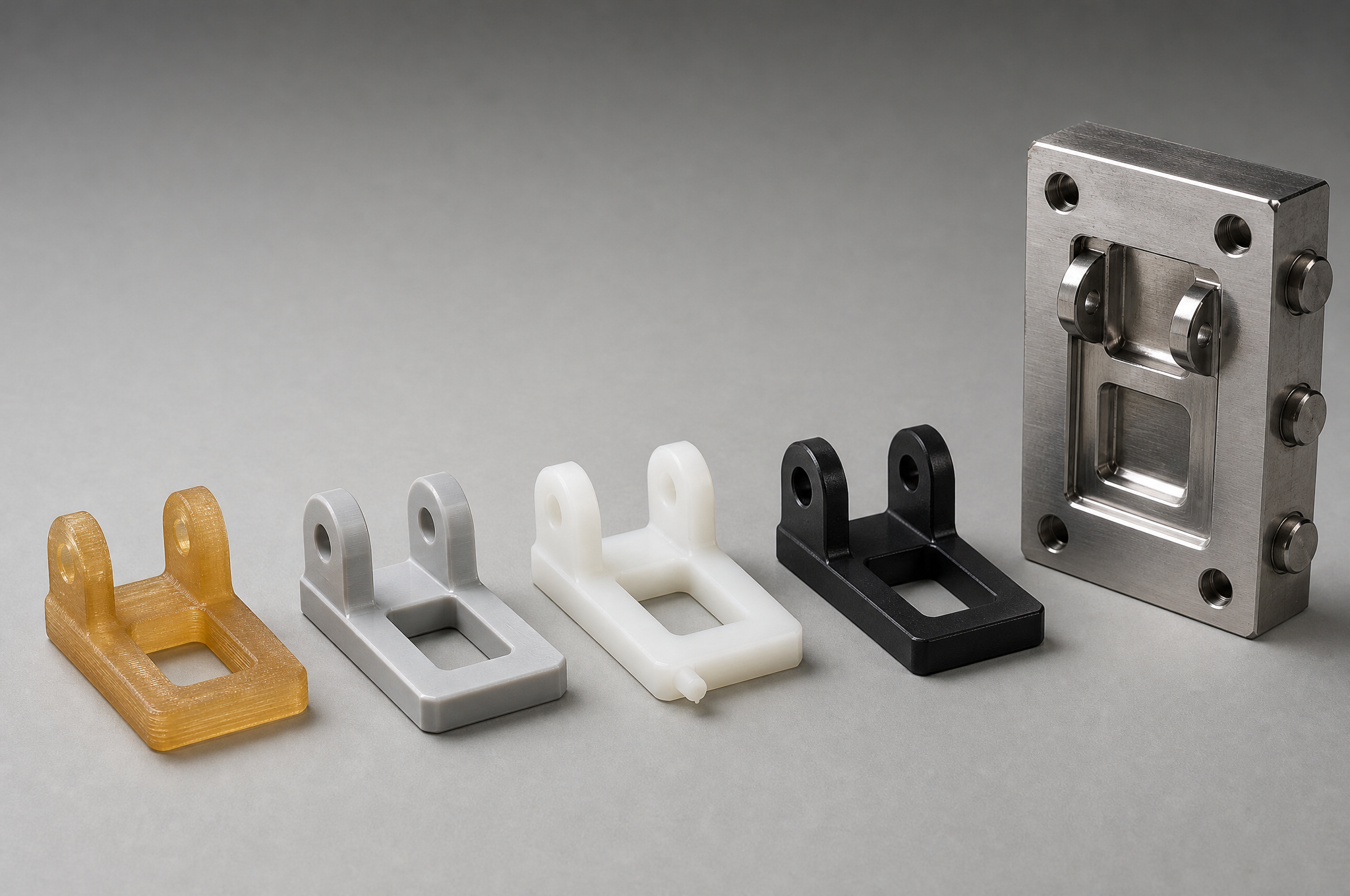
| Machined or printed prototype | Geometry, fit, early assembly studies, investor and customer samples | Shape, interfaces, some function | Not the production resin behaviour: no shrinkage, no weld line, no gate vestige, often a different material |
| Prototype tool | Moulding the part in the intended resin for real tests | Fill, ejection, basic function, material behaviour | Short life and simple construction; not built for a long production schedule |
| Bridge tool | Launch, market test or supply while the production tool is being built | Real parts in real resin at modest volume | Not intended for a long high-load campaign; its structure sets a ceiling on output and life |
| Production tool | Repeat supply over a programme of months or years | Stable output, cavity-to-cavity consistency, long life | Higher entry cost, and a design change is now a steel change |
The four questions that pick the route
How mature is the design? If a change is likely within two revision cycles, hardened steel is the wrong place to park it. What is the annual volume and the programme length? Tool cost is amortised over parts, so a two-year programme and a two-month programme do not justify the same tool. How expensive is a change? A cosmetic housing in a polished cavity is far more expensive to revise than a hidden bracket. What does the tool have to survive? Abrasive or glass-filled resin shortens life regardless of steel grade, and the tool specification has to account for the resin rather than for the part alone.
Gate 3: What a Prototype Cannot Prove
This is not an argument against prototyping. It is an argument for writing down, at Gate 3, which characteristics were tested and which were not. A prototype sign-off that lists its own blind spots is a strong document. One that says "approved" without qualification is a liability that surfaces at T1.
| Characteristic | Machined prototype | 3D-printed prototype | Moulded sample |
|---|---|---|---|
| Geometry and fit | Representative | Representative, less accurate on fine features | Representative |
| Production resin properties | Only if cut from the same grade, which is rare and wasteful | No — printing resins are a different material family | Yes |
| Shrinkage and warpage | No | No | Yes, and measurable |
| Weld lines and gate vestige | No | No | Yes, in the positions the tool creates |
| Tool texture and gloss | Only if the machined surface matches it | No — layer texture is not tool texture | Yes |
| Anisotropy and layer strength | Directional, as the stock is | Strongly directional and usually weaker across layers | As moulded, with its own flow orientation |
| Cycle economics | Not applicable | Not applicable | Yes — and this is where unit cost is decided |
| Assembly in production parts | Indicative | Indicative | Conclusive, because it is the same part |
Where this changes the plan
If the product's function depends on the resin — a snap fit that must survive repeated deflection, a seal that must compress, a part that must pass a drop or a heat test — then the test has to run on a moulded sample, and the programme needs a prototype tool rather than a printed model. If the product's function is mostly geometry — a bracket, a bezel, a spacer — a machined or printed prototype is enough, and spending on a prototype tool buys little.
Gate 4: T0, T1 and T2 Are Three Different Questions
| Trial | Question it answers | What is checked | What it is not |
|---|---|---|---|
| T0 — first trial | Does the tool fill, pack, eject and survive a cycle? | Short shots, fill balance, ejection marks, gross dimensional error, obvious tool faults | Not a sample for approval, and not evidence of dimensional capability |
| T1 — after correction | Is the part to the drawing and to the cosmetic standard? | Dimensional report on the CTQ list, cosmetic assessment against the agreed class, fit with mating parts, specified functional tests | Not yet proof that the process repeats at production conditions; the process window is still being settled |
| T2 — confirmation | Does the part hold when the process is set for production? | Repeat measurement across a run, cavity-to-cavity comparison, process parameters recorded | Not a substitute for a pilot run at the intended output rate |
What a T1 report should contain
The measured features and their results against the drawing tolerance, the cosmetic result with photographs of any deviation, the fit result with the mating part, the tool corrections made since T0, and a deviation list naming anything that is not to drawing. A T1 report without a deviation list is either a perfect part — rare on a first corrected shot — or a report that only measured the features that passed.
Gate 5: Three Approvals, Not One
| Approval | Evidence | Failure mode when it is skipped |
|---|---|---|
| Dimensional | Measured report on the agreed CTQ list, with datum and method stated | A part that assembles in the sample and does not assemble in the tenth batch |
| Cosmetic | Assessment of each face against its class, with limit samples for the borderline cases | An argument at goods-in about whether a flow mark is a defect |
| Functional | The specified test, on the specified number of parts, under the specified conditions | A snap fit that passes once and cracks on the tenth cycle |
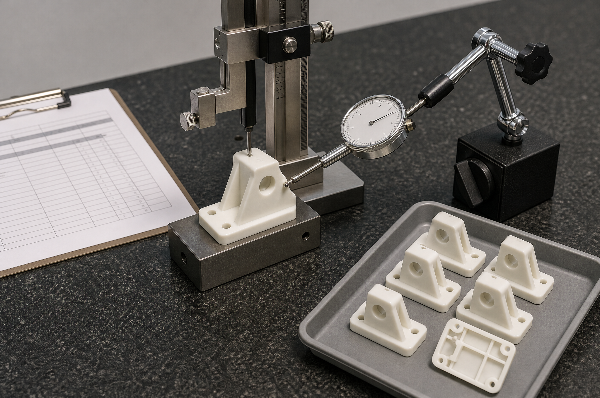
The approval record is the artefact that makes the rest of the programme stable. At minimum it should name the sample — by identifier, not by "the one we sent in March" — the drawing revision it was measured against, the resin grade and lot, the tool it came from, and any deviation that was accepted with its scope. Two parties holding the same document cannot later disagree about what was approved, which is the entire purpose.
Gate 6: A Pilot Run Proves Repeatability, Not Conformance
A pilot run is a representative batch — produced on the production tool, in the production resin, at the production cycle, on the production machine if that is already fixed. Its outputs are not only parts but numbers: yield, the spread of the critical dimensions, the rate of cosmetic rejects, and the process parameters that were actually held.
| What the pilot should produce | Why it matters more than a sample |
|---|---|
| Quantity actually run, and quantity conforming | Establishes the yield the part price was based on; a yield assumption that was never measured becomes a margin dispute |
| Critical dimensions across the run, not one part | Shows drift — tool warm-up, material lot, holding pressure decay — that a single sample cannot reveal |
| Cavity-to-cavity comparison, where the tool is multi-cavity | An unbalanced tool produces parts that pass individually and differ functionally |
| Cosmetic reject rate on the visible faces | The cosmetic class is a rate, not a promise; the pilot measures it |
| Process window and the settings held during the run | Becomes the production baseline, and the reference for judging drift later |
| Any inspection or qualification records the buyer needs | Better arranged before the run than reconstructed after it |
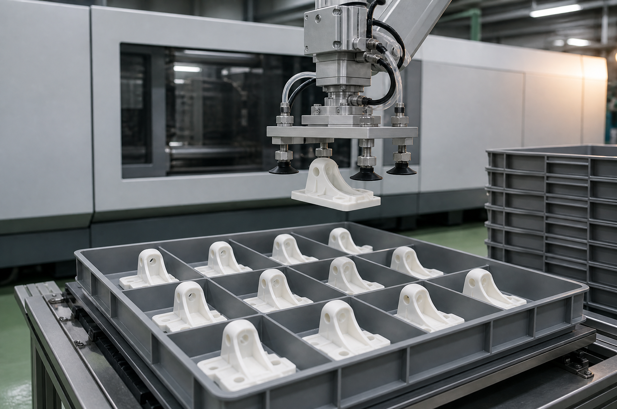
On capability studies and small runs
A capability index needs enough data to mean anything; a thirty-piece pilot cannot establish one, and a supplier who presents a capability figure from a handful of parts is presenting arithmetic rather than evidence. For small runs, the honest deliverable is conformance plus first-article data plus the parameter record — and a capability study deferred until there is a production history to study.
The depth of qualification should follow the customer and the industry. Some buyers need a formal first article; some need a full production-part approval submission; many need neither. What should never happen is a supplier implying that every programme receives the heaviest qualification, because that claim is untestable and usually untrue.
Gate 7: The Frozen Set
| Frozen item | What is recorded |
|---|---|
| Drawing revision | The exact revision, and the list of characteristics marked critical |
| Resin | Grade, supplier and any additive or colour route; substitution is a change, not a purchasing decision |
| Tool | Tool identification, cavity count, current state, and the last repair or modification |
| Process window | The settings held during the approved pilot, with the ranges that are permitted |
| Inspection plan | Characteristics, method, rate, records and the acceptance basis |
| Cosmetic standard | Class per face, plus the retained limit samples |
| Packaging and delivery | Protection, labelling, carton configuration and the delivery terms |
Once this set exists, quality assurance stops being a matter of opinion at goods-in and becomes a comparison against a document. It also gives the supplier a defensible position: a part that matches the frozen set is conforming, and a complaint that does not reference the set is a request for a change.
Approved Is Not Ready: The Eight Transfer Risks
| Transfer risk | Mechanism | Gate that should have caught it |
|---|---|---|
| Design was never actually frozen | Changes continue after tooling; each one is handled as a favour rather than a revision | Gate 1 — open-items register |
| Prototype and production are different materials | The approved part was printed or machined in a stand-in material with different stiffness and creep | Gate 3 — declared blind spots |
| Tool and process never stabilised | Gate, venting or cooling was still being tuned when the sample was signed off | Gate 4 — T2 at production conditions |
| Critical dimensions were never formally approved | Only a visual check was recorded; the CTQ list was never measured | Gate 5 — dimensional approval |
| Cosmetic standard exists only as an adjective | "Good finish" means one thing at approval and another at goods-in | Gate 5 — class per face and limit samples |
| No inspection plan at production | The pilot was inspected; the production run is not, because nobody wrote down what to check or how often | Gate 6 — inspection plan |
| Resin substitution | A grade becomes unavailable, or a cheaper equivalent is used, and the difference is invisible until a function test | Gate 7 — frozen resin |
| Silent tool change | A repair, a re-polish or a cavity replacement alters the part; no re-qualification is triggered | Gate 7 — change control |
Change Control: Which Changes Need a New Sample
| Change | Typical treatment | Why |
|---|---|---|
| Geometry change affecting a steel face | New sample approval | The tool changed, so the process that produced the approved part no longer exists |
| Resin grade or supplier change | New sample approval, plus a function check | Shrinkage, flow and mechanical behaviour all move; dimensions shift before anything visible does |
| Colour or masterbatch change | Recorded, with a colour approval | Dimensionally neutral in most cases, visually significant always |
| Tool repair or re-polish | First-article check on the affected features | Repair can restore a dimension or move it; only measurement distinguishes the two |
| Process parameter change inside the approved window | Recorded | The window exists precisely so that ordinary adjustment does not become a re-qualification |
| Process change outside the window, or a different machine | Re-qualification of the affected characteristics | Outside the window is a different process, even if the resin and tool are unchanged |
| New subcontractor for a secondary operation | Approval of the operation, not the part | Painting, printing or assembly can change appearance or fit without touching the moulding |
Mould Ownership, Possession and End of Life
The points worth having in writing are short: who owns the tool and when ownership transfers; who pays for maintenance, and what counts as normal wear against damage; where the tool is stored and under what conditions; whether the buyer may inspect it; what happens at the end of the programme; and what the conditions are for moving it to another moulder. A tool condition report at handover — with photographs and the last measured sample — turns all of that from a discussion into a record.
There is also a technical point that belongs with the commercial one. A tool built for one moulder's machine may not simply run elsewhere: the runner, the ejection, the cooling circuits and the clamp height were all designed around a specific press. "Customer-owned" does not automatically mean "portable". Where portability matters — a second source, a regional plant, an eventual transfer — it has to be designed in at Gate 2, when the tool drawing is still a drawing.
Documents by Gate
| Gate | Document | What it proves |
|---|---|---|
| 1 | Frozen drawing revision and open-items register | What is being quoted and tooled, and what is still moving |
| 2 | DFM report with dispositions; route recommendation | Which risks were identified and what was decided about each |
| 3 | Prototype validation record with blind spots stated | What was tested, on what process, and what remains unproven |
| 4 | T0 record, T1 dimensional and cosmetic report, correction log | Whether the tool makes the part, and what changed to get there |
| 5 | Signed sample approval against a named sample | The reference every later part is compared with |
| 6 | Pilot run record: quantity, yield, measurements, parameters | That the process repeats, and on what assumptions the price rests |
| 7 | Released specification set and change-control rule | What is frozen, and what triggers re-qualification |
Total Cost, and Where the Crossover Actually Is
The arithmetic is simple enough to do on one line: total = tooling + (parts × unit price) + (scrap × unit price) + inspection + secondary operations + freight + change allowance. The interesting part is not the formula but which terms move between routes. A cheaper tool usually comes with a slower cycle, a lower cavity count or a shorter life, and each of those raises the unit price or the maintenance cost. The two quotes cross at the volume where the tooling difference is recovered by the unit-price difference — below that volume the cheap tool wins, above it the expensive one does.
| Cost term | Fixed by | What buyers underestimate |
|---|---|---|
| Tooling | Cavity count, structure, steel, actions, surface | That a change after T1 is charged as tool work, not as a design correction |
| Unit price | Cycle, cavitation, resin, scrap allowance | That the scrap rate assumed in the price is rarely the one measured at the pilot |
| Inspection | Characteristics, method and rate | That full inspection on a multi-cavity tool is a per-part cost, not a one-off |
| Secondary operations | Painting, printing, assembly, inserts | That these are often subcontracted and therefore outside the moulder's lead time |
| Freight | Volume, protection, Incoterms | That nesting and carton design change the landed cost more than the freight rate does |
| Change allowance | Design maturity at Gate 1 | That this is the term most likely to dominate, and the only one that is optional |
Volume Bands Are Planning Ranges
The bands the site publishes are a low-volume range in the thousands to tens of thousands of parts per year, and a production range from one hundred thousand to a million or more. Read as planning ranges, they say something true: below a few thousand parts a tool is hard to amortise, and above a hundred thousand a single-cavity tool is hard to justify. Read as thresholds, they invite the wrong question — whether a part with 4,900 pieces is allowed — when the real question is what the tool, the change risk and the two-year total say.
Three variables move the boundary more than volume alone: part size, because large parts need large presses and a single cavity may be the only option; resin, because an abrasive or high-temperature grade shortens tool life and raises maintenance; and change probability, because a design expected to move twice should not be in a tool priced for a five-year life.
What to Send, and What It Changes
| Input | What it changes in the quote |
|---|---|
| STEP model and dimensioned drawing | Everything: geometry, tooling route, DFM findings, inspection plan |
| Current project stage | Whether the reply should be a DFM note, a tooling proposal or a production price |
| Annual volume and order pattern | Cavity count, tool life target and the unit price that follows from them |
| Resin or performance requirement | Shrinkage allowance, drying, process window and any regulatory documentation |
| Critical dimensions and cosmetic class | Inspection plan, polishing and texture, and the reject risk built into the price |
| Prototype quantity, if needed | Whether a prototype tool is quoted alongside the production tool |
| Quality documents required | What is arranged during the pilot rather than reconstructed afterwards |
| Target date, and what it is measured against | Whether the schedule is quoted to tool completion, T1 or parts in hand |
Where Each Question Is Answered
The published process envelope: clamp range, wall range, tolerance bands, tooling life, volume bands and the moulding workflow
Mould structure, steel selection, T0 and T1 definitions, SPI classes and mould ownership terms
Where inserts, threaded bushings and two-shot tooling change what has to be frozen at Gate 1
Where wall-to-flow limits, mating halves and seam stack-up decide the tooling route on their own
Submit the model, the revision and the volume band for a gate-by-gate response rather than a price alone
Frequently Asked Questions
Can one supplier take a part from prototype to production?
Yes, when the same supplier covers tooling and moulding rather than only one of them. What has to be agreed at the start is the split between in-house work and subcontracted work, who signs the sample approval, and which document is the controlling revision at each gate.
Should I use a prototype mould or a production mould?
It depends on design maturity, volume, expected tool life and how expensive a change would be later. A prototype or bridge tool keeps the early spend low and accepts a shorter life; a production tool costs more up front and is the cheaper part at volume. A mature design with a known annual volume can go straight to production tooling.
Does an approved prototype guarantee production quality?
No. A prototype proves that one or a few parts met the requirements under one process. Production adds a tool, a cycle, a cavity set and a repeat schedule, so tool stability, material lot, process window and inspection criteria all have to be proved separately.
Can a 3D-printed or machined prototype validate a moulded part?
It can validate geometry, fit and some function, but not the things moulding introduces: shrinkage, warpage, weld lines, gate vestige, tool texture and anisotropic properties from a printed process. Where those matter, a moulded sample has to be tested.
Who owns the injection mould?
Ownership is a commercial term, not a technical one. It should be written into the quotation or contract together with maintenance responsibility, storage, access for inspection, the condition report at handover and the terms for moving the tool to another moulder.
How are changes controlled between sample approval and mass production?
By freezing a set: drawing revision, resin grade and supplier, tool identification and state, process window, inspection plan and packaging. Any change to one of those is assessed for its effect on fit, function and appearance before it is accepted, and some changes require a new sample approval.
What is the difference between T0, T1 and T2 samples?
T0 is the first trial out of a new tool and is a feasibility check. T1 is the sample taken after the first corrections, measured against the drawing. T2 or final approval confirms the part at production conditions. Calling the first shots a production sample skips the correction step the trials exist for.
What documents should I expect at each stage?
A DFM report before tooling, a tool design for approval, dimensional and cosmetic results at T1, a first article report and any functional test records at approval, and a released inspection plan with material declarations at production. The exact list should be agreed at quotation, because it changes what is arranged during the run.
How is total project cost calculated?
Tooling, samples, part price at the quoted volume band, inspection, secondary operations, expected scrap, freight and the cost of design changes. A low tool price with a high part price can lose on a two-year programme, so the comparison has to be run over the whole quantity, not on the tool alone.
What should I send for a prototype-to-production quotation?
A STEP model and a dimensioned drawing, the resin or the performance requirement, the current project stage, prototype and annual quantities, critical dimensions, cosmetic requirements, the quality documents you need, and the date you want parts in hand.
Next step
Have a part that still has to get through the gates?
Send the model, the revision and the volume band. The reply says which gate the project is actually at, what that gate will ask for, and which decision is the one most likely to send you back to the tool.
Request a Programme ReviewSTEP model and drawing revision · current stage · annual volume · resin or performance requirement · critical dimensions
How this page was written. The gate sequence follows the stage structure already published on the site's injection moulding services and injection mould pages — design review, DFM, tooling, T0 and T1 sampling, approval and production — reorganised around exit criteria rather than around service names. Volume bands, tolerance bands and tooling lead times quoted anywhere on this page are the ranges published on those pages, described as planning ranges. No capacity, certified qualification, price or lead time is asserted for a specific part here: those depend on the geometry, the resin and the volume, and are confirmed at quotation.