Complex 5-Axis CNC Machined Housings for Precision Applications
You need a housing where several faces carry features that must stay aligned — bearing bores, seal seats, ports, mounting planes. We machine those housings from your drawing on 3-, 4- or 5-axis equipment, hold the functional features the function actually needs, and verify bores, seal faces and coaxiality on a CMM.
At a Glance
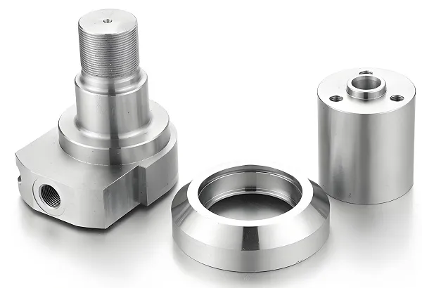
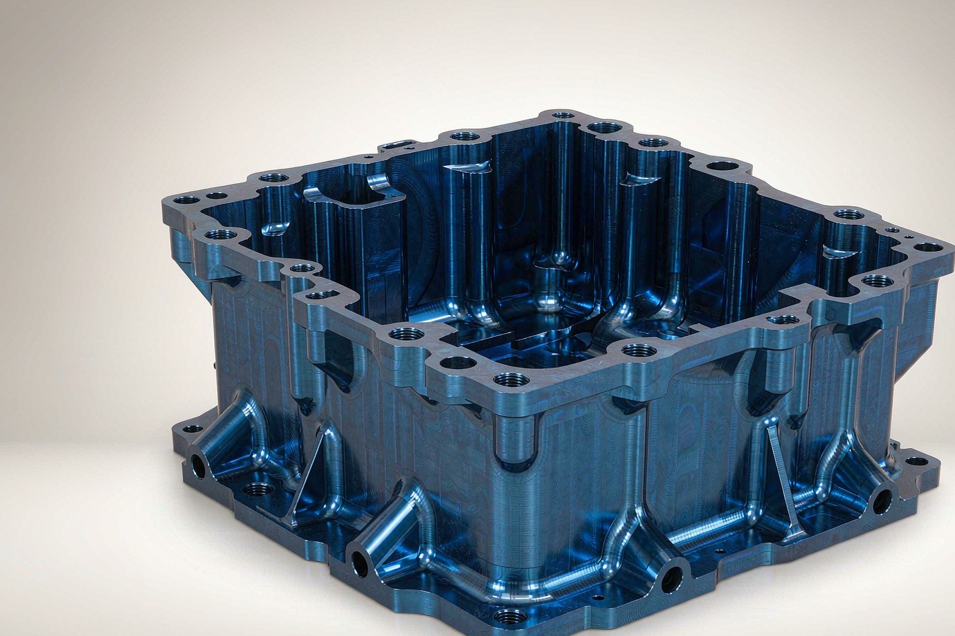
Complex 5-axis CNC machined housings are precision enclosures and bodies — gearbox cases, valve bodies, sensor enclosures, optical and instrument mounts, pump and hydraulic shells, robot actuator housings — where multiple faces carry machined features (bearing bores, seal seats, ports, mounting planes) that must stay aligned. We machine them from your drawing on 3-, 4- or 5-axis equipment, hold functional features to the tolerance the function needs (not one blanket number), verify bores, seal faces and coaxiality on a CMM, and document to your spec. They are machined from solid stock — not folded from sheet or molded — which is why they suit pressure-retaining and precision-alignment roles. Founded in 1998, we run 100+ machines across six processes under one ISO 9001:2015 quality system.
Types of Housings We Machine
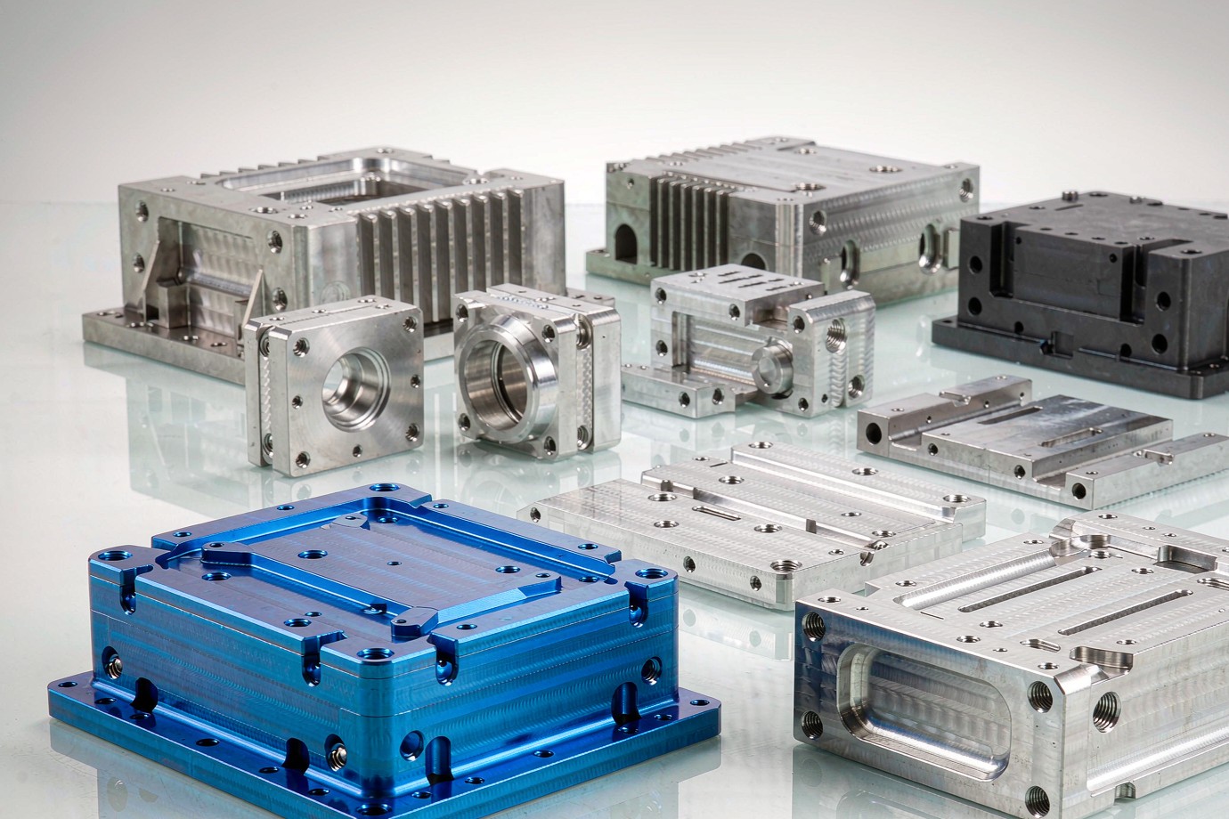
A "housing" covers a wide range of precision enclosures. The families below are the ones procurement engineers most often source as machined parts; each is built to your drawing, not to a catalog shape. They are solid-block CNC machined components — distinct from bent-sheet enclosures and injection-molded shells — which is why they are chosen where bores must stay coaxial and a face must stay flat under load or pressure.
Gearbox & Transmission Cases
Bearing bores, shafts seats and oil galleries that must stay coaxial across multiple faces.
Valve Bodies & Manifolds
Cross-drilled ports, seal seats and flat mounting faces for controlled flow and no leakage.
Sensor & Electronics Enclosures
EMI-shielded, sealed bodies with located connector and mounting features.
Optical & Instrument Mounts
Stable, low-distortion bodies where a datum plane and bore must hold an optic or shaft.
Pump & Hydraulic Shells
Cavities, port bosses and seal faces for fluid power, often with thin walls.
Robot & Actuator Housings
Joint and actuator bodies with bearing seats and cable routing, sometimes very thin-walled.
Why Complex Geometry Needs 5-Axis
Short answer: a housing is hard not because it is big, but because its features live on faces that do not share one direction. When bearing bores, seal seats, ports and mounting planes must stay aligned, every extra setup is a chance to lose that alignment.
Bores and seats on non-parallel faces reach the part from the correct angle in fewer setups.
Cutting related features from one located setup protects coaxiality and position tolerance.
Long bores, under-cuts and angled ports are reached without special long tools or re-fixturing.
Stable, symmetric setups reduce the flex that ruins flatness and bore position on thin walls.
But 5-axis is a means, not a badge. Many housings are fully handled on 3-axis with indexing, or on 3+2 positional 5-axis, and forcing simultaneous 5-axis where it is not needed only adds cost and risk. We propose the fewest setups that still hold your datums — see our CNC machining and manufacturing overview for the wider capability.
5-Axis Capability — 3+2 vs Simultaneous
Short answer: for the typical multi-face prismatic housing, 3+2 (positional) 5-axis is usually the right choice; simultaneous 5-axis is reserved for compound-curved or deeply under-cut surfaces. We select the mode from the model, not by default.
Most housings
Part tilted to a fixed angle, then milled in 3-axis mode. Rigid, easy to hold tolerance, datum-consistent — ideal for prismatic faces and bores.
Freeform surfaces
All axes move together for compound curves and deep under-cuts. Needed less often, but decisive for sculpted shells.
Simpler bodies
Where features suit one or two indexed orientations, standard 3-axis is the most economical route.
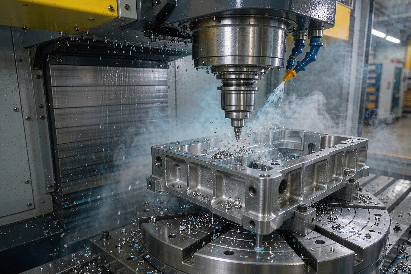
Envelope note: the maximum part size on a 5-axis machine is not the same as the largest general 3-axis envelope — the rotary/tilt table and reach set the practical bound. State your part's bounding box (L × W × H) so we confirm fixturing and machine fit rather than assuming from a category. Equipment includes 5-axis machining centers (such as DMG MORI DMU-class machines) with integrated rotary/tilt tables, alongside 3- and 4-axis mills and turning centers.
Machining Workflow
The chain a buyer should expect from drawing to documented release — each step is a control point, not a hand-off black box.
Datums, GD&T, thin walls, cavities and tolerance hierarchy reviewed before cutting.
Grade, condition and heat/lot confirmed against the material certificate.
Stock removed with heat and load controlled so the part does not distort.
CTQ bores, seal faces and contours brought to the drawing from stable setups.
CMM verifies critical and geometric features against the drawing.
Material cert, dimensional report and FAI (on request) released with the parts.
Materials for Housings
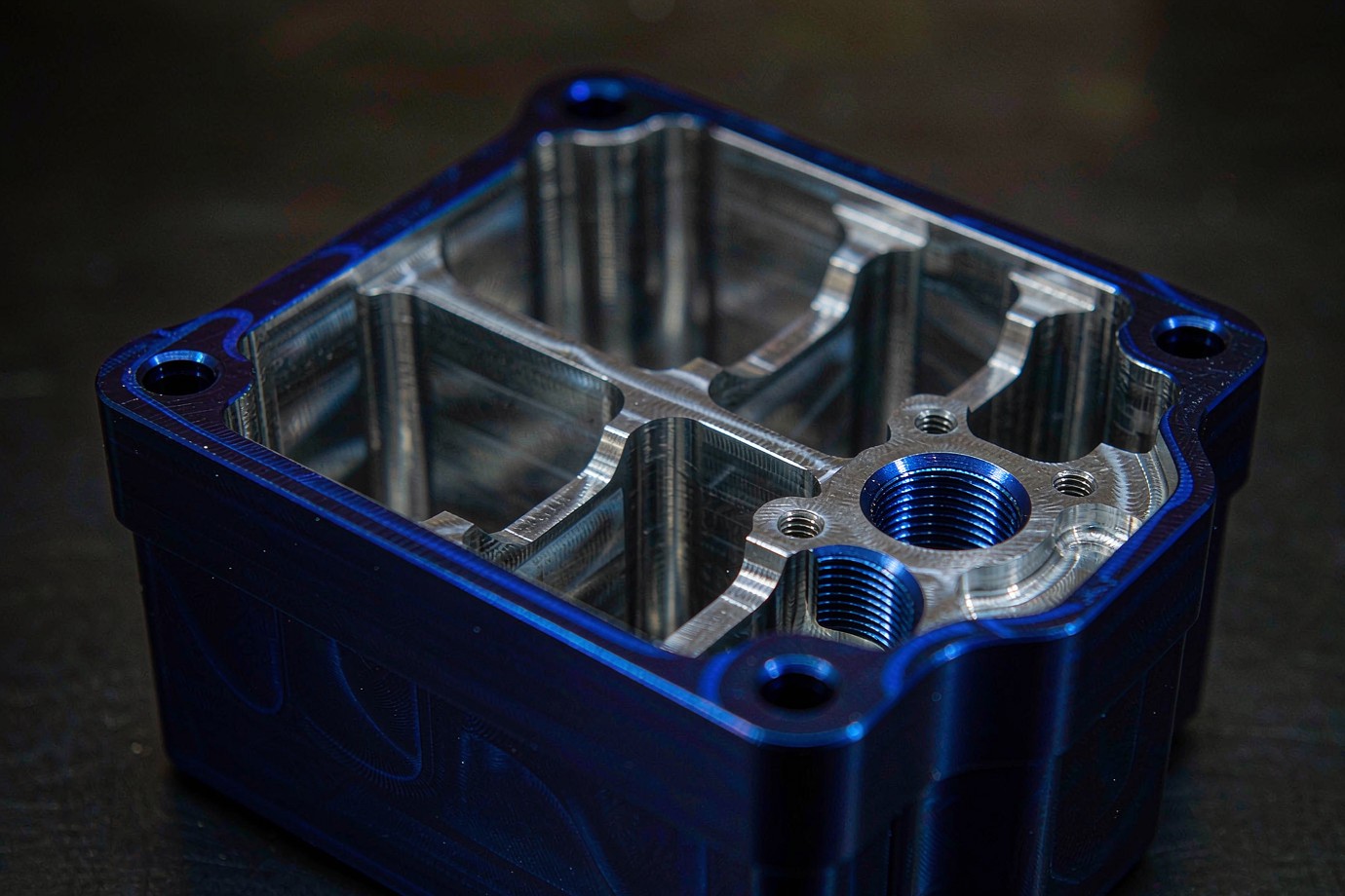
Housing material is a function of the loads, environment and weight target — it also affects how bores and seal faces behave. We confirm the exact grade and condition on the drawing before cutting.
| Material (standard / grade) | Housing use | Why a buyer chooses it |
|---|---|---|
| Aluminum 6061-T6 | General enclosures, mounts | Light, stable, easy to anodize; good first choice for most bodies. |
| Aluminum 7075-T6 | High-strength, thin-wall | Higher strength-to-weight where walls must stay thin yet rigid. |
| Stainless 304 / 316 | Corrosive, washdown, pressure | Corrosion resistance and strength for fluid and outdoor roles. |
| Titanium Ti-6Al-4V (Grade 5) | Aerospace, weight-critical | Strength-to-weight and corrosion; harder to machine, planned as such. |
| Engineering plastics (PEEK, etc.) | Insulating, light, quiet | Non-conductive or low-mass bodies where metal is wrong. |
For machined aluminum, brass and stainless parts across programs, see our CNC machined aluminum, brass & stainless parts page, and for the full material list browse the materials hub.
Technical Challenges in Housing Machining
The cost and risk of a housing live in a few recurring features. We review each in DFM rather than at first article.
Bore-to-bore coaxiality
Two bores that must share an axis across faces — protected by datum strategy and minimal setups, not by axis count alone.
Flatness & finish
A flat, low-roughness face is what a gasket or O-ring seals against; flatness is set by setup and verified by CMM.
1–2 mm walls
Sensitive to deflection and chatter; managed with short reach, symmetric setups and staged passes.
Tool access
Deep pockets need reach and chip evacuation; wider radii and longer tools are traded against finish.
Internal radii
Constrained by tool diameter; smaller radii raise cycle time and tool cost.
Dimensional stability
Material and coolant strategy keep bores and faces within band across a run.
Honest boundary: we machine the geometry to your drawing and verify it. Pressure-retaining or leak-tight behaviour is a function of the design (wall, seal, fastening) and, where required, a separately planned test — not a property we claim by default.
Tolerances & GD&T
Short answer: tolerance is not one number. It follows geometry, wall, datum strategy, fixturing, tool wear and inspection — three practical tiers:
General machining and finishing. Non-critical and cosmetic dimensions.
Controlled finishing and tighter setups. Features needing better-than-general control.
Qualified CTQ features only — bearing seats, mating bores, locating surfaces, hole position — confirmed by CMM.
Reference basis: dimensions are confirmed against your drawing together with ASME Y14.5-2018 / ISO 22081:2021 as applicable. ISO and ASME are related but not interchangeable, so the drawing states which standard applies rather than assuming one. ±0.005 mm (qualified) is realistic on selected features, not a uniform value across every dimension; express CTQ features with datums and feature control frames.
Surface Finishing
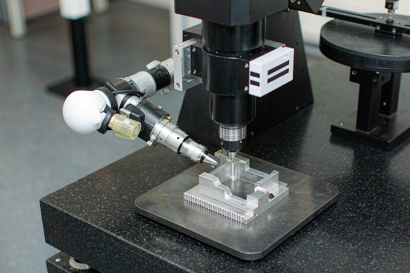
Finishing is specified per feature, not applied to the whole part blindly — an anodized seal face, for example, can lose flatness if the coating thickness is not accounted for in the drawing.
| Finish | Scope | Notes |
|---|---|---|
| As-machined | In-house | Standard mill/turn finish; Ra specified per feature. |
| Bead blast | In-house | Uniform matte texture; cosmetic and handling-related. |
| Anodizing (Type II/III, Al) | Audited external | Adds coating thickness — account for it on seal faces and bores. |
| Passivation (ASTM A967, SS) | In-house where qualified | Stainless corrosion layer. |
| Powder coat / plating | Audited external | Colour and film thickness per spec. |
Honest boundary: as-machined, bead blast and passivation (where the line is qualified) are handled in-house. Anodizing, powder coating and plating are coordinated through audited external partners, with finish certificates available on request. Final finishing scope is confirmed per project, so tell us your finish requirement when you request a quote.
Case Studies
Three representative jobs show how the workflow maps to real housings. Values are characteristic of defined projects, not standard claims.
Hydraulic Multi-Face Housing — 3+2 Positioning
- MaterialAluminum 7075-T6
- Process3+2 positional 5-axis
- Features6 faces, cross bores, seal seats
- Bore positionØ0.05 → Ø0.02 mm
- InspectionZeiss Prismo CMM
- Lead time10 working days
Machined on 3+2 so all faces were cut from one located setup, holding bore position within Ø0.02 mm where the as-received plan allowed Ø0.05 mm. Roughing controlled heat and distortion; finishing brought the seal seats and cross bores to the drawing. The first article was CMM-measured before repeat production.
Aviation Aluminum Seal-Face Housing
- MaterialAluminum 6061-T6
- Process4 + 5-axis finishing
- FeatureSeal face flatness
- Flatness0.015 mm
- InspectionCMM + surface plate
- DocumentationFAI on request
A single datum reference frame and symmetric fixturing kept the sealing face flat to 0.015 mm across the part. Flatness was verified on a surface plate and by CMM, with the result recorded against the feature control frame rather than judged by a generic number.
Robot Actuator Housing — 1.2 mm Thin Wall
- MaterialAluminum 6061-T6
- Process5-axis, thin-wall strategy
- Wall1.2 mm
- FeaturesBearing seat + cable route
- InspectionCMM bore + profile
- Lead time8 working days
Short tool reach, symmetric clamping and staged passes controlled the flex that 1.2 mm walls invite. The bearing seat and wall profile were CMM-checked so the part held shape and fit the actuator assembly after coating.
Quality & Inspection
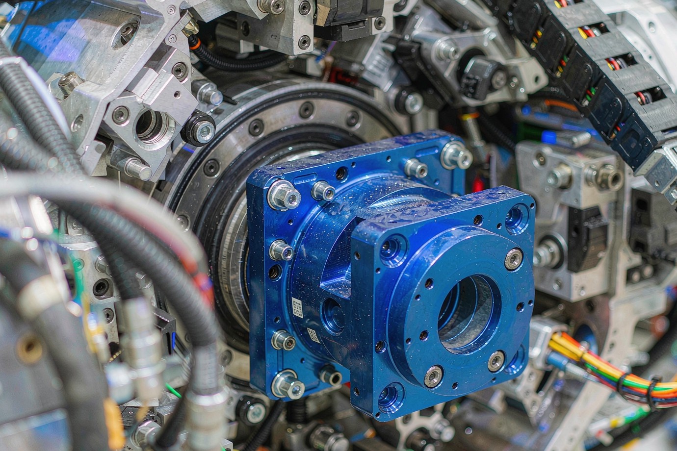
One quality system spans machining and finishing, with feature-specific checks so your receiving inspection sees one standard.
- Incoming verification — material certificates and stock check against the order.
- First-article check — key bores, seal faces and datums verified before the run.
- In-process sampling — periodic checks to catch drift early.
- CMM inspection — critical and geometric features measured on a Zeiss Prismo (±0.0005 mm capability).
- Fit & feature check — bores, position and flatness against the drawing.
- Finish verification — coating thickness and appearance confirmed.
- Final packing — clean, labelled and protected for transit.
Material mill/test certificates and inspection reports such as CMM reports or FAI reports per AS9102 (on request) can be supplied. Aerospace-related work is supported under AS9100-aligned and medical under ISO 13485-aligned controls; the quality system is ISO 9001:2015 certified.
DFM & Sourcing Notes
Most housing cost and risk are set during design. Review these before requesting a quote:
- Bounding box — give L × W × H; 5-axis travel differs from the largest general 3-axis envelope.
- Wall thickness — keep walls proportionate to size; tell us which walls are functional.
- Datum strategy — a clean datum reference frame protects coaxiality and flatness.
- Functional vs cosmetic — mark the features that must hold tolerance so we spend there.
- Tolerance hierarchy — express CTQ bores and seal faces with feature control frames.
- Seal-face finish — specify flatness and Ra; if anodizing, account for coating thickness.
For the wider manufacturing scope, see our manufacturing services overview.
Request a Quote
Tell us what you need and we return a drawing-based quote with machining, inspection and documentation spelled out. There is no form on this page — use the button to open our secure quote window and upload your CAD.
Information that speeds up your quote
Send a 3D model and/or 2D drawing. The more of the following you include, the faster and more accurate the quote.
Note: this page intentionally carries no input form. Click Upload CAD for Housing DFM Review to open our secure quote window, or email your files with the details above.
Frequently Asked Questions
What are 5-axis CNC machined housings?
When does a housing actually need 5-axis machining?
Is simultaneous 5-axis always better than 3+2 for housings?
What materials can you machine housings from?
What tolerances can a machined housing hold?
How do you hold bore-to-bore coaxiality and seal-face flatness?
Can you pressure-test or leak-test a machined housing?
What is your minimum order quantity for housings?
How fast can you deliver 5-axis machined housings?
What files do I need to send for a housing quote?
Ready to machine your 5-axis housing?
Send your CAD model and drawing. We will review the geometry and tolerances, run DFM, and define the machining, inspection and documentation plan for your housing.
Xiamen Goldcattle Plastic & Metal Products Co., Ltd. — Founded in 1998 · Customers in 100+ countries · ISO 9001:2015 certified.