Industrial Valve Body CNC Machining: Supply Scope, Standards and RFQ Guide
A valve body is not a bracket with holes in it. It carries flow passages, sealing interfaces and port geometry that determine whether an assembled valve works. This page is written for buyers who already hold a drawing and need to settle four questions before placing an order: what exactly is being supplied, who owns conformity to valve standards, which features can actually be inspected, and what an RFQ must contain to produce a usable quotation.
At a Glance
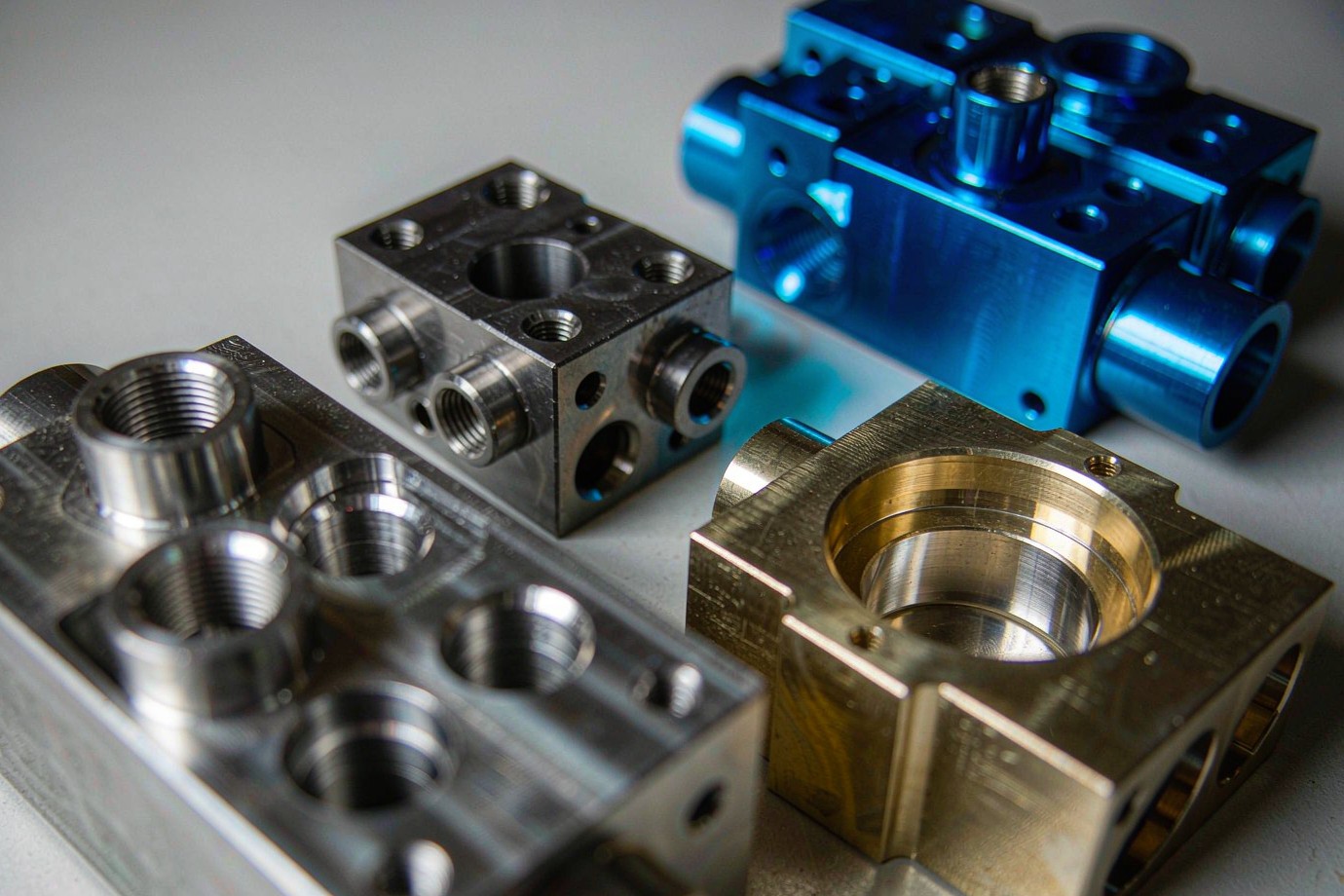
Industrial valve body CNC machining is the manufacture of valve housings and fluid-control components to an approved engineering drawing, producing specified ports, internal passages, bores, sealing interfaces and mounting features. Depending on the design, operations may include milling, turning, drilling, boring, threading and finishing. Critical dimensions, sealing requirements and inspection scope come from the drawing and the applicable valve product specification, not from a general machine capability list. Xiamen Goldcattle Plastic & Metal Products Co., Ltd. is a direct manufacturer of drawing-based machined components. We are not a certified valve manufacturer, we do not operate a supplier marketplace, and we do not publish automated instantaneous pricing. A dimensionally conforming machined body is a component; it is not, by itself, a completed pressure-qualified valve. This page exists to make those boundaries explicit before you send a drawing, because most valve-body sourcing disputes start with an undefined supply scope rather than with a machining error.
1. What Is Supplied — and What Is Not
Component supply scope is the written statement of what leaves the machine shop: the machined body alone, or the body plus a specified treatment, or the body plus agreed inspection documents. It also states what is excluded. Fixing this before quotation prevents a machined component from being silently treated as an assembled, tested and conformity-assessed valve.
Buyers rarely ask this question first, yet it determines the price, the inspection plan and the acceptance criteria. A request that says only we need a valve body can mean four different orders. We therefore ask you to choose one of the following scopes, or to define your own in writing.
| Activity | Status in our declared scope | Why it is classified this way |
|---|---|---|
| Reading the drawing, datum scheme and passage map | In scope, before quotation | Process route and inspection feasibility cannot be judged from an external photograph. |
| CNC milling, turning, drilling, boring, threading and deburring | In scope, to the drawing | These are the core machining operations for a valve body component. |
| Surface treatment, special cleaning and protective packing | Agreed at RFQ | Requirements differ by order and can change a finished sealing dimension. |
| Dimensional report, first article documentation, material certificate | Agreed at RFQ | Your receiving quality system defines which records are actually required. |
| Valve design, pressure boundary calculation and material selection for duty | Outside our declared scope | These belong to the valve or equipment designer who owns the product specification. |
| Complete valve assembly, trim, actuation and final functional testing | Outside our declared scope | We supply machined components, not finished valves. |
| Product conformity assessment and certified product marking | Outside our declared scope | Conformity of a completed valve or assembly is established by its responsible manufacturer. |
Why we state this so plainly: a machine shop that accepts a valve body drawing is not thereby a valve manufacturer. If your purchase order requires an assembled and tested valve, or a licensed product mark, raise it before quotation so the responsible party and the required evidence are identified rather than assumed.
2. Valve Standards and Conformity Responsibility
Valve bodies sit closer to regulated pressure equipment than most machined parts. A professional buyer will ask which product standards apply and who is accountable for demonstrating compliance. Our position is deliberately narrow: we machine to the drawing and to the machining requirements a customer identifies from the applicable valve standard, and we document what we measured. We do not present that documentation as conformity of a completed valve.
| Standard or regulation | What it governs | How it affects a machining RFQ |
|---|---|---|
| ASME B16.34 | Pressure-temperature ratings, dimensions, materials, examination, testing and marking for flanged, threaded and welding-end valves | The responsible valve manufacturer identifies which requirements flow down to the machined body. We review those requirements against the drawing when they are supplied to us. |
| ISO 5208 | Pressure testing of metallic industrial valves, including pressure boundary integrity and closure sealing performance | Separate from dimensional inspection. A dimensional report on a machined component is not an ISO 5208 valve pressure test report. |
| API Spec 6D | Design, manufacture, material, quality, assembly, testing and marking for pipeline valves | Only relevant where the buyer identifies a pipeline valve project. Product marking under an API Monogram licence is not a machining-shop entitlement. |
| EU PED 2014/68/EU | Design, manufacture and conformity assessment of pressure equipment above its applicability threshold | Applicable regulatory and conformity assessment requirements are defined by the responsible equipment or valve manufacturer. |
Conformity boundary. For pressure equipment projects, applicable regulatory and conformity assessment requirements should be defined by the responsible equipment or valve manufacturer. Component machining documentation does not independently establish conformity of the completed valve or assembly.
Accordingly, we make no claim of product-level valve certification, licensed product marking, or conformity assessment of a completed assembly. Where a customer specification calls for examination, pressure or leak testing, or a specific certificate package, the test object, acceptance criteria, responsible party and the party issuing the record are written into the RFQ response. Testing of this kind is evaluated per project and is not offered as a uniform in-house service. We also do not claim that a CMM measurement of external features proves every hidden internal passage is within specification; the verification coverage is a separate question, dealt with below.
3. Who This Page Is For
This page is written for engineers and buyers who already own a valve body definition and need an external machining partner. It is not a product catalog, and it is not a general introduction to how valves work. If you recognise your situation in the table below, the RFQ and acceptance sections will be more useful than a capability brochure.
| Buyer type | What they usually need | What they most often need clarified first |
|---|---|---|
| Industrial valve manufacturers | Repeat batches of machined bodies, bonnets and flow-control housings to a controlled revision | Which characteristics are critical to quality, and which documents must accompany each batch |
| Hydraulic and pneumatic equipment OEMs | Manifold blocks, cartridge valve blocks and subplates with intersecting passages | The passage connection map, intersection breakout and internal burr acceptance method |
| Fluid control and instrumentation OEMs | Compact precision bodies with fine bores, taper metering surfaces and small ports | Bore finish, concentricity to the datum scheme and protection of sealing faces |
| Pump and process equipment manufacturers | Flow-control housings and connection blocks in stainless or carbon steel | Material certificate requirements, surface treatment and corrosion-related drawing notes |
| Replacement and retrofit buyers | A small number of bodies reproduced from an existing part and a drawing to be confirmed | Whether a controlled drawing exists, and who owns the reverse-engineered specification |
This page will be less useful if you are looking for an off-the-shelf finished valve, a complete valve assembly, a licensed pressure-valve product, or a supplier marketplace that aggregates many factories. We are a single direct manufacturer working to customer drawings, and our quotation is an engineer-reviewed response rather than an automated price. For a broader view of our machining capability, see CNC machining services; the submission route is described on the instant CNC quote page.
4. The Eight Feature Groups Your Drawing Must Define
The diagram below is a feature map, not a design. It names the eight groups that most often decide whether a valve body quotation is complete and whether the delivered part can be accepted. Use it as a checklist against your own drawing package before an RFQ goes out.

| Feature group | What the drawing should state | Typical acceptance question |
|---|---|---|
| Threaded fluid ports | Thread system, size, depth, direction, port face and sealing form | Is the gauge method defined, and does the connector seal on the thread, a cone, a spotface or an O-ring? |
| Internal flow passages | Which bores connect, which must remain isolated, and the section views that prove it | Can the connection and isolation be confirmed from the supplied model and section views? |
| Cross-drilled holes and plugs | Drill entry positions, blind depths, plug type and breakout expectations | How is intersection breakout treated, and where is burr removal required? |
| Valve bore and spool cavity | Diameter, roundness, cylindricity, position, surface finish and mating clearance | Which fit governs, and with which instrument will it be measured? |
| Seat and sealing surfaces | Seat angle, contact face, flatness, roughness and concentricity to the bore | Are these faces protected through deburring, coating and packing? |
| O-ring grooves | Width, depth, corner radii, position and surface finish | Does the specified coating change the finished groove dimension? |
| Mounting and actuator interfaces | Bolt pattern, flatness, perpendicularity, boss heights and datum relationships | Are the related faces machined under one datum relationship? |
| Datum reference scheme | Which features establish the datums and how geometric tolerances are applied | Is the drawing standard declared, so the tolerance callouts are unambiguous? |
Reading the table: the middle column is what we need in order to quote; the right-hand column is what your receiving inspection will ask. A drawing that specifies a bore diameter but no datum scheme, or a thread but no sealing face, produces a quote built on assumptions.
5. Internal Passages, Burrs and Verification Coverage
Cross-drilled passages are where valve body machining differs most from ordinary prismatic work. Two holes that should meet must meet; two channels that should stay isolated must stay isolated; and the breakout where they intersect must not leave a loose burr in a fluid path. Those conditions are set by the geometry, not by the machine's axis count. A passage map and section views are therefore part of the drawing package, not optional extras.
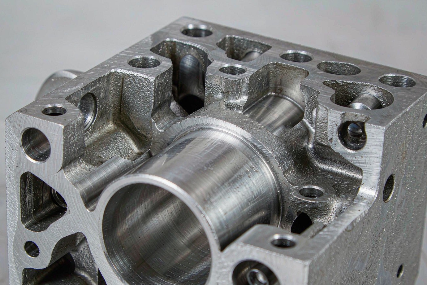
| Region or condition | Verification category | What has to be agreed at RFQ |
|---|---|---|
| External faces, port positions, bolt patterns, accessible bores | Directly verifiable with conventional dimensional inspection | Which characteristics appear in the report and to what drawing revision |
| Sealing faces, seat geometry, O-ring grooves, thread form | Directly verifiable with an agreed method and instrument | Flatness, roughness and gauge method, including any surface treatment effect |
| Open internal passage entries and shallow blind holes | Conditionally verifiable | Whether visual, borescope or another examination method is required and recorded |
| Hidden cross-hole intersections deep inside a manifold | Not proven by external inspection alone | Deburring method, cleaning step, acceptance criterion and, where needed, a buyer-defined or third-party examination |
| Residual chips or contamination after machining | Requires a defined cleanliness requirement | Cleaning method, flushing or particle criterion if one applies, and protective packing |
| Leak tightness between isolated channels | Functional test, not a dimensional check | Who performs the test, on which assembly, against which acceptance criterion |
We describe deburring and cleaning in terms of the agreed method and the regions it reaches. We do not claim that every hidden internal passage is burr-free on the basis of an external visual check, and we do not substitute a CMM report for a functional test. If a project needs thermal deburring, abrasive-flow machining, boroscope records, a specified particle count or an external laboratory, that is identified during review so the responsibility and the cost are visible before an order is placed. Inspection documents, testing and file-retention practice are confirmed per project.
6. Port Threads and the Difference Between a Thread and a Seal
A frequent RFQ shortcut is to list a thread callout and assume the sealing arrangement is therefore defined. It is not. A tapered pipe thread, a parallel pipe thread with a bonded seal, an O-ring boss port and a metric port with a spotface each place the seal in a different location. The mating connector, the port face and the groove geometry all form part of the interface. Machining the thread correctly is necessary, but it is not sufficient.
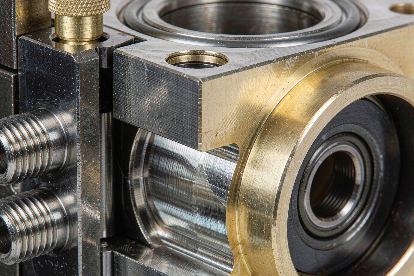
| Port specification | Where the seal is normally made | What the drawing should additionally define |
|---|---|---|
| NPT | On the tapered thread with a sealant | Thread depth, engagement, port face and permitted sealant |
| NPTF | On the dry-seal tapered thread | Gauge requirement and the condition of the mating thread |
| BSPP | On a gasket, bonded washer or shoulder face, not on the parallel thread | Spotface diameter, face flatness and sealing washer detail |
| BSPT | On the tapered thread | Thread form, engagement and direction relative to other ports |
| Metric threads | On a defined face, washer or O-ring | Pitch, depth, counterbore and the sealing element |
| SAE J1926 / O-ring boss | On an O-ring compressed in a machined spotface | Spotface geometry, groove or chamfer detail and surface finish |
| ISO 6149 | On an O-ring in a defined metric port cavity | Port cavity form and the surface finish of the sealing area |
These specifications are listed as the interfaces a buyer may nominate, not as a claim that every form is in routine production. Thread gauging method and gauge availability are confirmed per project before we commit to a particular form. Port alignment, thread runout and the condition of the sealing face after coating are included in the review, because a damaged O-ring land is a leak path that no thread gauge will detect.
7. Dimensional Accuracy and the Tolerance Basis
Valve bodies concentrate risk in a handful of related features rather than across the whole part. The bore-to-seat relationship, the port-to-passage position and the flatness of a sealing face usually matter more than the general outline. We therefore ask for the critical-to-quality chain on the drawing, and we do not apply one blanket value across the whole part. There is no blanket part-wide value and no blanket ISO 2768-mK default on this page.
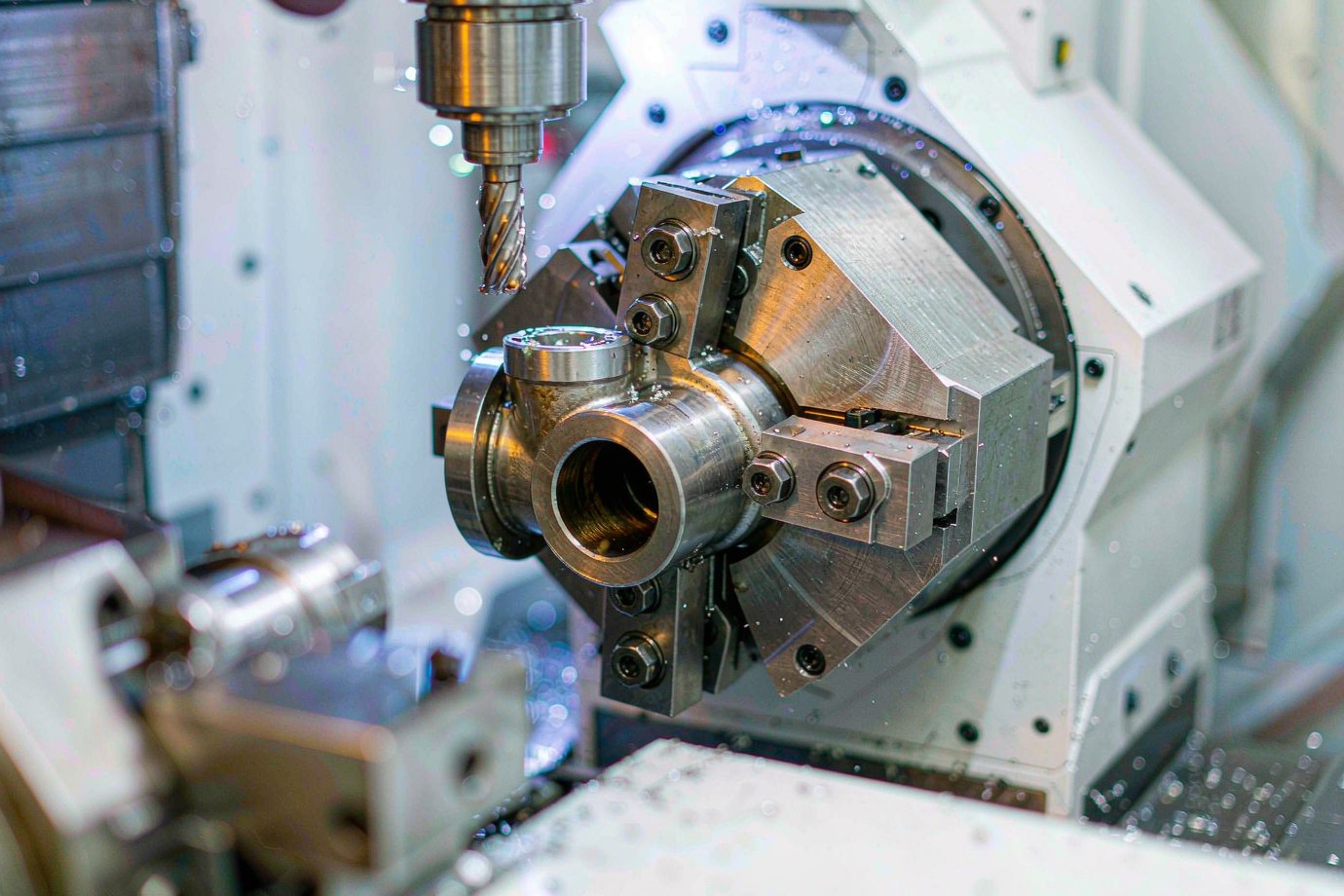
| Critical chain | Characteristics normally controlled | Why the relationship matters |
|---|---|---|
| Seat to bore | Concentricity, seat angle, bore roundness and surface finish | Determines whether the closure element seats consistently |
| Bore to port | True position, perpendicularity and port alignment | Controls the flow path and the intersection with the cavity |
| Sealing face to datum | Flatness, roughness and distance to the datum scheme | Controls gasket or O-ring compression in the assembly |
| Mounting pattern to body | Hole position, boss height and perpendicularity | Controls fit to the actuator or subplate without distortion |
| Thread to port face | Depth, runout and spotface relationship | Controls connector engagement and sealing land contact |
The drawing standard is the authority. We work to ASME Y14.5-2018 (R2024) or to ISO GPS / ISO 22081:2021 as declared on the customer drawing, and these frameworks are not interchangeable; mixing their callouts on one interface creates exactly the ambiguity that leads to rejected parts. Tight values are evaluated per feature and only on qualified features, never uniformly across the whole part, and ±0.005 mm where discussed is a qualified-feature target rather than a part-wide promise. Achievable tolerances, surface finishes and wall sections depend on geometry, material, blank condition, workholding, machining strategy and the inspection method, so any process figures quoted during review are initial engineering references confirmed per project, not fixed values.
Setup strategy follows the geometry. Fixed-angle ports and multi-face prismatic bodies are often best cut in 3+2 indexed mode, where the rotary axes are locked during cutting; Simultaneous 5-axis is not assumed as the default route and is only warranted when the tool vector must change continuously along a surface. Related features are held in one datum relationship where the geometry permits, which reduces the stack of re-clamping errors. Our capability overview for multi-axis equipment sits on the 5-axis CNC machining services page, and rotational work is covered under CNC turning services.
8. Inspection Documents and Material Traceability
Document scope is a commercial decision as much as a technical one. A prototype may need only an agreed dimensional check; a repeat production order for a regulated assembly may need first article documentation, certificate packages and batch records. The mistake to avoid is assuming a factory's general capability equals the documents issued for your particular order.
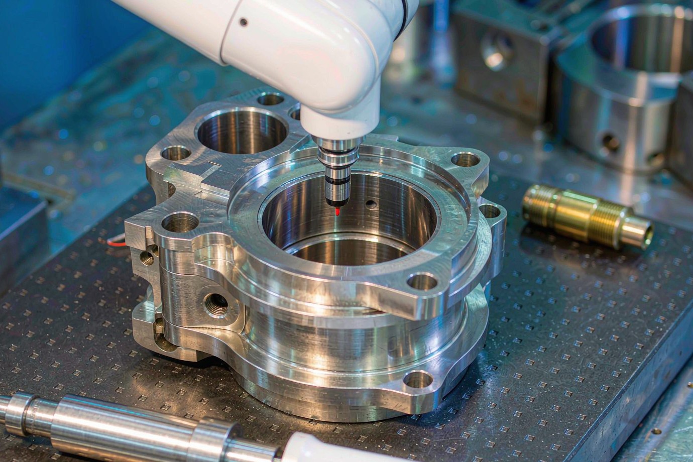
| Document or record | Default status | What decides whether it is supplied |
|---|---|---|
| Dimensional inspection report for agreed characteristics | Agreed at RFQ | The characteristics and report format named in the purchase order |
| CMM measurement of external and accessible features | Agreed at RFQ | Which features are measurable and which method is accepted by receiving inspection |
| Thread and bore verification records | Agreed at RFQ | The gauge method and the thread forms on the drawing |
| First article inspection documentation | Agreed at RFQ | Whether a first article is required before a repeat batch is released |
| FAI reports per AS9102 on request | On request | Stated explicitly in the order; this is a reporting standard, not a certification |
| EN 10204 3.1 material certificate | Agreed at RFQ | Whether the mill supplies the certificate for the ordered material and condition |
| Batch and revision traceability records | Agreed at RFQ | Your internal traceability requirement for repeat orders |
| Pressure or leak test record for a completed valve | Outside the default scope | A separately documented test object, responsible party and acceptance criterion |
ISO 9001:2015 is certified. AS9100-aligned process controls, ISO 13485-aligned process controls, ISO 14001-aligned environmental practices and FAI reports per AS9102 on request describe process alignment and documentation; they are not additional certifications, and we make no claim of blanket third-party product certification. Our certification overview is on the quality certifications page. NDA terms, file-retention practice and the handling of controlled customer data are confirmed per project.
9. What to Send for a Valve Body Quote
The fastest way to a usable quotation is a package that lets an engineer decide the process route and the inspection scope without a second round of questions. The table below is a preparation checklist for your own team; this page carries no input form. Use the button to open our quote window when the package is ready.
| Documentation category | What to provide | Why it changes the quotation |
|---|---|---|
| 2D drawing | Complete dimensioned drawing with revision number | Defines the acceptance criteria and the drawing standard |
| 3D CAD | STEP, IGES or an agreed native format at the same revision | Allows the passage geometry and tool access to be checked |
| Section views | Cuts through internal flow passages and cross holes | Shows connection and isolation that an external view hides |
| Passage map | Which bores connect and which must stay isolated | Prevents an undetected leak path between channels |
| Material | Exact grade, condition and any standard it must meet | Determines tooling, cutting parameters and certificate availability |
| Blank condition | Bar stock, block, casting or forging, and who supplies it | Determines stock allowance, distortion risk and machining time |
| Port specification | Thread system, size, depth, direction and sealing form | Determines tooling, gauging and port-face machining |
| Valve bore | Diameter, fit, finish and roundness or cylindricity requirement | Determines whether boring, reaming, grinding or honing is needed |
| Sealing details | Sealing face flatness, roughness and O-ring groove parameters | Determines machining order and handling protection |
| Duty information | Intended pressure and temperature range and design conditions approved by the buyer | Context for the designer's material and wall decisions; not a machining claim |
| Surface finish | Specified roughness, treatment and any cosmetic faces | Changes the finished dimension of functional features |
| Inspection | Required dimensional report, certificates and first article format | Determines the measurement plan and documentation cost |
| Testing | Whether pressure, leakage or other testing is required, and by whom | Defines responsibility rather than leaving it implied |
| Quantity | Prototype quantity plus expected repeat batch pattern | Determines fixture planning, revision control and unit economics |
This is a preparation checklist and carries no input form. Click Submit Your Valve Body Drawing to open our quote window. We make no free-shipping promise and no guarantee of a specific price or delivery date before review.
Have a valve body drawing ready for review?
Send the drawing set, the passage map and the component supply scope you need. You will get an engineering review of the geometry, the critical interfaces, the verification coverage and the documentation scope before a quotation is issued.
10. How to Evaluate a Valve Body Machining Supplier
Procurement teams reduce risk by converting vague promises into verifiable answers. The questions below are deliberately operational: a capable supplier should be able to answer in terms of drawings, methods and documents, while an unreliable one will answer in adjectives. Use them as a comparison grid when two quotations look similar in price but differ in scope.
| Ask this | A useful answer sounds like | Warning sign |
|---|---|---|
| Which features do you treat as critical to quality? | Named bore, seat, sealing face and port relationships referenced to a datum scheme | A single blanket tolerance applied to the entire part |
| How will you verify hidden cross-hole intersections? | A stated method, its coverage limits and what still needs buyer or third-party confirmation | A blanket claim that every internal passage is burr-free based on visual inspection |
| Which thread forms and gauges apply to this order? | The specific form, gauge method and confirmation that availability is checked | All common threads listed as routine capability without checking the drawing |
| Which documents come with the shipment? | A list tied to the purchase order, with the issuing party and revision | General factory certificates offered as proof for an unnamed specific order |
| Who owns pressure and leak testing? | A clear division between component inspection and product-level testing | Dimensional reports described as equivalent to valve pressure tests |
| How are drawing revisions controlled? | A named revision on the quotation and on the production router | Verbal changes accepted without an updated drawing |
| What is the supply scope in writing? | Machined body, treatment and documents stated separately | An assumption that a machined body includes assembly and certification |
| What happens between prototype and repeat batches? | First article approval, fixture planning and batch traceability | Only a minimum order quantity with no approval gate |
None of these questions requires a supplier to claim the largest machine or the lowest price. They test whether the supplier can describe a controlled process and its limits. That is usually a better predictor of a smooth first article than a capability list, and it is why we publish the boundaries on this page rather than a set of superlatives.
11. From Prototype to Repeat Purchase
A valve body order is rarely a single transaction. The commercial value lies in approving a first article and then reproducing it with controlled revisions. The stages below describe the buyer's decision points, not a marketing funnel.
| Stage | Output you should receive | Your decision |
|---|---|---|
| RFQ and engineering review | Questions on passage map, critical features, scope and inspection method | Confirm the drawing revision and the component supply scope |
| Quotation | A defined machining, treatment and documentation scope tied to that revision | Approve the scope, not just the unit figure |
| Prototype machining | One piece or a small batch produced under the agreed datum and inspection plan | Assess fit, interfaces and the agreed report |
| First article approval | First article inspection documentation where the order requires it | Release or request a documented change |
| Production planning | Fixture approach, setup sequence and revision control for repeat runs | Confirm the expected batch pattern and call-off rhythm |
| Repeat batches | Parts to the approved revision with the agreed records and traceability | Manage engineering changes as new revisions, not as shop-floor notes |
The minimum order quantity is 1 piece, which allows a prototype to be evaluated before a production commitment. Published sampling, low-volume and production windows are initial engineering references confirmed per project, not fixed values; they depend on material availability, blank form, the number of setups, any external treatment and the inspection documents in scope. We do not offer a blanket delivery promise. For material behaviour on specific grades, see the materials hub, and for stainless work see stainless steel CNC machining. Where a drawing carries tight geometric callouts, the tight-tolerance CNC machining page explains how we treat qualified features.
12. Frequently Asked Questions
What is industrial valve body CNC machining?
Can you manufacture custom valve bodies from our drawings?
What types of valve bodies and fluid control components do you machine?
Which materials can be used for CNC machined valve bodies?
Can you machine intersecting internal flow passages?
Can you machine NPT, BSPP and SAE port threads?
How are sealing faces and O-ring grooves controlled?
How do you inspect internal passages and control burrs?
Do you provide EN 10204 3.1 material certificates and dimensional reports?
Do you provide pressure and leak testing, and who is responsible for valve conformity?
Need a defined scope before you release the drawing?
Send the 2D drawing, the 3D model, the passage map and the documents your receiving inspection requires. We will reply with the machining scope, the verification coverage and the conformity boundaries written into the quotation, from one prototype through to controlled repeat batches.
Xiamen Goldcattle Plastic & Metal Products Co., Ltd. — Founded in 1998 · Customers in 100+ countries · ISO 9001:2015 certified.