Mould engineering service
Custom Semi-Hot Runner Injection Molds for Your Production Requirements
A semi-hot runner is a compromise between two familiar systems, and the compromise only pays when the part, the resin and the volume all agree with it. This page sets out the hybrid architectures that exist, which one this service is built around, what has to be settled before a mould is cut, and what is measured before it ships — without quoting a saving that has not been measured on your project.
Scope of This Page
Short answer: this is the service page, and it is deliberately narrower than the topic. It covers what a hybrid runner mould is, how the decision is made for a specific part, and what is delivered with the tool. It does not repeat the general three-way cost comparison or the break-even calculation, because those belong on a separate guide and are linked rather than restated.
The split matters for a buyer. A service page answers “can you build this, and what will it involve”. A comparison guide answers “which runner type should I choose”. Mixing them produces a page that is long, vague and hard to act on, and in practice it produces two pages competing for the same search terms with the same content. The comparison, the financial model and the break-even calculator are on hot runner vs cold runner. Everything about the hybrid architecture, the engineering inputs, the trial record and the handover is here.
This page publishes no saving percentage. Claims that a hybrid runner cuts runner waste by a fixed proportion, or costs a fixed proportion less than a full hot runner, are not used here. Both quantities are outputs of a specific part, resin, cavity layout and volume. Where a number is needed, it is measured on your project and written into the trial record.
At a Glance
What “Semi-Hot Runner” Actually Means
Short answer: the name describes a family, not a design. It only means that some of the flow path is held hot and some of it is not, and different toolmakers draw the boundary in different places. A page that names the category without showing where the boundary sits has told a buyer nothing they can check.
The term is used loosely in the trade, alongside hybrid hot/cold runner and hot-to-cold runner. Two moulds can both be called semi-hot and behave completely differently: one may heat only the sprue bushing, another may heat the sprue and the main runner but leave every sub-runner cold, and a third may heat individual drops while leaving a cold section between them. The consequences differ in tooling cost, in how much material solidifies each cycle, in how many heated zones need controlling, and in what the operator has to maintain.
So the useful question is not “is it semi-hot” but “which section is heated, which section freezes, and where does the freeze happen relative to the gate”. Those three answers determine everything downstream, including the runner weight, the ejection arrangement and the maintenance list.
Four Hybrid Architectures, and Which One This Service Is Built Around
Short answer: the configuration here is a heated main runner with unheated sub-runners. That is the arrangement to check first when you compare this quotation with another “semi-hot” quotation, because a different boundary produces a different runner weight and a different tooling cost.
Variant A
Heated sprue only
The sprue bushing is heated; the entire runner from the sprue to the gates is cold and ejects with the shot.
- Lowest heated content
- Fewest controllers, simplest maintenance
- Trade-off
- Runner weight is close to a cold runner, so the material saving is small
Variant B — used here
Heated main runner, cold sub-runners
The sprue and main runner stay molten; the sub-runners that branch to each cavity are unheated and freeze.
- Removes
- The long central sprue, which is usually the largest single piece of solidified material
- Keeps
- A short frozen stub per drop, ejected with the shot
- Needs
- Correct thermal separation between the heated runner and the cold plates around it
Variant C
Heated drops, cold bridge
Each drop is heated near the gate, with an unheated section upstream between the drops.
- Closest to full hot
- Least solidified material at the gate
- Trade-off
- Most heated components per cavity, so the highest tooling and control cost of the four
Variant D
Heated manifold, cold drops
A heated manifold distributes to short unheated drops that freeze at the gate.
- Balanced filling
- Manifold temperature can be controlled independently of the drops
- Trade-off
- Manifold and plate thermal design is the critical path; poor separation shows up as unstable drops
Variant B is the configuration this service is set up for, and it is what the section drawing below illustrates. If your project needs a different boundary — for example heated drops on a large multi-cavity tool — that is a different quotation, and the difference should be visible in the price rather than hidden inside the same label.
Reading a Section Drawing: Where the Heat Stops
Short answer: five things have to be legible on the drawing before a quotation can be compared: the heated length, the freezing length, the gate position, the ejection path of the frozen runner, and the thermal separation between hot and cold plates.
Heated section — held at melt temperature Unheated section — freezes and ejects Cavity Thermocouple
Schematic, not a production drawing. The heated length, the freeze point relative to the gate and the thermal separation are the three features to check against any quotation described as semi-hot.
Where the Hybrid Sits, and What It Is Not
Short answer: a hybrid runner is not a general upgrade to a cold runner. It buys a reduction in solidified material with additional heated hardware, and it is worth considering when the solidified runner is large enough and the shot count high enough that the material recovered outweighs the hardware and its upkeep.
| Condition | What it implies for a hybrid |
|---|---|
| The sprue and main runner are a large share of the shot weight | Favourable. This is exactly the material that Variant B removes, so the return is highest where the central runner is heavy relative to the part. |
| The runner is already thin and short | Unfavourable. Little material is recovered, while heated hardware and its control are still added. |
| Shot count over tool life is low | Unfavourable. The extra tooling is spread over few cycles, so the payback may never arrive. |
| Frequent colour or material changes | Needs specific evaluation. A heated section holds the previous colour and takes longer to purge than an unheated one. |
| Resin with a narrow thermal window | Needs specific evaluation. Residence time in the heated section becomes a quality limit, not just an efficiency question. |
| Cosmetic part with a gate mark that cannot be moved | Gate position often constrains where the freeze point can sit, which can remove the benefit entirely. |
| Abrasive filled grade | Wear moves to the heated components and the narrow sections. Maintenance cost becomes part of the comparison. |
The full three-way comparison of cold, hybrid and full hot systems, including the arithmetic of payback and an interactive break-even estimator, is on hot runner vs cold runner. It is not repeated here, so that the two pages do not compete for the same query with the same table.
What Actually Decides the Choice
Short answer: six inputs, and four of them are numbers you already hold. The decision is arithmetic once those inputs exist, which is why a quotation without them is a guess with a price attached.
01
Runner weight per shot
Not part weight. What matters is how many grams solidify per cycle in the candidate layout, measured or calculated from the section drawing. This is the single number that drives the whole comparison.
02
Shots over the tool's life
Annual volume multiplied by expected years, or the total order quantity if the tool is built for one programme. A tool planned for a short programme rarely justifies added hardware.
03
Resin price and regrind policy
Recovered runner is only worth the resin price if it can be reused. The permitted regrind ratio and whether regrind is allowed on the part decide how much of the saving is real.
04
Resin thermal window
How long the grade can sit at the heated-section temperature without degrading sets a hard limit on runner volume and on machine stop time. Grades with narrow windows can rule the design out.
05
Machine and mould space
Shot capacity, clamp force, tie-bar spacing and nozzle interface decide whether the heated section even fits. A design that will not run in your press is not a saving.
06
Maintenance access and skill
Heated elements, thermocouples and controllers are wearing parts. Who replaces them, how quickly, and whether spares are held locally belongs in the comparison, not in the after-sales conversation.
Two of these inputs are frequently missing at quotation stage: the shot count over tool life, and the regrind policy. Without them the comparison can still be built, but it becomes a sensitivity analysis rather than a decision — which is what we will say if we are asked to price a runner choice without them.
Resin Compatibility, and Why There Is No List
Short answer: polyolefins, styrenics, ABS, polycarbonate and nylons are routinely evaluated for hybrid runners, but no material family is approved as a class. Suitability is a property of the grade, the section temperature and the residence time, not of the family name.
| Factor | Why it changes the design | What has to be confirmed |
|---|---|---|
| Thermal stability at section temperature | Material sitting in the heated runner between shots is exposed far longer than material passing through a cold sprue | The grade's residence-time limit at the intended temperature, from the supplier's data |
| Processing window width | A narrow window leaves little tolerance between freeze in the sub-runner and degradation in the main runner | The gap between the grade's freeze point and its degradation point, and how much of it the design uses |
| Fillers and reinforcement | Glass and mineral fillers abrade narrow sections, gates and heated components | Wear allowance at the gate and the heated section, and the expected service interval |
| Colour and material changes | The heated section must be purged, and purge loss is a real cost per changeover | How often the colour changes, and whether a second heated section is cheaper than repeated purging |
| Hygroscopic grades | Moisture in the melt affects appearance and strength regardless of runner type, and is often misdiagnosed as a runner problem | Drying specification and machine-side verification before the runner design is blamed |
| Flame-retardant and filled grades | Additives can be sensitive to extended time at temperature | Whether the grade permits the residence time the design implies, checked with the resin supplier |
This is why the page does not publish a list of “suitable materials”. A list invites a buyer to conclude that any ABS is fine, when the difference between two ABS grades in thermal stability is often larger than the difference between ABS and another family. Material data by family is on engineering materials; the grade-specific judgement is made on your project.
Mould Design: What We Need, and What It Changes
Short answer: eight inputs, and the machine data is the one most often left out. Without the intended press, the runner and cavity layout cannot be checked against shot capacity and clamp force, and the design is being drawn against an assumption.
| What you send | What it settles |
|---|---|
| 3D model (STEP or Parasolid) | Geometry, wall section, draft, and the space available for the runner and ejection |
| Fully dimensioned 2D drawing | Critical dimensions, geometric tolerances, and which surfaces are cosmetic |
| Resin grade and colour | Thermal window, fill behaviour, wear allowance and purge strategy |
| Annual and lifetime quantity | Cavity count, and whether added tooling can pay back within the programme |
| Intended injection machine | Shot capacity, clamp force, tie-bar spacing, nozzle interface and controller capacity |
| Gate type and permitted gate position | Where the freeze point sits, which decides whether the hybrid benefit survives at all |
| Target cycle and mould life | Cooling layout, plate thickness, steel selection and the maintenance interval |
| Existing mould drawings, for a conversion | Which plates, pockets and components can be retained and which have to be remade |
Four design decisions follow from those inputs and are worth stating plainly, because they are where hybrid tools fail:
- Thermal separation. The heated runner has to be isolated from the cold plates around it. Insufficient separation shows up as unstable sub-runners, slow start-up or a runner that freezes in the wrong place — and it is a plate-design problem, not a controller setting.
- Runner sizing. The heated section has to be large enough that pressure drop is acceptable and small enough that residence time stays inside the grade's window. Those two constraints pull in opposite directions, and the window is what limits the design.
- Freeze point relative to the gate. Where the sub-runner freezes determines how much material ejects, how the part is degated, and whether the gate mark is where you can accept it. Moving the freeze point closer to the cavity recovers more material but exposes the gate area to more thermal cycling.
- Ejection of the frozen runner. The stub has to leave the tool reliably every cycle. A runner that occasionally stays behind stops the press, and the fix usually costs plate work.
Flow analysis is used to check fill balance and pressure where the geometry or cavity count warrants it; the result is a design decision recorded before cutting, not a demonstration afterwards. General mould-making capability, including the machining and assembly side, is described on injection mold making.
Trial and Validation: What Is Measured, Not What Is Claimed
Short answer: the trial is where a runner design proves itself, and the useful output is a record rather than a verdict. Four quantities are measured and written down, because they are what a later quotation or a second tool would be based on.
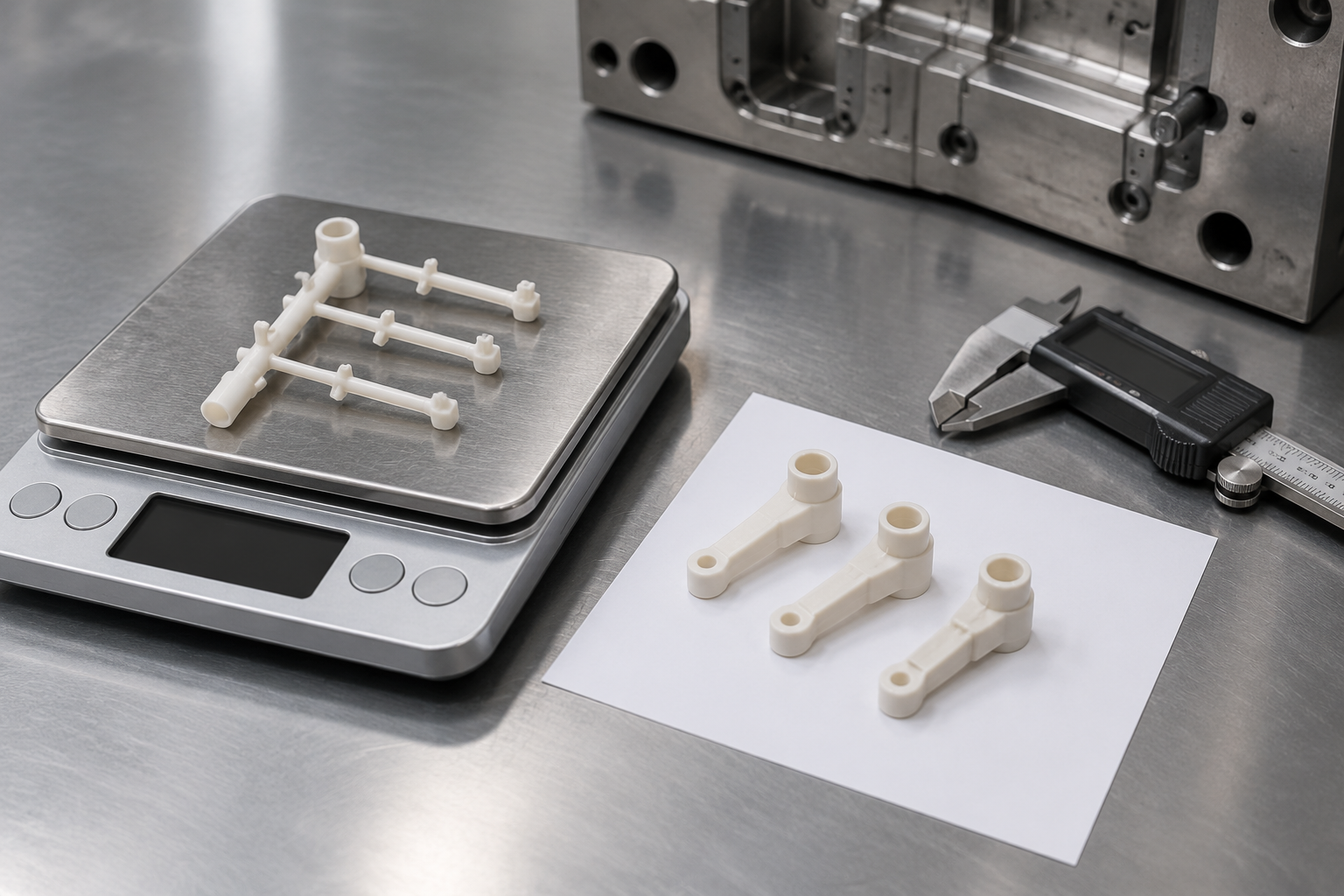
Runner weight is recorded per shot from the trial, not estimated from the drawing. It is the input the whole cost comparison depends on.
| Recorded at trial | How it is used |
|---|---|
| Runner weight per shot | Converts into annual material cost, and is the figure a future project should be compared against |
| Cycle time, with the settings that produced it | Separates the runner change from everything else that affects cycle, so a later difference can be attributed |
| Process settings for each heated zone | The starting point for the next run, and the evidence that the design runs inside the resin's window |
| Dimensional report on trial samples | Confirms the part, not just the tool. Required before accepting either |
| Appearance and gate condition | Whether the freeze point sits somewhere the gate mark is acceptable |
| Corrections made between trials | What was changed and why, so the record explains the final design rather than only describing it |
The number of trial rounds is quoted per project and is not published as a fixed figure. It depends on how far the first shot is from an acceptable part, which is a function of the design review rather than of the runner type. What is fixed is that no mould is accepted on a verbal “runs well”: the record above is the acceptance evidence.
Maintenance, Spares and Serviceability
Short answer: a hybrid runner has fewer heated components than a full hot runner and more than a cold runner. That middle position is the honest selling point, and it should be priced and planned rather than described as maintenance-free.
| Component | Failure mode | What makes it serviceable |
|---|---|---|
| Heater elements | Open circuit, drifted output, localised overheating | Accessible from the top plate without stripping the cavity plate; elements identified on the drawing |
| Thermocouples | Drift and false readings, usually read as a runner problem | Replaceable individually, with the correct type and position recorded |
| Controllers and wiring | Zone faults, connector damage, incorrect zone mapping after a repair | A wiring schedule that matches the physical zone numbering, supplied with the tool |
| Insulation and thermal separation | Degradation over time, raising heat loss and destabilising the cold section | Replaceable without remachining, and inspectable at service |
| Gates and sub-runner sections | Wear, particularly with filled grades | Inserted or replaceable detail where the wear rate justifies it |
| Ejection of the frozen runner | Stub left behind, stopping the press | Positive ejection and a check in the maintenance routine |
Two commercial points belong here rather than in a support conversation. First, asking which spares are recommended and whether they are held as standard items is a fair question at quotation, and the answer should be a list rather than reassurance. Second, the maintenance interval depends on the resin and the shot count, so it is stated per project.
What Ships With the Mould
Short answer: the document set is agreed at quotation, because a mould without its drawings and its trial record cannot be maintained by anyone except the toolmaker who built it. The set below is what the handover is built from.
| Document | Why the buyer needs it |
|---|---|
| Mould assembly and plate drawings | Any future repair, modification or second tool starts from these |
| Component list, with heated elements, thermocouples and controllers identified | Spares can be ordered by specification rather than by photograph |
| Trial record with process settings | Reproduces the accepted running condition |
| Dimensional report on trial samples | The acceptance evidence for the part |
| Runner weight measured per shot | The baseline for any later cost or design comparison |
| Wiring and temperature-controller schedule | Prevents zone-mapping errors after a repair or a controller swap |
| Maintenance instructions for wearing parts | Makes the service interval and the replacement procedure explicit |
Items outside this set — for example a full 3D mould model, or a spare heated section supplied with the tool — are listed separately at quotation rather than assumed to be included. Stating which is which is more useful than a long list of everything that might conceivably be provided.
The Cost Logic, Without a Made-Up Percentage
Short answer: the comparison is one subtraction and one division. The extra tooling is divided by the annual saving the runner produces, and the answer is a payback period in years. Every term below is measurable on your project; none of them is a property of the category.
Two cautions that change the answer more often than the resin price does. Reducing runner weight is not the same as reducing part cost by the same proportion, because the runner is only part of the shot and only part of it is recoverable. And a cycle-time difference measured on a trial tool should not be extrapolated to a production tool without confirming that the rest of the cycle is unchanged.
The interactive break-even estimator, with the full three-way comparison and the sensitivity to volume, is on hot runner vs cold runner. Keeping the calculator there and the engineering here means neither page repeats the other.
Frequently Asked Questions
What is a semi-hot runner mold?
It is a hybrid in which part of the runner system is held at melt temperature and part of it is not. In the configuration this service is built around, the main runner and sprue are heated so the material in them stays molten between shots, while the sub-runners that feed each cavity are unheated and solidify with the part, so they eject with the shot as a small runner stub. Because the term is not standardised, always confirm the heated and unheated sections on a section drawing rather than relying on the name.
How does a semi-hot runner differ from a full hot runner?
A full hot runner keeps the entire flow path from sprue to gate molten, so normally no runner solidifies and there is nothing to remove. A semi-hot system deliberately leaves the last stage unheated. That removes the heated nozzles, their controllers and their wiring from each drop, which lowers the tooling cost and the number of heated zones to maintain, at the cost of producing a small amount of solidified runner that is ejected each cycle.
Is a semi-hot runner cheaper than a full hot runner?
The initial tooling investment is usually lower than a full hot runner, because there are fewer heated components. Whether the total cost is lower depends on how much solidified runner the design produces, the resin price, the shot count over the tool's life, and the labour and machine time to remove and handle that runner. This page does not publish a percentage, because the figure is a result of a specific design and volume, not a property of the category.
Which materials can be used with a semi-hot runner?
Materials commonly evaluated include polyolefins, styrenics, ABS, polycarbonate and nylons, but suitability is decided per grade rather than per family. The limiting factors are the resin's thermal stability at the heated-section temperature, how long it can sit there without degrading, whether fillers abrade the heated components, and how the material behaves on colour changes. Glass or mineral filled grades need the wear question answered before the runner design is fixed.
What information is needed to quote a semi-hot runner mold?
A 3D model, a fully dimensioned 2D drawing with the critical tolerances and the cosmetic requirement, the resin grade and colour, the annual and lifetime quantity, the intended injection machine including shot capacity and tie-bar spacing, the gate type and permitted gate position, the target cycle and mould life, and for a conversion project the existing mould drawings. Without the machine data the runner and cavity layout cannot be checked against shot size and clamp force.
How is the runner decision evaluated?
By comparing the extra tooling investment against the recurring cost it removes. That means establishing the runner weight per shot for each candidate layout, multiplying by shots per year and resin price, allowing for how much of the solidified runner can be reground and at what ratio, and then adding any difference in cycle time, handling labour and maintenance. The comparison only means something when the shot count over the tool's life is known.
How long does mold manufacturing take?
It is quoted per project rather than published as a blanket figure, because it depends on design freeze, cavity count, mould size, whether standard components are in stock, and how many trial rounds the part needs. The schedule is broken into design approval, machining and assembly, trial and correction, and final acceptance, so each stage can be tracked separately. A date is given once the design is frozen and the component lead times are known.
What documents are supplied with the mold?
The document set is agreed at quotation. It can include the mould assembly and plate drawings, the component list with the heated elements, thermocouples and controllers identified, the trial record with the process settings used, dimensional reports on the trial samples, the runner weight measured per shot, the wiring and temperature-controller schedule, and maintenance instructions for the wearing parts. Items outside the standard set are listed rather than assumed.
Related Pages
| Page | What it covers |
|---|---|
| Hot runner vs cold runner | Three-way system comparison, when each makes financial sense, break-even calculation and an interactive estimator |
| Injection molding services | The moulding route: machines, materials, secondary operations and production capability |
| Injection mold making | Mould design, machining, assembly and tooling capability |
| Engineering materials | Resin families with property data, for the grade discussion |
| Custom plastic components | Component capability and finishing options for moulded parts |
| CNC machining services | Machining capability used for mould plates, inserts and details |
| Quality certifications | Quality system and certification status |
| Quotation | Commercial terms, payment and shipping |
Send the Part, the Press and the Shot Count
The runner decision is arithmetic, and it needs four numbers before it can be done: runner weight per shot in the candidate layout, shots over the tool's life, the resin price with your regrind policy, and the intended press. Send the model, the drawing, the grade, the quantity and the machine, and the review will come back with the architecture we would use, the runner weight we expect, and the points where the specification is still open.
What this page does and does not claim
This page publishes no percentage reduction in runner waste, no percentage difference in tool cost against a full hot runner, no tonnage figure and no blanket lead time. Those quantities depend on the part, the cavity layout, the resin and the shot count, and a page that states them is stating a result it has not measured. Where a number is needed, it is measured at trial and recorded.
It also does not restate the three-way cost comparison or the break-even estimator already published on our hot runner vs cold runner guide. That page is linked instead, so the service page and the selection guide keep separate jobs and do not compete for the same query with the same content.
The section drawing on this page is a schematic illustrating where the heated and unheated sections sit. It is not a production drawing, and the configuration for a specific project is confirmed on that project's tool drawings before manufacture.